1
CLEMENTS
Medium Vacuum Low Flow
Baby Mucus Regulator
SUC 89160
SUC 89162
User Manual
Manual No. SUC 91005 430
Issue 9
CLEMENTS
Safety
Thank you for purchasing this Clements
Vacuum Low Flow Baby Mucus Regulator.
Medium
For your safety it is imperative that this unit only be
operated by authorised personnel in accordance with the
instructions as described in this manual. Operated in
this way, the Medium Vacuum Low Flow Baby Mucus
Regulator will provide years of service.
Due to continual improvements in product design, the
Medium Vacuum Low Flow Baby Mucus Regulator. may
vary in detail from the descriptions in this manual. In the
event of further questions please contact your local
distributor or BMDi TUTA Healthcare direct.
User Manual
Medium Vacuum Low Flow Baby Mucus Regulator
Manual Number SUC 91005 430 Issue 9
Copyright © 2010 BMDi TUTA Healthcare Pty Ltd
The information in this manual was originated by, and is the exclusive
property of BMDi TUTA Healthcare Pty Ltd. It is furnished for customer
information only, and is not an authorisation or licence to make this
product or to furnish this information to others.
BMDi TUTA Healthcare Pty Ltd
Level 17, 275 Alfred St
North Sydney NSW 2060
Australia
Phone:
+61 2 9466 5300
Fax:
+61 2 9922 7165
Website: www.medaust.com
EC REP
2
Priory Analysts Ltd
The Pinnacle, 160 Midsummer Boulevard,
Milton Keynes, MK9 1FF, United Kingdom
C0123
CLEMENTS
Contents
Specifications ................................................ 4
Transportation and Storage .......................... 5
Installation .................................................... 6
Operation....................................................... 7
Safety Test .................................................... 8
Maintenance .................................................. 9
Cleaning and Sterilisation .......................... 10
Spare Parts .................................................. 10
Disassembly and Reassembly ..................... 12
Parts Assembly ............................................ 15
Troubleshooting .......................................... 17
Warranty ...................................................... 18
Contents
3
CLEMENTS
Intended Use
To vary the vacuum level of a continuous vacuum source,
within the stated operating vacuum range, for the aspiration of
fluids and particulate matter in medical procedures carried out
by clinically trained and authorised personnel.
Specifications
Vacuum Range
0 to –33 kPa, 0 to –250 mmHg
Maximum Flow
7 to 8 litres/minute
Flow Rate
0 to 8 litres of Free Air Per Minute (LFAPM)
Regulator
Mechanism
Suspended frictionless double diaphragm
Filter
Porous bronze filter, 90 micron
Safety
Pressure safety valve, ball and seat type
Gauge
Diaphragm Type
Dual scale, graduated in kPa and mmHg
Gauge Range
0 to – 60 kPa, graduated at 5 kPa
0 to – 450 mmHg graduated at 10 mmHg
Duty Cycle
Continuous operation
Dimensions
278H x 65W x 132D
Weight
1.0kg
Ambient Temperature
+5°C to 35°C
Standard Conditions
25°C, Sea Level, 101kPa
GMDN Code
37780
ARTG Number
174684
Class
Class I (EU Class IIa)
4
Specifications
CLEMENTS
Transportation and Storage
Environmental conditions for transportation and storage are
shown in the following table.
Parameter
Minimum
Maximum
Temperature
10ºC
40ºC
Humidity
60% RH
95% RH
Barometric Pressure
700 mBar
1060 mBar
Warning Symbols Legend
The warning symbols marked on the equipment and their
meanings are shown as follows.
Caution, consult accompanying documents
Waste Materials
The contents of the collection jars, suction tubing, bacteria
filter, internal exhaust filter may contain biohazard wastes.
Handle using safe handling procedures, which may include the
use of rubber gloves and eye protection, and dispose of
according to local protocols for biohazard materials.
Recycling
At the end of their service life, the Controller should be
dismantled if necessary, and returned to a local materials
recycling centre.
Transportation and Storage
5
CLEMENTS
Installation
Carefully examine the suction regulator for any visual signs of
damage that might have occurred during shipment.
Screw the suction regulator to the wall outlet with the index
handwheel or slot “V” at back of body into mounting wall
bracket. Turn on full vacuum by rotating the control knob fully
clockwise.
Occlude the inlet port at the bottom of the safety jar and check
the reading on the gauge. The reading should be equal to the
pipeline vacuum.
Occlude the regulator exhaust and check that the safety valve
is operating.
The valve should operate at 250 mm Hg (-33 kPa).
If the above reading is not obtained, the safety valve is not
working correctly.
To rectify the problem carry out the following.
1
Disconnect regulator from vacuum supply.
2
Remove the safety jar and unscrew the safety valve
assembly. Do not block the Safety Valve hole as this will
cause damage to the gauge if vacuum not disconnected.
2
Thoroughly clean all components.
3
Connect to a vacuum supply and turn the control knob to
the fully on position.
4
Reassemble the safety valve components, apply a small
amount of ‘Loctite’ to the thread and screw the assembly
into the jar cap approximately three turns.
5
Fit the safety jar, occlude the suction inlet and check
gauge reading.
If any further adjustment is required, remove the safety jar and
screw the safety valve in or out to obtain the correct reading.
Note. Do not block Safety Valve as this will cause damage to
the Gauge which will not be covered by the warranty.
6
Installation
CLEMENTS
Operation
To set the regulator to desired setting
1 Occlude inlet
2 Wind regulator control knob to register higher than required
setting
3 Allow setting to stabilise
4 Slowly wind back regulator knob to required level
Operation
7
CLEMENTS
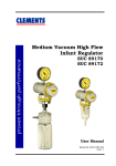
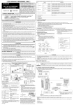
Safety Test for Vacuum Regulator with Variable
Setting
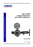
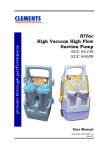
1.
Install the regulator to be tested as shown in the diagram.
2.
Set the vacuum source to -79 kPa and the regulator to
-1.6 kPa (-16 cmH2O).
3.
Reduce the vacuum source to -53 kPa and read the new
occluded vacuum on the regulator gauge.
4.
Set the regulator to -6.4 kPa (-64 cmH2O) and adjust the
vacuum source from -53 kPa to -79 kPa.
5.
Read the new occluded vacuum on the regulator gauge.
6.
Adjust the vacuum source from -79 kPa to -53 kPa and
read the new occluded vacuum on the regulator gauge.
7.
Repeat the above three times.
Each time the source vacuum is changed the regulator gauge
should read within 0.4 kPa of its’ setting before the change.
Arrangement For Testing Vacuum Regulator Setting
Regulator Gauge
Fitted to Regulator or
Line
Variable Vacuum Source
-53 to -92 kPa 50 l/min
On/Off Valve
Regulator
Under Test
8
Safety Test
CLEMENTS
Maintenance
Year
1st
Quarter
2nd
Quarter
3rd
Quarter
4th
Quarter
1
Check flow,
vacuum,
bronze filter
and safety
Check flow,
vacuum,
bronze filter
and safety
Check flow,
vacuum,
bronze filter
and safety
Check flow and
vacuum, bronze
filter and safety
valve
2
Check flow,
vacuum,
bronze filter
and safety
valve
Check flow,
vacuum,
bronze filter
and safety
valve
Check flow,
vacuum,
bronze filter
and safety
valve
Check flow and
vacuum. Strip and
inspect safety
valve parts and
replace ‘O’ ring
and filter.
3
Check flow,
vacuum,
bronze filter
and safety
valve
Check flow,
vacuum,
bronze filter
and safety
valve
Check flow,
vacuum,
bronze filter
and safety
valve
Check flow, and
vacuum and safety
valve. Check filter
and seals, replace
if necessary.
4
Check flow,
vacuum,
bronze filter
and safety
valve
Check flow,
vacuum,
bronze filter
and safety
valve
Check flow,
vacuum,
bronze filter
and safety
valve
Check flow and
vacuum. Strip and
inspect safety
valve parts and
replace ‘O’ ring
and filter.
5
Check flow,
vacuum,
bronze filter
and safety
valve
Check flow,
vacuum,
bronze filter
and safety
valve
Check flow,
vacuum,
bronze filter
and safety
valve
Check flow and
vacuum and safety
valve. Check filter
and seals, replace
if necessary.
Maintenance
9
CLEMENTS
Cleaning and Sterilisation : Regulator
Warning
Do not immerse or autoclave the Regulator unless the gauge,
diaphragm assembly and nylon balls have been removed.
Cleaning
Clean using a pH neutral disinfectant for wiping or immersion
cleaning. Flush after immersing using distilled water and dry
thoroughly before reassembly of the Regulator.
Sterilisation
The Regulator may be safely autoclaved at 121°C for 15
minutes, once the gauge, diaphragm assembly and nylon balls
have been removed.
Cleaning and Sterilisation : Jar
Cleaning
Clean using a pH neutral disinfectant for wiping or immersion
cleaning. Flush after immersing using distilled water and dry
thoroughly before reassembly of the Jar.
Sterilisation
The MAK collection jar and components are all autoclavable.
The jar and components may be safely autoclaved at 121°C for 15
minutes.
10
Cleaning and Sterilisation
CLEMENTS
Spare Parts
SUC 80297 001
KIT Yellow medical suction tubing (20 metre roll)
SUC 81500 043
Vacuum Controller spring
SUC 89101
KIT connector BS MK IV
SUC 89102
KIT Connector Puritan Bennett
SUC 89104
KIT connector Drager
SUC 89140 029
Knob Tension Spring
SUC 89140 036
KIT Overhaul for Regulators (O-Ring x4, Large
Diaphragm, Small Diaphragm, Valve Seat)
SUC 89140 085
MAK 300 antibacterial canister and lid
SUC 89140 087
Adapter for attaching canister to regulators
SUC 89150 011
Regulator Assembly Handle
SUC 89150 012
Regulator Assembly Tube
SUC 89160 004
Vacuum Gauge for Medium Vacuum Products
SUC 89240 088
MAK 300 jar only
SUC 89240 084
MAK 500 jar only
SUC 89240 090
HEPA bacterial filters for MAK 300
SUC 89310 001
Porous Bronze Filter (Pack of 20)
SUC 89455 001
KIT Plastic V bracket to hold suction devices
(Pack of 5)
SUC 89240 081
MAK 500 canister with lid
SUC 89210
Safety Jar for Regulator
SUC 89250 024
KIT Safety Valve
SUC 91005 430
User Manual for Medium Vacuum Baby Mucus
Regulator SUC 89160 / SUC 89162
Spare Parts
11
CLEMENTS
Disassembly and Reassembly
The Clements Suction Regulator is a precision machined and
assembled device that will, under normal operation, provide
many years of service.
In the event of any malfunction that requires the unit to be
dismantled the procedures described below should be followed.
Tools Required
Adjustable Wrench
Allen Keys
Circlip Pliers (internal)
Small Screwdriver
Drill Press (or G Clamp)
Special Tools (Clements SUC 89150 011 and SUC 89150 012)
Dismantling
1. Remove vacuum gauge.
2. Remove safety jar and bronze filter.
3. Remove safety jar cap by unscrewing the securing screw.
Take care that the small ‘O’ ring seal is not lost.
4. Remove the control knob by loosening the two grub screws.
5. Remove the compression spring and the nylon and fibre
washers.
6. Remove the stop screw from the main body.
7. Remove the circlip that retains the diaphragm assembly
and the belleville washer.
8. Remove the diaphragm assembly.
9. Unscrew the diaphragm compressor (left hand thread).
10.Remove the circlip from the spring barrel and take out the
control screw, and spring.
11.Remove the adjusting set screw, washer and spring from
inside the control screw.
12.Remove the diaphragm and piston assembly.
13.Remove the countersunk head screw and disassemble the
diaphragm and piston assembly.
12
Disassembly
CLEMENTS
Tool SUC 89150 011
Tool SUC 89150 012
Reassembly
1. Reassemble the diaphragm and piston assembly and
replace the countersunk head screw.
2. Lightly grease the fibre washer and reassemble the
adjusting set screw, washer and spring into the control
screw.
3. Insert the control screw, and spring into the spring barrel
and secure with the medium sized circlip.
4. Replace the diaphragm compressor (left hand thread) so
that it rests lightly against the diaphragm assembly.
5. Replace the belleville washer.
6. Compress the belleville washer and replace the large
circlip. (Clements special tools SUC 89150 011 and SUC
89150 012 will be needed for this operation).
7. Refit the stop screw into the main body.
8. Refit the vacuum gauge using a suitable thread sealant.
9. Place the nylon and fibre washers and knob spring into
position.
10.Lightly grease the ‘O’ ring and refit the jar cap to the main
body with the securing screw.
11.Place the bronze filter in its position with a twisting
action.
Reassembly
13
CLEMENTS
12.
13.
14.
15.
16.
17.
18.
19.
20.
14
Insert the safety jar into the jar cap.
Connect the regulator to a vacuum supply.
Occlude the inlet hole at the bottom of the main body
and slowly adjust the control screw until the vacuum
gauge just lifts off the zero position. This must be done
in conjunction with setting the Safety Valve. The
adjusting control screw must be wound up in 0.2 kPa
steps as should also the Safety Valve until the reading of
–33 kPa is reached. When first occluding the inlet take
care that the gauge does not over run the end of its
scale.
Carefully push the control knob onto the control screw
and lock it into position with the socket head screw.
Ensure that the stop pin is hard against the right hand
side of the stop screw.
Ensure that the vacuum gauge still lifts slightly off the
zero position with the knob in the off position and the
inlet occluded.
Remove the control knob label
Using a small screwdriver through the hole in the control
knob and with the control knob in the off position, turn
the adjusting set screw until the vacuum gauge reads
zero. This should be done whilst regulator is connected
to a 0 –12 lpm flowmeter to assist in checking for
vacuum leakage.
Ensure that the grub screws in the knob are tight and
replace the label.
Test the regulator as described in the Installation and
Operation section
Reassembly
CLEMENTS
1
4
9
2
3
11
14
13
8
5
12
10
6
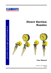
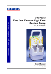
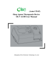
WARNING
This screw is factory set.
Do NOT adjust. Adjusting
it will affect vacuum
calibration.
This is a Safety Valve. Do
NOT block off while unit
is turned on
7
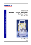
SUC 89162
Item Description
Item
Description
1
Gauge
8
Piston Assembly
2
Valve
9
Control Knob
3
Outer Spacer
10
Large Diaphragm
4
Control Spring
11
Small Diaphragm
5
Diaphragm Compressor
12
Jar Cap
6
Bronze Filter
13
Adjusting Screw
7
Safety Jar
14
Control Screw
Parts Assembly
15
CLEMENTS
1
4
9
2
3
11
14
13
8
5
12
10
6
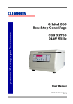
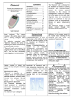
WARNING
This screw is factory set.
Do NOT adjust. Adjusting
it will affect vacuum
calibration.
This is a Safety Valve. Do
NOT block off while unit
is turned on
7
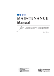
SUC 89160
Item Description
16
Item
Description
1
Gauge
8
Piston Assembly
2
Valve
9
Control Knob
3
Outer Spacer
10
Large Diaphragm
4
Control Spring
11
Small Diaphragm
5
Diaphragm Compressor
12
Jar Cap
6
Bronze Filter
13
Adjusting Screw
7
Safety Jar
14
Control Screw
Parts Assembly
CLEMENTS
Troubleshooting
Fault
Check
Rectify
No reading on
suction gauge
Pipeline supply
Safety Jar fitting
‘O’ Ring Seal
Connection to wall
Blockage in regulator
Supply source
Tighten into body
Replace if damaged
Check for leaks
Dismantle and clean
Full scale reading on
suction gauge at all
settings
Debris on valve seat
Dismantle and clean
Suction gauge
reading creeps
upwards
Debris on valve seat
Dismantle and clean
Suction gauge
reading creeps
downwards
Pipeline supply
Safety Jar fitting
‘O’ Ring Seal
Regulator
Diaphragms
Supply source
Tighten into body
Replace if damaged
Dismantle and check
replace if damaged
Slow response to
suction setting
Bronze Filter
Metering Jet
Clean or replace
Replace if worn
Troubleshooting
17
CLEMENTS
Warranty
BMDi TUTA Healthcare Pty Limited ("BMDi TUTA Healthcare") warrants
that this product is free from defects in workmanship and materials for
a period of 12 months from the date of shipment by BMDi TUTA
Healthcare or its authorised agent to the purchaser. Subject to the
conditions of this warranty, if the product fails to operate for any
reason within the warranty period and the product is returned to the
place of purchase at the purchaser's expense, BMDi TUTA Healthcare
will repair or replace the product free of charge.
If a valid warranty claim is made within 30 days from the date of
shipment, then BMDi TUTA Healthcare will also reimburse the
purchaser for reasonable freight costs in returning the product to the
place of purchase.
Conditions of Warranty
1.
The product must be returned to the place of purchase with proof
of purchase.
2.
This warranty is only available to the original purchaser of the
product.
3.
The product must not have had its serial number removed,
defaced or changed, its casing opened, its power supply altered or
have been tampered with in any other way.
4.
This warranty does not cover :
inadequate or incorrect site preparation;
improper installation;
connection to the wrong voltage;
failure of the product due to misuse;
the use or operation of the product outside of the physical,
electrical or environmental specifications of the product;
use in a manner or environment in which the product is not
designed to be used;
improper adjustment, calibration or operation by the purchaser;
the use of accessories including consumables, hardware or
software which were not manufactured or approved in writing by
BMDi TUTA Healthcare;
18
Warranty
CLEMENTS
any modifications of the product which were not authorised in
writing by BMDi TUTA Healthcare;
any contamination or leakages caused or induced by the
purchaser; and
inadequate or improper maintenance of the product.
5.
This warranty does not cover normal wear and tear.
6.
BMDi TUTA Healthcare will not be responsible for damage or loss
caused during shipping.
7.
In Australia, apart from any warranties implied by the Trade
Practices Act 1974 all other warranties expressed or implied and
whether arising by virtue of statute or otherwise are hereby
excluded.
8.
Outside Australia, all other warranties expressed or implied and
whether arising by virtue of statute or otherwise (including any
warranties implied by the Vienna Convention) are hereby
excluded.
9.
BMDi TUTA Healthcare' obligations under this warranty are
limited to the repair or replacement of the product, within the
terms of this warranty and the total liability of BMDi TUTA
Healthcare for loss or damage of every kind whether arising
pursuant to the terms of the sale of the product or otherwise in
connection with the product is limited to the amount paid by the
purchaser to BMDi TUTA Healthcare for the product.
10. Apart from any liability imposed by Part VA of the Trade Practices
Act, BMDi TUTA Healthcare accepts no other liability for any loss
or damage occasioned (including consequential loss or damages)
in any way as a result of the use of the product.
11. The warranty does not extend to cover damage to the following
parts as they are inherently prone to wear :
motor brushes
12. This warranty does not extend to cover corrosion due to any cause
nor to any damage to painted or anodised surfaces.
13. BMDi TUTA Healthcare will give the purchaser the benefit of any
manufacturer's warranty in respect of any components in the
product which were not manufactured by BMDi TUTA Healthcare,
if such a manufacturer's warranty is available.
Warranty
19