Download Orbital 360 User Manual
Transcript
CLEMENTS
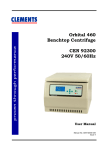
Orbital 360
Benchtop Centrifuge
CEN 91700
240V 50Hz
User Manual
Manual No. CEN 91700 017
Issue 7
CLEMENTS
Safety
Thank you for purchasing this Clements Orbital 360
Centrifuge For your safety it is imperative that this unit
only be operated by authorised personnel in accordance
with the instructions as described in this manual. Operated
in this way, the Orbital 360 Centrifuge will provide the
standard of service specified.
Due to continual improvements in product design, the
Orbital 360 Centrifuge
may vary in detail from the
descriptions in this manual. In the event of further
questions please contact your local distributor or BMDi
TUTA Healthcare direct.
User Manual Orbital 360 Centrifuge
Manual Number CEN 91700 017 Issue 7
Copyright © 2010 BMDi TUTA Healthcare Pty Ltd
The information in this manual was originated by, and is the exclusive
property of BMDi TUTA Healthcare Pty Ltd. It is furnished for customer
information only, and is not an authorisation or licence to make this
product or to furnish this information to others.
BMDi TUTA Healthcare Pty Ltd
Level 17, 275 Alfred St
North Sydney NSW 2060
Australia
Phone:
+61 2 9466 5300
Fax:
+61 2 9922 7165
Website: www.medaust.com
2
CLEMENTS
Contents
Description and Features ........................................ 4
Specifications .......................................................... 5
Warnings and Cautions ........................................... 6
Installation .............................................................. 7
Controls ................................................................... 8
Operation ............................................................... 10
Parameter Setting Menu ....................................... 12
Operation Summary .............................................. 14
Rotors .................................................................... 15
Accessories and Spares ......................................... 17
Cleaning and Maintenance ................................... 18
Fuse Replacement and Error Codes ..................... 19
Troubleshooting .................................................... 20
RCF Graphs............................................................ 21
Warranty ................................................................ 22
Contents
3
CLEMENTS
Description
The Orbital 360 Centrifuge is a versatile, compact and reliable
benchtop centrifuge. It is designed for clinical and small
laboratory applications where precise digital control of speed and
time is required.
Features
4
•
Brushless
operation
DC
motor
•
Accurate digital control of speed and time for repeatable
processing
•
High visibility LED display with touch control panel
•
Electronic lid interlock to ensure that centrifuge can be
started and run only with lid locked
•
Stainless steel bowl
•
Adjustable
samples
•
Selectable rpm or RCF display
•
Previous parameters maintained through power off/on
acceleration
technology
and
for
low
deceleration
Description and Features
maintenance
for
sensitive
CLEMENTS
Specifications
Speed Range
100 to 5000 rpm
Maximum RCF
4100 x g
Speed Accuracy
±50 rpm
Time Range
1 to 99 minutes
Angle Rotors
24 x 10 ml
Swing-out Rotors
4 x 50 ml
12 x 15 ml
24 x 5 ml
Power Requirement
220-240V 50/60Hz 5A
Electrical Protection
Class I
Noise
< 65dB(A)
Dimensions
370 (W) x 250 (H) x 432 (D) mm
Weight
15kg
Environment
Indoor
10 to 35°C, RH < 85%
Package Contents
Item
Description
Qty
CEN 91700
Cell Cycle 360 Centrifuge 240V 50Hz
1
CEN 91700 036
Tool, Rotor Screwdriver, Philips Head,
110 x 5.5mm
Tool, Lid Release Screwdriver, Philips
Head, 120 x 2.9mm
Lead, Mains Power, IEC Socket –
Earthed Australian Plug
Kit, Fuse, 5 x 20mm, T5.0A 250V
(Pack 4)
1
CEN 91700 037
CEN 91700 038
CEN 91700 040
Specifications
1
1
1
5
CLEMENTS
Warnings and Cautions
For safe operation ensure that users read, understand and
observe the instructions and recommendations in this user
manual.
Power
Ensure that the mains power supply matches that shown on the
rating label of the centrifuge.
Flammable Samples
The centrifuge is not flameproof. Do not use flammable samples in
the centrifuge. Do not store flammable or volatile material within
300mm of the centrifuge.
Biohazardous Samples
Local protocols must be observed when handling potentially
biohazardous materials. Carriers with aerosol protection are to be
used.
Fluid Spill
Do not allow fluids to enter the centrifuge. If a spill occurs wipe
clean, paying attention to the nature of the material.
Balancing
The centrifuge must always be run with a full complement of
buckets or carriers. Balance samples either by eye or by weighing.
Fill unused tubes with an equivalent amount of fluid as in sample
tube.
Operating
Do
Do
Do
Do
6
not
not
not
not
stand within 300mm of centrifuge while it is running.
move centrifuge while the rotor is spinning.
open lid while rotor is spinning.
attempt to stop rotor by hand.
Warnings and Cautions
CLEMENTS
Installation
Unpacking
Keep centrifuge horizontal while removing it from carton. Retain
packaging for transporting centrifuge. With power off, release lid
lock by inserting manual release tool in small hole on top right
hand side of centrifuge. Keep tool parallel to front of panel and
press release plate. Remove tool.
Remove packing, carriers etc from centrifuge bowl. Ensure that
bowl is clean.
Location
The centrifuge should be placed on a solid level surface in a well
ventilated area. The back of the centrifuge must be at least 10cm
away from any wall or vertical surface.
Power Requirements
Before connecting the centrifuge to the mains power supply,
ensure that the electricity supply conforms to the requirements for
voltage and frequency shown on the rating label on the back of the
unit.
The power supply should be stable, clean and free of surges and
brownouts.
Connect the centrifuge to the mains power supply using the
supplied earthed power cable.
For extended periods of non-use, switch off main power switch on
rear panel of centrifuge.
Installation
7
CLEMENTS
Controls
Rear View
Front View
Manual
Lid release
access hole
Control panel
On/Off Switch
8
IEC power inlet
Fuse holder
Condition
LED Display Shows
In Spin Cycle
Actual Values of Speed / RCF and Time Remaining
Rotor Stopped
Set Values of Speed / RCF and Time
Setting Mode
Set Values of Parameter
Error
Error code n of form En
Controls
CLEMENTS
Controls
Item
Function
On/Off Switch
Switches mains power to centrifuge.
IEC Inlet
Mains power inlet. Also contains fuse holder.
Lid release access hole
Access for manual lid release tool. Centrifuge
must be disconnected from power.
LED Speed Display
Shows actual and set speed in either rpm or
RCF.
LED Time Display
Shows set time and time remaining in minutes.
Shows error code n of form En.
RCF Indicator
Decimal point of right-most digit of speed
display indicates RCF when lit and spinning.
STOP / OPEN Button
Stops spin cycle. When rotor has stopped acts
as lid release button. Cancels error condition.
START Button
Starts spin cycle.
PULSE Button
Spins rotor when held down.
ENTER Button
Enters and saves changed parameters. Exits
parameter setting mode.
INC Button
Increases value of set parameters.
DEC Button
Decreases value of set parameters.
RCF / RPM Button
Switches between display of RCF and rpm.
Times out after 10 seconds.
MENU Button
Steps through parameter change menu in
circular fashion.
SPIN LED (Green)
Indicates that spin cycle is in progress.
STOP LED (Red)
Indicates that spin cycle is stopping.
Controls
9
CLEMENTS
Operation
Rotor Fitting
1. Open lid and switch off centrifuge.
2. Remove carriers from rotor.
3. While supporting rotor with one hand, unscrew (CCW) rotorretaining cap screw.
4. Lift off rotor being careful not to bend or apply side load to
motor shaft.
5. Select a compatible rotor, align the slot in the rotor shaft
with the drive pin in the motor shaft and fit together.
6. Fit cap screw and washer to rotor.
7. While supporting rotor with one hand, hand tighten (CW)
rotor-retaining cap screw - again being careful not to bend
or apply side load to motor shaft..
8. Confirm that rotor rotates smoothly and evenly by hand.
Carrier Fitting (swing-out style rotors)
1. Fit a full complement of compatible carriers to the rotor.
2. Ensure that carriers are fully seated and can swing freely.
3. Switch centrifuge power on.
Tube Fitting
Select a full complement of compatible tubes with an RCF
rating in excess of the maximum RCF of the centrifuge.
Balancing of Samples
It is important that the samples are correctly balanced within the
centrifuge prior to starting the unit. For correct balance there are
two requirements:
1.
2.
10
Balance the weight of the samples
Balance the location of the samples
Operation
CLEMENTS
1.
Balance the weight of the samples
For every sample in the centrifuge there must be a balancing
sample of equal weight. The samples may be balanced 'by eye' i.e.
two samples appear to contain the same volume and are therefore
approximately the same weight.
Where delicate samples are involved, it is recommended that the
samples be placed in Tube Carriers and balanced by weighing
them. This will ensure that vibration during the centrifugation
process will be kept to a minimum.
2.
Balance the location of the samples
The samples must be placed on the Rotor so that the weight of the
samples is equally distributed. To do this the equally weighted
samples must be placed in diametrically opposite positions on the
rotor.
Note:
Even though the Orbital 360 is designed to absorb
considerable out-of-balance forces, running the centrifuge with
out-of-balance samples will cause excessive vibration. This will
disturb the samples, affect the overall performance of the unit and
may lead to mechanical damage.
Cushion Fitting
To ensure that the cushions are correctly fitted it is recommended
that the cushion be fitted to the tube while it is inverted. The
carrier (or carrier plus hanger) is placed over the tube and cushion
– still inverted. The assembly is fitted to the rotor. Confirm that all
tubes are at the same height by observing the graduation marks
at the open end of the carrier
Note that this should be done every time that
a tube is placed in a carrier. A cushion that
was previously correctly placed in the carrier
can momentarily adhere to the tube as it is
withdrawn and then sit at an angle.
Operation
1
2
3
11
CLEMENTS
Parameter Setting Menu
Press MENU to select parameter setting mode.
Each press of the MENU button advances to the next parameter.
Press ENTER to save the parameters and exit the parameter setting
mode.
Parameter setting mode is automatically cancelled after a
5 second timeout with no button pressed.
Speed / RCF
[rpm] / [xg]
Time
[minutes]
Acceleration
Factor 1 - 9
Deceleration
Factor 1 - 9
Rotor Fitted
Rotor 1 - 4
Set Rotor Fitted
Note: It is essential that the rotor setting matches the rotor
fitted. Otherwise the rotor could be subject to speeds in
excess of its rating leading to damage to the rotor.
1. Ensure the rotor is stopped.
2. Press the MENU button until the display shows rot.
3. Press the INC or DEC buttons until the rotor number matches
the rotor that is fitted to the centrifuge.
4. Press the ENTER button to save the setting.
12
Parameter Setting Menu
CLEMENTS
Select RPM or RCF
The decimal point of the right-most digit of the speed display
indicates RCF when lit.
Press the RCF / RPM button to toggle between RCF and rpm
display modes.
The RCF / RPM mode can be changed at any time while
spinning. Display mode reverts to RPM after 10 seconds.
Set Speed
1. Press MENU button until 4-digit speed display flashes.
2. Press INC or DEC to select required speed. Note that speed
changes in steps of 100rpm and will auto-increment or auto
-decrement if the INC or DEC button is held down.
3. Press the ENTER button to save the setting.
Set Time
1. Press MENU button until 2-digit time display flashes.
2. Press INC or DEC to select required time. Note that time
changes in steps of 1 minute and will auto-increment or
auto-decrement if the INC or DEC button is held down.
3. Press the ENTER button to save the setting.
Set Acceleration Profile
1. Press the MENU button until the display shows ACC.
2. Press the INC or DEC buttons to select the required
acceleration profile. Acceleration profiles range from a
minimum of 1 to a maximum of 9.
The default acceleration profile is 5.
3. Press the ENTER button to save the setting.
Set Deceleration Profile
1. Press the MENU button until the display shows dEC.
2. Press the INC or DEC buttons to select the required
deceleration profile. Deceleration profiles range from a
minimum of 1 to a maximum of 9.
The default deceleration profile is 5.
3. Press the ENTER button to save the setting.
Parameter Setting Menu
13
CLEMENTS
Operation Summary
See previous sections for details of individual steps.
1. Confirm that correct rotor is selected.
2. Load a balanced and evenly distributed set of sample tubes.
3. Close lid.
4. Confirm acceleration and deceleration profiles.
5. Set required speed.
6. Set required spin time.
7. Press START button.
• The rotor will automatically accelerate to the set speed
using the set acceleration profile.
• The rotor will spin for the set time with the time display
counting down to zero.
• The rotor will automatically decelerate to zero using the
set deceleration profile.
• When the rotor has stopped the beeper will signal the
end of the spin cycle.
8. Press the STOP / OPEN button to unlock the lid.
Note: For repeat operations using the same settings, the only
steps required are to load the samples, close the lid
and press the START button.
The previous settings are automatically restored at
power-on.
Rotor Setting
Rotor
Type
Carriers
/ Tubes
Max
rpm
Max
xg
Rotor
Setting
CEN 91700 001 Angle
24 x 10ml
4000
2850
1
CEN 91700 002 Swing
12 x 15ml
5000
4100
2
CEN 91700 003 Swing
24 x 5ml
5000
4100
4
CEN 91700 004 Swing
4 x 50ml
4200
2760
3
14
Operation Summary
CLEMENTS
Angle Rotor CEN 91700 001
24 x 10ml Tubes
Max rpm: 4000
Max RCF: 2850
Rotor Setting: 1
Swing Rotor CEN 91700 002
12 x 15ml Carriers
Max Speed: 5000rpm
Max RCF: 4100
Rotor Setting: 2
Rotors
15
CLEMENTS
Swing Rotor CEN 91700 003
24 x 5ml Carriers
Max Speed: 5000rpm
Max RCF: 4100
Rotor Setting: 4
Swing Rotor CEN 91700 004
4 x 50ml Carriers
Max Speed: 4200rpm
Max RCF: 2760
Rotor Setting: 3
16
Rotors
CLEMENTS
Accessories and Spares
Accessories
CEN 91700 001
Angle Rotor for 24 x 10ml Tubes for Orbital 360
CEN 91700 002
Swing Rotor with 12 x 15ml Carriers for Orbital 360
CEN 91700 003
Swing Rotor with 24 x 5ml Carriers for Orbital 360
CEN 91700 004
Swing Rotor with 4 x 50ml Carriers for Orbital 360
CEN 91700 034
Kit, Adaptor 50 - 15ml / 8.5ml (Pack 4)
CEN 91700 035
Kit, Adaptor 50 - 6ml (Pack 4)
Spares
CEN 91700 005
Motor Drive PCB Assembly for Orbital 360
CEN 91700 008
LED Display PCB for Orbital 360
CEN 91700 009
DC Brushless Motor for Orbital 360 (240V)
CEN 91700 010
Hinge set for Orbital 360
CEN 91700 011
Electronic Lid Lock for Orbital 360 (240V)
CEN 91700 012
Power Transformer for Orbital 260/360 (240V)
CEN 91700 013
Carrier Set 12 x 15ml for Swing Rotor CEN 91700 002
for Orbital 360
CEN 91700 014
Carrier Set 24 x 5ml for Swing Rotor CEN 91700 003
for Orbital 360
CEN 91700 015
Carrier Set 4 x 50ml for Swing Rotor CEN 91700 004
for Orbital 360
CEN 91700 017
User Manual for Orbital 360
CEN 91700 040
Kit, Fuse, 5 x 20mm, T5.0A 250V (Pack 4)
CEN 91700 041
Seal, Bowl, Rim for 360 Centrifuge
CEN 91700 046
Kit, Rubber Motor Mount (Pack 3) inc Screws (6)
Accessories and Spares
17
CLEMENTS
Cleaning
Spills must be cleaned up immediately. The centrifuge should be
regularly cleaned to maintain its appearance and to ensure that
dust or other damaging materials do not build up and affect the
performance of the unit.
• Before cleaning the centrifuge disconnect it from the mains
power supply.
• Clean the exterior surfaces using a proprietary furniture
polish with a clean soft cloth .
• Wipe the bowl and rotor with a clean soft cloth dampened in a
solution of warm water and a mild detergent. (If moisture can
be wrung from the cloth, it is wet, not damp.)
• Most sterilising agents at their standard cleaning dilution can
be used on the bowl.
• Remove cleaning agent residue by wiping with a dry paper
towel.
• Solvent-based cleaning agents and abrasive cleaning agents
should never be used on the Orbital 360.
Maintenance
The Orbital 360 is designed to provide extended and reliable
operation. To ensure proper operation and maximise the life of the
centrifuge the following requirements must be observed:
• The centrifuge should be inspected by authorised service
personnel every six months as part of your routine
maintenance plan
• Confirm that lid interlock prevents starting when lid is
unlocked and also prevents opening lid before rotor has
stopped
• Using an optical tachometer confirm that the speed remains
within specification
• Use only genuine Clements spare parts
18
Cleaning and Maintenance
CLEMENTS
Fuse Replacement
1. Switch off mains power to centrifuge using switch on rear
panel.
2. Remove power cable from centrifuge IEC mains power inlet.
3. Slide out fuse holder and remove blown fuse from U-shaped
holder.
4. Replace fuse with one matching fuse rating on rating label.
(A spare fuse is normally fitted to the fuse holder.)
Error Conditions
Error Code Fault
Action
E4
Lid not closed when START
button pressed
Close lid.
Adjust Lid Closed limit
switch.
E6
Overspeed condition:
Incorrect rotor setting
Power control PCB fault
Motor fault
++ SWITCH OFF ++
Verify correct rotor setting
Replace power PCB
Replace motor
E7
Underspeed condition:
Mains power fault
Power control PCB fault
Tachometer circuit fault
++ SWITCH OFF ++
Check transformer
Replace power control PCB
Check tachometer circuit
E9
Communication fault:
Fault in cable between
display PCB and power
control PCB
++ SWITCH OFF ++
Check cable and connections
Note:
When error conditions E6, E7 or E9 occur,
the centrifuge must be SWITCHED OFF and
the fault corrected before proceeding.
Error Conditions
19
CLEMENTS
Troubleshooting
Symptom
Possible Cause
Action
LED display not lit
when power switched
on.
Power cable not
plugged in securely.
Plug in power cable.
No power supply.
Confirm power supply.
Fuse has blown.
Replace fuse.
Loose connecting
cables.
Check and re-seat
connectors.
Lid not closed.
Close lid.
Loose connecting
cables.
Check and re-seat
connectors.
Power transformer
fault.
Replace power
transformer.
Motor fault.
Replace motor.
PCB fault.
Replace PCB.
Imbalanced carriers or
sample tubes.
Rebalance.
Broken sample tube.
Clean and replace
sample tube.
Unequal weight
samples.
Make samples equal
weight.
Damaged platform
shock absorber.
Replace shock
absorber.
Rotor does not spin
when START button
pressed.
Excessive vibration.
20
Troubleshooting
CLEMENTS
RCF Graphs
160
140
120
50 ml
100
RCF
[g]
80
60
40
20
0
100
200
300
400
500
600
700
800
900 1000
rpm
4000
5 & 15 ml
3000
RCF
[g]
2000
50 ml
1000
0
0
1000
2000
3000
4000
5000
rpm
RCF Graphs
21
CLEMENTS
Warranty
BMDi TUTA Healthcare Pty Ltd warrants that this product is free from defects
in workmanship and materials for a period of 12 months from the date of shipment
by BMDi TUTA Healthcare or its authorised agent to the purchaser. Subject to the
conditions of this warranty, if the product fails to operate for any reason within the
warranty period and the product is returned to the place of purchase at the
purchaser's expense, BMDi TUTA Healthcare will repair or replace the product free
of charge.
If a valid warranty claim is made within 30 days from the date of shipment, then
BMDi TUTA Healthcare will also reimburse the purchaser for reasonable freight
costs in returning the product to the place of purchase.
Conditions of Warranty
1.
The product must be returned to the place of purchase with proof of
purchase.
2.
This warranty is only available to the original purchaser of the product.
3.
The product must not have had its serial number removed, defaced or
changed, its casing opened, its power supply altered or have been tampered
with in any other way.
4.
This warranty does not cover :
• inadequate or incorrect site preparation;
• improper installation;
• connection to the wrong voltage;
• failure of the product due to misuse;
• the use or operation of the product outside of the physical, electrical or
environmental specifications of the product;
• use in a manner or environment in which the product is not designed to be
used;
• improper adjustment, calibration or operation by the purchaser;
• the use of accessories including consumables, hardware or software which
were not manufactured or approved in writing by BMDi TUTA Healthcare ;
22
Warranty
CLEMENTS
• any modifications of the product which were not authorised in writing by
BMDi TUTA Healthcare ;
• any contamination or leakages caused or induced by the purchaser; and
• inadequate or improper maintenance of the product.
5.
This warranty does not cover normal wear and tear.
6.
BMDi TUTA Healthcare will not be responsible for damage or loss caused
during shipping.
7.
In Australia, apart from any warranties implied by the Trade Practices Act
1974 all other warranties expressed or implied and whether arising by virtue
of statute or otherwise are hereby excluded.
8.
Outside Australia, all other warranties expressed or implied and whether
arising by virtue of statute or otherwise (including any warranties implied by
the Vienna Convention) are hereby excluded.
9.
BMDi TUTA Healthcare’s obligations under this warranty are limited to the
repair or replacement of the product, within the terms of this warranty and
the total liability of BMDi TUTA Healthcare for loss or damage of every kind
whether arising pursuant to the terms of the sale of the product or otherwise
in connection with the product is limited to the amount paid by the
purchaser to BMDi TUTA Healthcare for the product.
10.
Apart from any liability imposed by Part VA of the Trade Practices Act, BMDi
TUTA Healthcare accepts no other liability for any loss or damage occasioned
(including consequential loss or damages) in any way as a result of the use of
the product.
11.
The warranty does not extend to cover damage to the following parts as they
are inherently prone to wear :
• motor brushes
12.
This warranty does not extend to cover corrosion due to any cause nor to any
damage to painted or anodised surfaces.
13.
BMDi TUTA Healthcare will give the purchaser the benefit of any
manufacturer's warranty in respect of any components in the product which
were not manufactured by BMDi TUTA Healthcare , if such a manufacturer's
warranty is available.
Warranty
23


