1
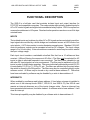
ACCES I/O PRODUCTS INC
10623 Roselle St, San Diego, CA 92121
Tel: (619)550-9559 FAX: (619) 550-7322
ISOLATED DIGITAL
INPUT / RELAY OUTPUT
CARD
MODEL IIRO-8
USER MANUAL
File: MIIRO-8.d1
ISOLATED DIGITAL INPUT/RELAY OUTPUT CARD
IIRO-8
USER
MANU
AL
NOTICES
The information in this document is provided for reference only. ACCES I/O PRODUCTS
INC does not assume any liability arising out of the application or use of the information
or products described herein. This document may contain or reference information and
products protected by copyrights or patents and does not convey any license under the
patent rights of ACCES, nor the rights of others.
IBM PC, PC/XT, and PC/AT are registered trademarks of the International Business
Machines Corporation.
Printed in USA. Copyright 1998 by ACCES I/O PRODUCTS INC, 10623 Roselle St., San
Diego,CA 92121. All rights reserved.
ISOLATED DIGITAL INPUT/RELAY OUTPUT CARD
IIRO-8
USER
MANU
AL
TABLE OF CONTENTS
INSTALLATION . . . . . . . . . . . . . . . . . . . . . . . . . . . . . . . . . . . . . . .
CD INSTALLATION . . . . . . . . . . . . . . . . . . . . . . . . . . . . . . . . .
3.5-INCH DISKETTE INSTALLATION . . . . . . . . . . . . . . . . . . . .
DIRECTORIES CREATED ON THE HARD DISK . . . . . . . . . . .
INSTALLING THE CARD . . . . . . . . . . . . . . . . . . . . . . . . . . . . .
1-1
1-1
1-1
1-2
1-4
FUNCTIONAL DESCRIPTION . . . . . . . . . . . . . . . . . . . . . . . . . . . .
INPUTS . . . . . . . . . . . . . . . . . . . . . . . . . . . . . . . . . . . . . . . . . .
INTERRUPTS . . . . . . . . . . . . . . . . . . . . . . . . . . . . . . . . . . . . . .
OUTPUTS . . . . . . . . . . . . . . . . . . . . . . . . . . . . . . . . . . . . . . . . .
BLOCK DIAGRAM . . . . . . . . . . . . . . . . . . . . . . . . . . . . . . . . . .
2-1
2-1
2-1
2-2
2-2
OPTION SELECTION . . . . . . . . . . . . . . . . . . . . . . . . . . . . . . . . . . .
FILTER RESPONSE SWITCH . . . . . . . . . . . . . . . . . . . . . . . . .
INTERRUPTS . . . . . . . . . . . . . . . . . . . . . . . . . . . . . . . . . . . . . .
OPTION SELECTION MAP . . . . . . . . . . . . . . . . . . . . . . . . . . .
3-1
3-1
3-1
3-2
ADDRESS SELECTION . . . . . . . . . . . . . . . . . . . . . . . . . . . . . . . . . 4-1
ADDRESS ASSIGNMENTS FOR 286/386/486 COMPUTERS . 4-1
PROGRAMMING . . . . . . . . . . . . . . . . . . . . . . . . . . . . . . . . . . . . . .
DIGITAL INPUTS . . . . . . . . . . . . . . . . . . . . . . . . . . . . . . . . . . .
RELAY OUTPUTS . . . . . . . . . . . . . . . . . . . . . . . . . . . . . . . . . .
PROGRAMMING EXAMPLES . . . . . . . . . . . . . . . . . . . . . . . . .
5-1
5-1
5-1
5-2
SOFTWARE . . . . . . . . . . . . . . . . . . . . . . . . . . . . . . . . . . . . . . . . . . 6-1
CONNECTOR PIN ASSIGNMENTS . . . . . . . . . . . . . . . . . . . . . . . . 7-1
SPECIFICATION . . . . . . . . . . . . . . . . . . . . . . . . . . . . . . . . . . . . . . . 8-1
WARRANTY . . . . . . . . . . . . . . . . . . . . . . . . . . . . . . . . . . . . . . . . . . 9-1
i
ISOLATED DIGITAL INPUT/RELAY OUTPUT CARD
IIRO-8
USER
MANU
AL
INSTALLING THE CARD
Before installing the card carefully read the ADDRESS SELECTION and OPTION
SELECTION Sections of this manual and configure the card according to your
requirements. Use the special software program called SETUP provided on CD with the
card. It supplies visual aids to configure all areas of the board.
Be especially careful with address selection. If the addresses of two installed functions
overlap, you will experience unpredictable computer behavior. If unsure what locations
are available, you can use the FINDBASE program provided to locate blocks of available
addresses.
To install the card:
1. Remove power from the computer.
2. Remove the computer cover.
3. Remove blank I/O backplate.
4. Install jumpers for selected options. See OPTION SELECTION.
5. Select the base address on the card. See ADDRESS SELECTION.
6. Install the card in an I/O expansion slot. Make sure that the card mounting bracket
is properly screwed into place and that there is a positive chassis ground.
7. Inspect for proper fit of the card and cables and tighten screws.
8. Replace the computer cover.
1-1
ISOLATED DIGITAL INPUT/RELAY OUTPUT CARD
IIRO-8
USER
MANU
AL
FUNCTIONAL DESCRIPTION
The IIRO-8 is a half-size card that provides isolated input and output interface for
PC/XT/AT and compatible computers. The card provides eight optically-isolated inputs for
AC or DC control signals and eight electromechanical relay outputs. IIRO-8 occupies four
consecutive addresses in I/O space. Read and write operations are done on an 8-bit-byte
oriented basis.
INPUTS
The isolated inputs can be driven by either AC or DC signals and are not polarity sensitive.
Input signals are rectified by a diode bridge and connected across an LED diode of an
opto-isolator. A 470-ohm resistor in series dissipates unused power. Standard 12/24 AC
control transformer outputs can be accepted as well as DC voltages. The input voltage
range is 5 to 24 volts (rms). External resistors connected in series may be used to extend
the input voltage range.
Each input circuit contains a switchable slow/fast filter that has a 10 millisecond time
constant. (Without filtering, the response is 20 uSec.) The filter must be selected for AC
inputs in order to eliminate response to zero crossings. The filter is also valuable for use
with slow DC input signals in a noisy environment. The filter may be switched out for DC
inputs in order to obtain faster response. Filters are individually selected by switch S2; IP0
is controlled by F0, IP1 by F1, IP2 by F2, etc. The filters are switched into the circuit when
the switch is moved to the ON position. The filters may also be controlled globally under
software control. All filters may be turned on by a read at base address +3. Filters that
have been activated by software may be disabled by a write to base address +3.
INTERRUPTS
When enabled by a software read to base address +2 (and when a jumper is installed to
select one of the interrupt levels IRQ2-7, IRQ10-12, and IRQ14-15), the IIRO-8 card
asserts an interrupt whenever any of the inputs changes state. Once an interrupt has
been generated and serviced, it must be cleared. A software write to base address +1 will
clear an interrupt.
This interrupt capability may be disabled by a software write to base address +2.
2-1
ISOLATED DIGITAL INPUT/RELAY OUTPUT CARD
IIRO-8
USER
MANU
AL
OUTPUTS
The electromechanical relay outputs are comprised of five FORM C SPDT outputs and
three FORM A SPST (normally open) type. The relays are all de-energized at power-on.
Data to the relays is latched by a write to the base address. On/off status of the relays can
be read back by a read at the base address.
BLOCK DIAGRAM
2-2
ISOLATED DIGITAL INPUT/RELAY OUTPUT CARD
IIRO-8
USER
MANU
AL
OPTION SELECTION
FILTER RESPONSE SWITCH
DIP switch S2 is used to select input filtering on a channel-by-channel basis. When S2-1
is ON, additional filtering is introduced for input bit 0, S2-2 for bit 1, etc.
Switch Section
Bit Filtered
IP0
IP1
IP2
IP3
IP4
IP5
IP6
IP7
S2-1
-2
-3
-4
-5
-6
-7
-8
This additional filtering provides a slower response as described previously and should
be used when AC inputs are applied. Note also, as previously described, that the filters
can be globally activated (or de-activated) under software control at base address +3.
INTERRUPTS
Select the desired interrupt level by installing a jumper at one of the locations marked
IRQxx. An interrupt is asserted by the IIRO-8 card when an input data bit changes state
if software enabled as previously described.
3-1
ISOLATED DIGITAL INPUT/RELAY OUTPUT CARD
IIRO-8
OPTION SELECTION MAP
3-2
USER
MANU
AL
ISOLATED DIGITAL INPUT/RELAY OUTPUT CARD
IIRO-8
USER
MANU
AL
ADDRESS SELECTION
IIRO-8 occupies four consecutive addresses in I/O space although only two addresses are
used. The base or starting address can be selected anywhere within the I/O address
range 100-3FF (except 1F0 through 1F8) for AT's and 200-3FF for XT's provided that it
does not cause an overlap with other functions. If the addresses of two installed functions
overlap, you will experience unpredictable computer behavior. The FINDBASE program
supplied by ACCES will assist you in selecting a base address that will avoid this conflict.
ADDRESS ASSIGNMENTS FOR 286/386/486 COMPUTERS
Hex Range
000-01F
020-03F
040-05F
060-06F
070-07F
080-09F
0A0-0BF
0C0-0DF
0F0
0F1
0F8-0FF
1F0-1F8
200-207
278-27F
2F8-2FF
300-31F
360-36F
378-37F
380-38F
3A0-3AF
3B0-3BF
3C0-3CE
3D0-3DF
3F0-3F7
3F8-3FF
Usage
DMA Controller 1
INT Controller 1, Master
Timer
8042 (Keyboard)
Real Time Clock, NMI mask
DMA Page Register
INT Controller 2
DMA Controller 2
Clear Math Processor Busy
Reset Coprocessor
Arithmetic Processor
Fixed Disk
Game I/O
Parallel Printer Port 2
Asynchronous Comm’n (Secondary)
Prototype Card
Reserved
Parallel Printer Port 1
SDLC or Binary Synchronous Comm’n 2
Binary Synchronous Comm’n 1
Monochrome Display/Printer
Local Area Network
Color/Graphic Monitor
Floppy Diskette Controller
Asynchronous Comm’n (Primary)
The IIRO-8 base address is set up by DIP switch S1. That switch controls address bits A2
through A9. (Lines A1 and A0 are used on the card to control individual registers. How
these two lines are used is described in the Programming section of this manual.)
To determine how to set these switches for a desired hex-code address, refer to the
SETUP program provided with the card. If you prefer to determine proper switch settings
yourself, first convert the hex-code address to binary form. Then, for each "0", set the
corresponding switch to ON and for each "1", set the corresponding switch to OFF.
4-1
ISOLATED DIGITAL INPUT/RELAY OUTPUT CARD
IIRO-8
USER
MANU
AL
The following example illustrates switch selection corresponding to hex 300 (or binary 11
0000 00xx). The "xx" represents address lines A1, and A0 used on the card to select
individual registers as described in the Programming section of this manual.
Base Address in
Hex Code
Conversion
Factors
Binary
Representation
3
0
0
2
1
8
4
2
1
8
4
1
1
0
0
0
0
0
0
Switch Legend
Addr. Line
Controlled
A9
A8
A7
A6
A5
A4
A3
A2
A9
A8
A7
A6
A5
A4
A3
A2
Switch Setting
OFF
OFF
ON
ON
ON
ON
ON
ON
Carefully review the address selection reference table on the preceding page before
selecting the card address. If the addresses of two installed functions overlap, you will
experience unpredictable computer behavior.
4-2
ISOLATED DIGITAL INPUT/RELAY OUTPUT CARD
IIRO-8
USER
MANU
AL
PROGRAMMING
The IIRO-8 card occupies four consecutive addresses in PC I/O space. The base or
starting address is selected during installation and will fall on a four bit boundary. IIRO-8
read and write functions as follows:
I/O Address
Base +0
Base +1
Base +2
Base +3
Read
Read Relay Output
Read Isolated Inputs
Enable IRQ
Activate Filter
Write
Write Relay Output
Clear Interrupt
Disable IRQ
Deactivate Filter
DIGITAL INPUTS
Digital input states are read as a single byte from the port at Base Address +1. Each of
the eight bits within the byte corresponds to a particular digital input. A "1" signifies that
the input is energized and a "0" signifies that the input is de-energized.
Bit Position
Digital Input
D7
IP7
D6
IP6
D5
IP5
D4
IP4
D3
IP3
D2
IP2
D1
IP1
D0
IP0
The card response to inputs is rated at 20 uSec or faster. Sometimes it is necessary to
slow down that response to accommodate AC inputs or in noisy environments. The 10
mSec filter can be enabled for all inputs in software by reading at base address +3 or
disabled by writing at base address +3.
The card supports interrupts on change of state of digital inputs. Thus, it is not necessary
to continuously poll inputs (by reading at base address +1) to detect any state change.
To enable this interrupt capability, read at base address +2. To disable interrupts, write
at base address +2 or remove the jumper that selects interrupt level IRQ2 through IRQ7.
To clear an IRQ, write to base address +1
RELAY OUTPUTS
At power-up, all relays are initialized in the de-energized state. The current state of the
relays can be determined at any time by a read operation at the Base Address. The relay
outputs are controlled by writing to the Base Address. Data are written to all eight relays
as a single byte. Each bit within the byte controls a specific relay. A "1" energizes the
corresponding relay and a "0" turns it off.
Bit Position
Relay Contr'd
D7
OP7
D6
OP6
D5
OP5
D4
OP4
5-1
D3
OP3
D2
OP2
D1
OP1
D0
OP0
ISOLATED DIGITAL INPUT/RELAY OUTPUT CARD
IIRO-8
USER
MANU
AL
For example, if bit D5 is turned on by writing hex 20 to the base address, then the relay
that controls OP5 is energized closing the associated normally-open contacts. All other
relays would be de-energized and their normally-closed contacts would be closed.
PROGRAMMING EXAMPLES
No driver software is provided with IIRO-8 because programming is very simple and can
be accomplished most efficiently using direct I/O instructions in the language that you are
using. The following examples are in C but are readily translated into other languages:
Example: Turn on OP0 and OP7
Base=0x300
//Base I/O address
outportb(Base, 0x81);
Example: Read back the state of the relays
X=inportb(Base);
printf(“%02x”);
//relay register data to X%
//display results
Example: Read the digital inputs
Y=inportb(Base+1);
//digital input register to Y%
5-2
ISOLATED DIGITAL INPUT/RELAY OUTPUT CARD
IIRO-8
USER
MANU
AL
SOFTWARE
Utility software provided on CD with the IIRO-8 is the base address locator, an illustrated
setup program,and a sample program. The sample program sequentially turns on each
relay until all are on and then sequentially turns them off. After each relay is turned on,
the relay states are read back, the opto-isolated inputs are read, and the data are
displayed.
The sample programs are in forms suitable for use with, QuickBASIC, C, and Pascal. The
programs as follows:
FINDBASE: Program locates active and available port addresses.
SETUP:
IIRO-8 Board Setup Program
CSAMPLES: SAMPLE1
This sample program will sequentially turn on all bits of
the relay input and sequentially turns them off. Each
time it sets a new bit, both the relay output and the
relay input are read and the data displayed. This
demonstrates how to read and write to a port, and to
use the read back function of the board.
BSAMPLES: SAMPLE1
Same sample in Quickbasic
6-1
ISOLATED DIGITAL INPUT/RELAY OUTPUT CARD
IIRO-8
USER
MANU
AL
CONNECTOR PIN ASSIGNMENTS
Analog and digital I/O signals are connected to the IIRO-8 via a 37-pin D type connector
that extends through the back of the computer case. The mating connector is an AMP
747304-1 or equivalent. The wiring may be directly from the signal sources or may be on
ribbon cable from screw terminal accessory boards such as the STA-37. Pin assignments
are as follows:
PIN
1
2
3
4
5
6
7
8
9
10
11
12
13
14
15
16
17
18
19
20
21
22
23
24
25
26
27
28
29
30
31
32
33
34
35
36
37
NAME
IP7
IP6
IP5
IP4
IP3
IP2
IP1
IP0
OP7(C)
OP6(C)
OP5(C)
OP4(NC)
OP4(NO)
OP3(C)
OP2(NC)
OP2(NO)
OP1(C)
OP0(NC)
OP0(NO)
IP7
IP6
IP5
IP4
IP3
IP2
IP1
IP0
OP7(NO)
OP6(NO)
OP5(NO)
OP4(C)
OP3(NC)
OP3(NO)
OP2(C)
OP1(NC)
OP1(NO)
OP0(C)
FUNCTION
Digital Input Bit 7
Digital Input Bit 6
Digital Input Bit 5
Digital Input Bit 4
Digital Input Bit 3
Digital Input Bit 2
Digital Input Bit 1
Digital Input Bit 0
Bit 7 Relay Common
Bit 6 Relay Common
Bit 5 Relay Common
Bit 4 Relay, Normally-Closed Contact
Bit 4 Relay, Normally-Open Contact
Bit 3 Relay Common
Bit 2 Relay, Normally-Closed Contact
Bit 2 Relay, Normally-Open Contact
Bit 1 Relay Common
Bit 0 Relay, Normally-Closed Contact
Bit 0 Relay, Normally-Open Contact
Digital Input Bit 7
Digital Input Bit 6
Digital Input Bit 5
Digital Input Bit 4
Digital Input Bit 3
Digital Input Bit 2
Digital Input Bit 1
Digital Input Bit 0
Bit 7 Relay, Normally-Open Contact
Bit 6 Relay, Normally-Open Contact
Bit 5 Relay, Normally-Open Contact
Bit 4 Relay Common
Bit 3 Relay, Normally-Closed Contact
Bit 3 Relay, Normally-Open Contact
Bit 2 Relay, Common
Bit 1 Relay, Normally-Closed Contact
Bit 1 Relay, Normally-Open Contact
Bit 0 Relay, Common
7-1
ISOLATED DIGITAL INPUT/RELAY OUTPUT CARD
IIRO-8
USER
MANU
AL
SPECIFICATION
DIGITAL INPUTS
Number of inputs: Eight
Type: Non-polarized, optically isolated from each other and
from the computer. (not TTL/CMOS compatible)
Voltage Range:
5 to 24V DC or AC (50 to 1000 Hz)
Isolation:
500V channel-to-ground or channel-to channel
Input Resistance: 470 ohms in series with two diodes and an LED
Response Time:
10 mSec w/filter, 20 uSec w/o filter
RELAY OUTPUTS
Number of outputs: Eight
Contact Rating:
2A carry current, bifurcated, gold clad, silver palladium
Contact Arrangement: Channels 0-4 are SPDT Form C and channels 5-7 are SPST
Form A
Contact Resistance: Initial 100 milliohms maximum
Contact Life: mech'l: 10 million operations minimum
elect'l:
5 million operations minimum at full load
Operating Time:
2 milliseconds maximum
Release Time:
1 milliseconds maximum
INTERRUPTS: When enabled by software and by installation of level-select jumpers,
interrupts are generated when digital inputs change state.
POWER REQUIRED: +5VDC @ 0.5A (all relays ON)
ENVIRONMENTAL
Ambient Temperature: Operating: 0o to +50oC
Storage:
-20o to +70oC
Humidity:
0 to 90% (non-condensing)
Weight:
Approx. 8 oz.
8-2
ISOLATED DIGITAL INPUT/RELAY OUTPUT CARD
IIRO-8
USER
MANU
AL
WARRANTY
Prior to shipment, ACCES equipment is thoroughly inspected and tested to applicable
specifications. However, should equipment failure occur, ACCES assures its customers that
prompt service and support will be available. All equipment originally manufactured by ACCES
which is found to be defective will be repaired or replaced subject to the following considerations.
TERMS AND CONDITIONS
If a unit is suspected of failure, contact ACCES' Customer Service department. Be prepared to
give the model number, serial number, and a description of the failure symptom(s). We may
suggest some simple tests to confirm the failure. We will assign a Return Material Authorization
(RMA) number which must appear on the outer label of the return package. All units/components
should be properly packed for handling and returned with freight prepaid to the ACCES
designated Service Center, and will be returned to the customer's/user's site freight prepaid and
invoiced.
COVERAGE
First Three Years: Returned unit/part will be repaired and/or replaced at ACCES option with no
charge for labor or parts not excluded by warranty. Warranty commences with equipment shipment.
Following Years: Throughout your equipment's lifetime, ACCES stands ready to provide on-site
or in-plant service at reasonable rates similar to those of other manufacturers in the industry.
EQUIPMENT NOT MANUFACTURED BY ACCES
Equipment provided but not manufactured by ACCES is warranted and will be repaired according
to the terms and conditions of the respective equipment manufacturer's warranty.
GENERAL
Under this Warranty, liability of ACCES is limited to replacing, repairing or issuing credit (at
ACCES discretion) for any products which are proved to be defective during the warranty period.
In no case is ACCES liable for consequential or special damage arising from use or misuse of
our product. The customer is responsible for all charges caused by modifications or additions
to ACCES equipment not approved in writing by ACCES or, if in ACCES opinion the equipment
has been subjected to abnormal use. "Abnormal use" for purposes of this warranty is defined as
any use to which the equipment is exposed other than that use specified or intended as
evidenced by purchase or sales representation. Other than the above, no other warranty,
expressed or implied, shall apply to any and all such equipment furnished or sold by ACCES.
9-1