1
Western Reserve Controls
1781-PXB1201
User’s Manual
To install the card:
1. Remove power from the computer.
2. Remove the computer cover.
3. Remove blank I/O backplate.
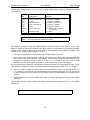
4. Install jumpers for selected options. See the OPTION SELECTION section of this manual.
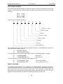
5. Select the base address on the card. See the ADDRESS SELECTION section of this manual.
6. Loosen the nuts on the strain relief bar and swing top end free.
7. Install the card in an I/O expansion slot. If convenient, select a slot, which is adjacent to a vacant
slot, because this will make cable installation easier.
8. Thread the I/O cables, one by one through the cutout in the mounting bracket and plug them into
the headers.
9. Smooth the cables as close as practicable to the card and while holding them close to the card
surface, swing the strain relief bar into position and tighten nuts.
10. Inspect for proper fit of the card and cables and tighten screws. Make sure that the mounting
bracket is properly screwed into place and that there is a positive chassis ground.
11. Replace the computer cover.
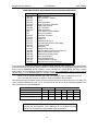
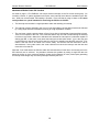
Input/Output connections are via five 50-pin headers on the card. A blank mounting bracket is provided
with units that are marked for CE (European) Certification and, for these units, CE-certifiable cable and
break-out methodology (cables connected to ground at the aperture, shielded twisted pair wiring, etc.)
must be used.
3