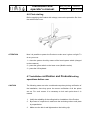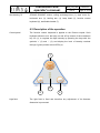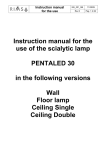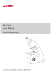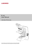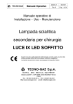
1
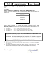
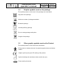
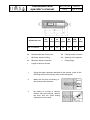
 Installation and
operator’s manual
MIU_010_GB
14/02/12
Rev.4
Page 1 of 34
Installation and operator’s
manual for surgical light
system
Pentaled12
Installation and
operator’s manual
MIU_010_GB
14/02/12
Rev.4
Page 2 of 34
Introduction
Dear user,
You are kindly invited to read this manual carefully before proceeding to
use the Product in order to safeguard yourself and other people from any
injuries.
Mark
This appliance is a Class 1 medical device pursuant to European
Directives on medical devices (MDD) 93/42/EEC, Annex IX, and
2007/47/EC.
Conformity
The manufacturer declares that this product is in compliance with Annex I
(essential requirements of Directive 93/42/EEC and certifies such
conformity by affixing the CE mark.
The Product is classified in risk group 1 according to IEC 62471 standard
(Photobiological Safety of Lamps).
Validity of manual
This operator’s manual refers to the following products:
•
Customer service
Pentaled12
The customer service is at your disposal in case of Product details,
information concerning its use, identification of spare parts being required
and for any other queries you might have concerning the appliance, for
ordering spares and for matters relating to assistance and warranty.
Copyright
•
RIMSA P.LONGONI SRL
•
Via Monterosa 18
•
I-20831 Seregno MB
•
Tel.: ++39 0362 325.709
•
Fax: ++39 0362 328.559
•
Email: [email protected]
The contents of this Manual may be amended by Rimsa, without prior
notice or any further obligations, in order to make changes and
improvements. The reproduction, including partial, or translation of any
part of this manual is forbidden without the written permission of RIMSA.
Installation and
operator’s manual
MIU_010_GB
14/02/12
Rev.4
Page 3 of 34
Right to make changes Rimsa reserves the right to change, cancel or otherwise amend the data
contained in this document at any time and for any reason without prior
notice inasmuch as Rimsa is constantly seeking new solutions which lead
to product evolution. Rimsa therefore reserves the right to make changes
to the supplied Product in terms of shape, fittings, technology and
performances.
Translations
With regard to translations into languages other than Italian, reference
shall always be made to the Italian edition of this operator’s manual.
Installation and
operator’s manual
MIU_010_GB
14/02/12
Rev.4
Page 4 of 34
Declaration of Conformity of the Manufacturer
The company:
RIMSA P. LONGONI S.r.l. Via Monterosa, 18/20/22 - 20831 SEREGNO (MB) - ITALY
Declares under its own responsibility that the Product (Medical lighting device for surgical and
diagnosis use):
PENTALED 12
APPLICARE
ETICHETTA
made by RIMSA P.LONGONI S.r.l., complies with Annex VII of Directive 93/42/EEC dated
14/05/1993, and subsequent amendments (including Directive 2007/47/EC dated 05/09/2007) and
the following standards:
•
•
•
IEC 60601-1
IEC 60601-2-41
IEC 60601-1-2
(Part 1: General requirements for basic safety)
(Part 2: Particular requirements for the basic safety)
(Part 1: General requirements for basic safety – EMC)
Classification with reference to article 9 and Annex IX of Directives 93/42/EEC and 2007/47/EC
DURATION:
Short term (Par.1 “Definitions”, art.1, sub-section 1.1, annex IX)
DESCRIPTION:
Non-invasive medical device (Par.1 “Definitions”, art.1, sub-section 1.2, annex IX)
Active medical device (Par.1 “Definitions”, art.1, sub-section 1.4, annex IX)IX)
CLASS:
•
•
•
I (Par.3 “Classification”, art.1, sub-section 1.1 Rule 1, annex IX)
Reference to technical file Code RIM-FT019.
The conformity assessment is developed with reference to article 11 of Directive 93/42/EEC
and 2007/47/EC.
The RIMSA Quality System complies with UNI EN ISO 9001 and UNI CEI EN ISO 13485
standards and is certified by CSQ (CSQ certificate no. 9120.RMS1 and 9124.RMS2).
Name: Paolo Longoni
Position: Managing Director
Installation and
operator’s manual
MIU_010_GB
14/02/12
Rev.4
Page 5 of 34
Table of Contents
1 General information................................................... 8 1.1 Qualification of operators ........................................ 9 1.2 Packaging, transport, storage and characteristics of
the installation site .......................................................... 9 1.3 Graphic symbols used in the installation manual 10 1.4 Graphic symbols used on the package ................ 11 1.5 Other graphic symbols used on the Product ....... 11 1.6 Warranty Certificate ................................................ 12 2 Precautions for the appliance operator ................. 13 2.1 Technical safety specifications ............................. 13 2.2 Personnel training obligation ................................ 13 2.3 Warranty and liabilities .......................................... 14 2.4 Structural changes or variations ........................... 14 2.5 Disposal after use ................................................... 14 3 Mechanical and electrical arrangement of the site14 3.1 Mechanical arrangement of the site...................... 15 3.2 Electrical arrangement of the site ........................ 17 4 Product installation ................................................... 18 4.1 Ceiling Product installation .................................... 18 Installation and
operator’s manual
MIU_010_GB
14/02/12
Rev.4
Page 6 of 34
4.1.1 Installation of ceiling plate, anchoring tube, power
supply and covering ..................................................... 18 4.1.2 Installation of the structure on the ceiling tube19 4.2 Mobile version Product installation ...................... 19 4.2.1 Installation of stand, power supply and covering
19 4.2.2 Installation of the heeling arm and head .......... 20 4.3 Wall version Product installation ........................... 20 4.3.1 Installation of wall plate and power supply ..... 20 4.3.2 Structure installation.......................................... 20 4.4 Ceiling double version Product installation .......... 21 4.4.1 Installation of ceiling plate, anchoring tube, power
supply and covering ..................................................... 21 4.4.2 Installation of structure to the suspension tube22 4.5 Connecting to electrical plant ............................... 22 4.6 First starting ............................................................ 23 4.7 Installation verification and Products testing
operations before use................................................... 23 5 Importance of personal safety ................................ 24 5.1 Intended use ........................................................... 24 5.2 Environmental conditions ..................................... 25 5.3 Technical safety conditions .................................. 25 Installation and
operator’s manual
MIU_010_GB
14/02/12
Rev.4
Page 7 of 34
5.4 Other safety conditions (secondary effects) ........ 26 6.1 Product description ............................................... 26 6.2 Description of the operation .................................. 27 7 Cleaning and disinfection ....................................... 28 7.1 Cleaning the Product.............................................. 28 7.2 Disinfecting ............................................................. 28 7.3 Sterilizing the handpieces ..................................... 29 7.4 Yearly inspections by the operator ....................... 30 8 Adjustments ............................................................. 30 8.1 Adjustment of the swing arm ................................ 30 8.2 Adjustment of the braking force............................ 31 8.3 Troubleshooting...................................................... 31 8.4 Routine maintenance ............................................. 32 8.5 Spare part list .......................................................... 32 9 Technical data............................................................. 33 Notes .............................................................................. 34 Installation and
operator’s manual
MIU_010_GB
14/02/12
Rev.4
Page 8 of 34
1 General information
IMPORTANT
Product
The ME (Medical-Electrical) EQUIPMENT to which this manual refers is a
LAMP for Operating Theatre or SYSTEM of LAMPS for Operating Theatre
of the PENTALED series and D series. For easier description such ME
EQUIPMENT will be indicated in this manual with the name of “Product”.
CAUTION
This manual is an integral part of the Product as required by European
directive 93/42/EEC and 2007/47/EC. Always keep this installation
manual close to the lamp.
CAUTION
- The Product is not suitable for use in explosion-risk areas
-
The Product is not suitable for use in the presence of inflammable
mixtures of anaesthetics with air, oxygen or NO2 (laughing gas)
CAUTION
RIMSA disclaims all liability for any injuries to persons or damage to
things caused by the installation, maintenance or use of the Product by
unqualified operators. By qualified operator is meant whosoever has
attended a course relating to the installation, maintenance and use of the
product organised by RIMSA or, alternatively, whosoever has carefully
read this installation manual.
CAUTION
The only party responsible for Product installation is the buyer’s customer
itself; no cost or responsibility relating to installation and/or commissioning
of the Product shall therefore be traced back and/or in any case attributed
to RIMSA.
CAUTION
The masonry works involving the preparation of the ceiling or wall, for
Products to be installed on the ceiling or wall respectively, and the electric
works for preparing the power supply system for the Product shall be of a
sturdy and safe nature and completed in a workmanlike manner by
suitably trained personnel.
By way of example only, without limitation, the following professional
figures are deemed adequately trained:
Ö
Building Engineer, Draughtsman, Building firm duly registered in the
professional Register (for masonry works)
Ö
Electro-technician qualified to exercise the profession of electrician
(for the electrical works)
Installation and
operator’s manual
CAUTION
MIU_010_GB
14/02/12
Rev.4
Page 9 of 34
Electrical installation must be made in compliance with the IEC 60364-7710 standard and any national regulations and must contemplate
protection with fuses or thermal magnetic disconnection switch and the
fitting of a master switch able to ensure the complete interruption of the
power supply to the Product.
CAUTION
The Product is a ME EQUIPMENT and consequently falls within the field
of application of the EN:62353 standard. Consequently, any operation
performed on the Product must be carried out in compliance with the
EN:62353 standard, where applicable.
1.1
Operator qualification
Qualification of operators
This paragraph describes the requirements and qualifications which the
operators involved in the various stages of Product life and use must
possess.
Installation
the Product must be installed by a qualified Installer and/or Technician
Use
Professional medical personnel
Routine maintenance
Qualified technician in possession of professional technical requirements
Special maintenance
Qualified technician in possession of professional technical requirements
Assistance
Dealer who has attended a technical course on the Product organised by
the manufacturer
Cleaning
Properly trained medical and paramedical personnel
Demolition
at the end of the Product life cycle, dispose of the used Product in an
environment-friendly way and in compliance with the national directives
applicable to waste disposal.
1.2
Packaging, transport, storage and
characteristics of the installation site
Packaging
Boxes containing the whole structure, with installation manual and user
manual.
Transport
Transport is carried out by any road haulage contractor as long as they
respect the following characteristics:
Temperature (°C): -15 / +60
Installation and
operator’s manual
MIU_010_GB
14/02/12
Rev.4
Page 10 of 34
Humidity: 10 / 75 %
Atmospheric pressure (h/Pa): 500 / 1060
Storage
The devices packaged must be stored (warehoused) in a dry place and at
the following temperature:
Temperature (°C): -15 / +60
Humidity: 10 / 75 %
Atmospheric pressure (h/Pa): 500 / 1060
Installation site
The site appointed for the installation of the equipment must have the
following characteristics:
Temperature (°C): +10 / +40
Humidity: 30 / 75 %
Atmospheric pressure (h/Pa): 700 / 1060 1.3
Graphic symbols used in the installation manual
In this installation manual and on the Product important directions
are marked by means of symbols and identifying words.
Identifying words such as DANGER, WARNING or CAUTION indicate
the classification of the risk of damage.
DANGER signals an immediately dangerous situation which might cause
death or serious damage.
WARNING signals a potentially dangerous situation which might cause
death or serious damage.
CAUTION signals a potentially dangerous situation which might cause
moderate or slight damage.
The following triangular symbol coupled with a side explanation indicates
which danger is being faced:
Electric shock, Mechanical danger due to hanging masses (quick
release of a suspension arm)
Installation and
operator’s manual
MIU_010_GB
14/02/12
Rev.4
Page 11 of 34
1.4
Graphic symbols used on the package
The symbols present on the boxes of the packages are listed below:
High side of the package
Maximum number of packages stackable
Breakable package
Humidity-suffering package
Do not overlap packages with pallet
Weight of the package
1.5
Other graphic symbols used on the Product
The symbols present on the Product are listed below:
B-Type device. Indicates the level of protection against direct and indirect
contact
Graphic symbol proving the CE marking of the product
Symbol indicating the manufacture date (month and year)
Fuses used by the device
Installation and
operator’s manual
MIU_010_GB
14/02/12
Rev.4
Page 12 of 34
1.6
Warranty Certificate
1. The appliance is covered by an 18-month warranty, including electrical parts.
2. The warranty begins on the date of Product shipment from the RIMSA warehouse to the
buyer.
3. In case of disputes, the date indicated on the “transport document” attached to the goods
shall be deemed valid.
4. The warranty only covers the sending of Product spare parts to the buyer or, in the event of
RIMSA considering the replacement of spare parts not feasible, the replacement of the
entire Product, after fabrication faults have been properly ascertained at the undisputable
judgement of RIMSA. The warranty does not therefore cover any other costs or expenses
(including, by way of example but without limitation, labour costs, packaging costs and
transport costs, etc.).
5. The guarantee does not include the components subject to normal wear, such as halogen
bulbs, LEDs, fuses, relays, ball bearings, etc.
6. The warranty does not cover:
- malfunctions due to failure to comply with the instruction manuals;
- malfunctions due to installation and/or maintenance errors;
-
malfunctions or faults caused by carelessness, negligence, incorrect use or other
causes not attributable to RIMSA;
- malfunctions or faults due to the fact that the electrical system of the premises where
the machine is installed is not in compliance with International or local standards for
electrical systems in premises used for medical purposes and similar standards.
7. RIMSA shall repay direct damages suffered by the buyer and which are documented as
attributable to its Product, caused within the warranty period, for an amount not above 40%
of the net value of the product as indicated on the buyer’s invoice. RIMSA’s liability is
expressly ruled out for indirect damages or consequential damages (including cases of the
lamp not being used) deriving from the supply.
8. This warranty certificate replaces legal warranties for faults and non-conformities and rules
out any other possible liability of RIMSA originating from the supplied Products.
9. The payment of any damages to persons or things due to Product malfunction or faults
shall be limited to the maximum amount of RIMSA’s insurance coverage for civil liability.
10. The warranty shall be automatically invalidated in the event of:
- the Product having been tampered with or modified by the buyer or third parties;
Installation and
operator’s manual
MIU_010_GB
14/02/12
Rev.4
Page 13 of 34
- the Product having been repaired by the buyer or third parties, without following the
instructions in the instruction manuals;
- the Product serial number having been cancelled, defaced or removed;
- the buyer not being up to date with payments.
11. For jobs to be done under warranty, the buyer shall contact RIMSA only.
12. The component parts replaced under warranty must only be returned to RIMSA, if so
requested by RIMSA, carriage free and suitably packed.
13. In case of failure to return a part requested by RIMSA, the cost of the component part will
be charged.
14. RIMSA cannot accept returns from end users or in any case from parties other than the
buyer.
15. Products returned to RIMSA must be complete with documentation authorising such return
and another document describing the malfunction.
16. For everything not indicated on this warranty certificate, reference shall be made to the laws
of Italy.
17. For all disputes deriving from or related to the orders to which this warranty certificate
applies and which cannot be amicably settled between the parties, the only competent law
court shall be that of Milan.
2 Precautions for the appliance operator
2.1
Cleaning personnel
Technical safety specifications
The Product cleaning and disinfecting operations described in Chapter 7
must only be performed by duly trained personnel.
Servicing personnel
The inspection and maintenance operations described in Chapter 8 must
only be performed by professional technical personnel.
2.2
Instructing users
Personnel training obligation
Instruct personnel according to the operating instructions as regards
controlling, cleaning and looking after the lamp.
The operator must provide such personnel with written instructions based
on this manual.
Installation and
operator’s manual
MIU_010_GB
14/02/12
Rev.4
Page 14 of 34
2.3
Warranty and liabilities
Rimsa disclaims all liability as regards unreliable Product operation in the
following cases:
-
assembly, changes and repairs not being made by a technician who
has attended a training course on the Product organised by the
manufacturer or by a professional technician,
-
the Product not being used for the purposes for which it was intended,
in compliance with the operating rules and instructions.
2.4
Arbitrary changes
Structural changes or variations
For safety reasons, no arbitrary structural changes or variations to the
Product are acceptable. In case of changes or transformations of this
kind, the manufacturer’s Product warranty shall be invalidated. The
manufacturer thus disclaims all liability for any damage or injuries caused
by any arbitrary structural modifications or variations made or the use of
non-original spare parts.
Only use original
The use of parts not supplied by Rimsa or its dealers shall invalidate the
Rimsa spare parts
warranty.
2.5 Disposal after use
Disposal at the end
The used Product contains valuable materials which can be recycled.
of life cycle
Dispose of the used Product in an environment-friendly way and in
compliance with applicable national directives on waste disposal.
3 Mechanical and electrical arrangement of
the site
NOTE
The building and electrical arrangement works for the installation of the
Product are the responsibility of the Final Customer.
Installation and
operator’s manual
MIU_010_GB
14/02/12
Rev.4
Page 15 of 34
3.1
DANGER
Mechanical arrangement of the site
The building slab arrangement works to install the Product must be
carried out in a solid and safe way according to the standards by qualified
personnel.
By qualified personnel we mean, including but not limited to, the following
professionals: Building Engineer, Surveyor, Building Contractor, duly
registered with the Professional Register.
DANGER
In case of improper drilling, e.g. drilling of a piece of iron of the reinforced
concrete, the technician responsible for the construction will have to be
informed for safety reasons, since the statics of the premises might be
compromised.
CAUTION
The ceiling must have a capacity of at least 300 Kg/m2 and a thickness of
at least 250 mm.
The installation site must be declared fit for use.
After making sure that the site used as medical premises complies with
the requisites required above, proceed to the mechanical anchorage of
the ceiling plate determining the type of ceiling for the anchorage and
acting accordingly.
The installer assumes all responsibility, technical, civil and legal, related to
the correct and suitable arrangement of the anchorage and installation of
the Product, which must be carried out according to the standards.
Fixing positions
The Product is supplied complete with ceiling attachment (tiges + counter
plate)/ wall attachment (wall plate). Tiges length varies in relation to the
height of the premises in which the Product is to be installed.
The
anchoring tube is calculated to install the Product at a finished height from
the floor to the cupola of the Product with the oscillating arm in a
horizontal position of about 190/200 cm, save a different request from the
client.
As a non-exhaustive example, we list some of the types of slab:
Reinforced concrete
Mechanical anchorage: fix the ceiling plate by means of 6 screw anchors
Hilti HSL-3-G M8/20 following the directions given by the insert
manufacturer scrupulously and listed below for information:
Installation and
operator’s manual
MIU_010_GB
14/02/12
Rev.4
Page 16 of 34
Anchor tie-rod
HSL-3-G M8/20
do
(mm)
t
(mm)
hs
(mm)
l
(mm)
Mt
(Nm)
SW
(mm)
x
(mm)
12
80
60
98
25
13
20
do
Nominal diameter of the point
Mt
t
Minimum depth of drilling
Sw Opening of the spanner
hs
Minimum depth of insertion
l
Length of anchor tie-rods
x
Closing torsion moment
Fixing height
1.
Using the paper template attached to this manual, mark all the
8/6 fixing holes of the chosen point of the ceiling/wall.
2.
Make the first hole according to
the safety anchor diameter.
3.
By means of a pump or vacuum
cleaner with pipe terminal, remove
the dust and the small drilling
fragments from the hole.
Installation and
operator’s manual
MIU_010_GB
14/02/12
Rev.4
Page 17 of 34
4.
The anchor tie-rod must be
inserted into the hole keeping it to
axis and using a hammer.
Attention!
Consider the insertion depth.
5.
By the hexagonal dynamometrical
spanner tighten with spanner
adjusted at the value specified by
the constructor of the anchors,
opening the anchor.
The anchor tie-rod will immediately
take the weight.
6.
Make the remaining 7/5 holes and insert the anchor tie-rods as
in previous points 2– 5.
7.
After one hour, tighten the anchor tie-rods again with the
tightening torque prescribed.
Chemical anchorage: fix the tiges with n° 8/6 chemical injection anchors
mod. Hilti HIT-HY 150 with HAS following the directions given by the
manufacturer Hilti scrupulously.
After arranging the chemical anchors to the CEILING/WALL, fix the tiges
with nuts and lock nuts for each tie-rod and tightening with the hexagonal
dynamometrical spanner you will tighten with spanner adjusted at the
value specified by the constructor of the anchors.
Clay-cement mix
In this case it is compulsory to enclose the slab sandwich-like by the
Product plate and the counter-plate.
Plate and counter-plate must be enclosed to each other with M8 steel
threaded bars each, blocked at the upper and lower ends by respective
washers, nuts and lock nuts.
3.2 Electrical arrangement of the site
DANGER
The electrical system arrangement works of the site used as medical
premises to power the Product must be carried out in a safe way
according to the standards by qualified personnel.
By qualified personnel we mean, including but not limited to, the following
professionals:
Electro-technician licensed to practise as electrician
Installation and
operator’s manual
DANGER
MIU_010_GB
14/02/12
Rev.4
Page 18 of 34
Before installing the Product check the following conditions:
the electrical system of the installation site must comply with the national
laws and/or regulations in force for electrical systems in sites used as
medical premises;
the electrical system must be certified by an electrician licensed to issue
the conformity certificate;
the verification of the grounding circuit must be certified as required by the
norms in force.
4 Product installation
Before installing the Product, make sure that all the packages are
present and in good condition, without any transport-related
damage, and that the contents correspond to what is specified
above.
Claims will be considered only if the seller or the forwarder are
informed immediately. Each claim must be in writing. Goods are
always carried at the buyer’s risk.
Keep the original package in case the lamp must be sent back.
4.1 Ceiling Product installation
4.1.1
Installation of ceiling plate, anchoring tube, power
supply and covering
ATTENTION
Incorrect plate levelling may cause the horizontal arm of the Product to
make an undesired spontaneous move, when passing from the nonbalance condition to the balance one.
See drawing 52
Position the template sheet (drawing 51) (2) on the ceiling (1) fixing it with
adhesive tape (3).
Make the 8 holes following what is prescribed in paragraph 3.1
See drawing 53
After making the holes on the ceiling (1), fix the plate (2) to the ceiling by
nuts and lock nuts (3).
See drawing 54
Fix the anchoring tube (1) to the threaded pins of the ceiling plate (2) by
nut and lock nut (3), ensuring the correct rod levelling by means of a spiritlevel (4).
See drawing 55
The anchoring tube (1) is supplied with a standard size of 100cm. Using a
jigsaw (2), cut the tube to the desired size in relation to the height of the
Installation and
operator’s manual
MIU_010_GB
14/02/12
Rev.4
Page 19 of 34
room (cut the tube from the side (3) opposite to the one with the fixing
holes (4) of the horizontal arm).
To determine the correct length of the tube use the table given (the
recommended height between floor and lamp head is 200cm).
See drawing 56
Insert the anchoring tube (1) down to beat into the ceiling plate hub (2)
(keeping the cut side upwards); to lock it, tighten screw (3), the serrated
washer (5) and the nut (4), thus exerting a hub pressing action and
allowing the tube tightness.
See drawing 57
By a drill (1), make a 7mm diameter hole on the tube side near the nut M8
(2) welded on the plate hub; then insert and screw the M8 conical-pointed
dowel supplied in the nut (3) until its conical point presses against the hole
previously obtained in the anchoring tube.
DANGER – Product falling danger
See drawing 58
Make sure that the Product power supply cable (1) can reach the power
supply board (2) of the Product without creating interferences with the
anchoring tube.
Then position the cover (3) and the relevant locking ring (4).
4.1.2
See drawing 59
Installation of the structure on the ceiling tube
Insert the connection cables (7) along the anchoring tube making them
out from the tiges plate so they can reach the connection terminals of the
electrical panel.
Align the horizontal arm pin (3) with the anchoring tube (4).
Connect the connectors (1) and (2).
Insert the pin into the tube fitting in the relevant fixing holes, and fix it
screwing in the four screws (5) using a hexagonal wrench (6).
4.2 Mobile version Product installation
4.2.1
See drawing 60
Installation of stand, power supply and covering
Remove the bolt (2) from the stand bottom (1).
Installation and
operator’s manual
MIU_010_GB
14/02/12
Rev.4
Page 20 of 34
Mechanical connection
Position the stand (1) on the base (5) fitting and inserting its pawl (6) into
the plate seat (7), use the bolt previously unscrewed to join the stand to
the base and tighten thoroughly.
Insert the cover (3) from the stand top and the relevant connecting clip (4).
WARNING – Instability and falling danger
Failure to insert the detent into the appropriate seat present on the
basement plate implies the risk of instability and the possible fall of the
structure.
4.2.2
See drawing 61
Installation of the heeling arm and head
Align the heeling arm pin (8) with the floor stand (1).
After connecting the electric cable terminals (9) to (10) each other, insert
the heeling arm pin into the stand fitting in the holes (11) with those of the
stand (12) and screw in the two locking screws (13) by a screwdriver.
4.3 Wall version Product installation
4.3.1
ATTENTION
Installation of wall plate and power supply
Incorrect plate levelling may cause the horizontal arm of the lamp to make
an undesired spontaneous move, when passing from the non-balance
condition to the balance one.
See drawing 66
Position the template sheet (drawing 11) (2) on the wall (1) fixing it with
adhesive tape (3).
Make the 6 holes following what is prescribed in paragraph 3.1
See drawing 67
After making the holes on the wall (1), following what is prescribed in
paragraph 3.1, fix the plate (2) to the ceiling ensuring the correct plate
levelling by means of a spirit-level (3).
4.3.2
See drawing 68
Structure installation
Align the horizontal arm pin (1) with the anchoring tube (2).
Connect the connectors (3) and (4).
Installation and
operator’s manual
MIU_010_GB
14/02/12
Rev.4
Page 21 of 34
Insert the pin into the tube fitting in the relevant fixing holes, and fix it
screwing in the four screws (5) using a hexagonal wrench (6).
4.4 Ceiling double version Product installation
4.4.1 Installation of ceiling plate, anchoring tube, power
supply and covering
ATTENTION
Incorrect plate levelling may cause the horizontal arm of the Product to
make an undesired spontaneous move, when passing from the nonbalance condition to the balance one.
See drawing 52
Position the template sheet (drawing 51) (2) on the ceiling (1) fixing it with
adhesive tape (3).
Make the 8 holes following what is prescribed in paragraph 3.1
See drawing 53
After making the holes on the ceiling (1), fix the plate (2) to the ceiling by
nuts and lock nuts (3).
See drawing 69
Fix the anchoring tube (1) to the threaded pins of the ceiling plate (2) by
nut and lock nut (3), ensuring the correct rod levelling by means of a spiritlevel (4).
See drawing 70
The anchoring tube (1) is supplied with a standard size of 96 cm. Using a
jigsaw (2), cut the tube to the desired size in relation to the height of the
room (cut the tube from the side (3) opposite to the one with the fixing
hubs (4) for the horizontal arm); you should not cut the pipe below a
length of 30 cm in order to facilitate the subsequent installation operations
To determine the correct length of the tube use the table given (the
recommended height between floor and lamp head is 200cm).
See drawing 71
Insert the cover (1) on the suspension tube (2) and then, insert the
suspension tube down to beat into the ceiling plate hub; to lock it, tighten
screw (3), the serrated washer (4) and the nut (5), thus exerting a hub
pressing action and allowing the tube tightness.
See drawing 72
By a drill (1), make a 7mm diameter hole on the tube side near the nut M8
(2) welded on the plate hub; then insert and screw the M8 conical-pointed
dowel supplied in the nut (3) until its conical point presses against the hole
previously obtained in the anchoring tube.
Installation and
operator’s manual
MIU_010_GB
14/02/12
Rev.4
Page 22 of 34
4.4.2
See drawing 73
Installation of structure to the suspension tube
Align the horizontal arm pin (1) with the anchoring tube (2).
Connect the connectors (3) and (4).
Insert the pin into the tube fitting in the relevant fixing holes, and fix it
screwing in the four screws (5) using a hexagonal wrench (6).
Repeat the same operations for the second horizontal arm.
At the end of the installation close the openings of the support tube
through supplied silicone caps (7).
4.5 Connecting to electrical plant
DANGER – Danger of electric shock
Before connecting, make sure that the electrical system line is NOT under
tension.
The Product power supply group (support sheet, feeder, terminal board) is
firmly fixed to the plate of the anchoring tube, to the base or to the wall
box in case of a ceiling, mobile or wall version device respectively.
As regards the connection of the electrical system line (F,N) and the lamp
cables (+,-,T) follow what is specified in the specific wiring diagram
attached.
Fuses
The device fuse protection is ensured by installing, on the input line (F,N),
two fuses type: 5x20 T.1A (for 230V~) or 5x20 T.2A (for 110V~)
See drawing 62
As for floor versions it is necessary to connect wires by the electric panel
of the device; to do it, lift the connecting ring (1) and the cover (2). Now
connect the connectors (3) (4) and (5) (6). Then reinstall the cover and the
connecting ring and fix the cover by a screwdriver (7) tightening the screw
M4 (8) and gripping inside the threaded bush (9) present on the electric
panel support.
CAUTION – Irreparable damage to the Product
In the case of ceiling versions, the fuse protection to the electric panel
terminals must be inserted ONLY AFTER completing the mechanical and
electrical assembly of the Product.
Advance insertion may cause irreparable damage to the light source. If
the product is not used for long periods, remove the fuses.
Installation and
operator’s manual
MIU_010_GB
14/02/12
Rev.4
Page 23 of 34
4.6 First starting
Before supplying the Product with voltage, remove the protection film from
the mobile base cover.
ATTENTION
Now it is possible to power the Product to make sure it gives out light. To
do so you must:
1 – close the system circuit by means of the head system switch (charged
to the customer)
2 – press the green switch on the base cover (Mobile version)
3 – press the I/O keyboard
4.7 Installation verification and Products testing
operations before use
CAUTION
The following notes are to be considered compulsory during verification of
the installation, since they prove the correct verification of all the points
set out. For such reason it is necessary to tick each point when it is
treated.
1.
Verify the suitability of the ceiling/wall on installation of the Product
2.
By means of a spirit-level, make sure the anchoring tube or wall plate
is perpendicular
3.
Make sure the bolt is well tightened on the locking clip
Installation and
operator’s manual
MIU_010_GB
14/02/12
Rev.4
Page 24 of 34
4.
Check the hole and make sure the safety dowel is inserted on the
anchoring tube
5.
Make sure the 4 screws M4 supporting the horizontal arm (ceiling and
wall version) are well tightened
6.
Make sure the mobile stand pawl is properly inserted into the relevant
base seat
7.
Check the Product earthing and make sure the earthing terminals are
well tightened
8.
Make sure the movement mechanism works perfectly. Check the
mechanical operation of the Product by directing and rotating it and
make sure that all movements are frictioned so that the Product is
stable in any position and does not lose its position
9.
After turning on the Product, it must give out light from the cupola
Seal and signature of the installer:
___________________________________________________________
5 Importance of personal safety
5.1 Intended use
Use in compliance with
standards
The Product is made to light up the area occupied by the patient
undergoing surgery or observation and has been designed for use in
operating theatres or medical surgeries.
Field of work
The Product correctly lights up the field of work from a distance of about
70 – 140 cm from the point of operation.
Single lamp:
Definition
In compliance with the IEC60601-2-41 standard, a single lamp
(PENTALED12) is a secondary scialytic lamp for surgery and can only be
used in operations where the interruption of lighting does not cause risks
for the patient.
Installation and
operator’s manual
MIU_010_GB
14/02/12
Rev.4
Page 25 of 34
System of operating lamps:
Definition
In compliance with the IEC60601-2-41 standard, a system of lamps made
up of several lamp units can be used to locally light up the patient’s body
without any limitation. It is also suitable for continuous function.
It enables the surgeon to operate also in the most difficult conditions of
visibility. It is intended to make treatment and diagnosis possible and to be
used in operating theatres.
Undesired effects
If the light fields of several lamp units are superimposed, there will be an
caused by
increase in heat in the patient area with consequent dehydration of tissues
superimposition of
and, above all in the case of prolonged operation and reduced blood
light fields
supply, considerable damage to tissues.
If reduced blood supply or the start of tissue dehydration occurs, reduce
the light intensity.
5.2 Environmental conditions
-
The Product is not suitable for use in explosion-risk areas.
-
The Product is not suitable for use in the presence of inflammable
mixtures of anaesthetics with air, oxygen or NO2 (laughing gas).
-
During operation, the ambient temperature must be between 10°C
and 40°C.
-
Relative humidity must be between 30% and 75%.
-
Atmospheric pressure must be between 700 and 1060hPa.
5.3 Technical safety conditions
The safe use and proper operation of the Product is ensured if:
Safe fastening
The lamp is safely fastened to the ceiling/wall from a static viewpoint and
a static stability test exists,
Wiring systems
The wiring systems of the premises involved are in compliance with
applicable local regulations,
Authorised personnel
Changes to the Product or maintenance jobs are performed by personnel
trained by Rimsa or by a professional technician
Correct assembly
The Product has been installed following currently valid installation
and start up
instructions and has been started up by a professional installer,
With regard to assistance, repairs, structural changes and additional
Original spares
accessories, only original Rimsa spare parts are used.
Installation and
operator’s manual
MIU_010_GB
14/02/12
Rev.4
Page 26 of 34
5.4 Other safety conditions (secondary effects)
Optical safety
- Do not direct the light source into the patient’s and/or operator’s eyes.
- Obligation to adequately protect the patient’s eyes.
Failure to follow such precautions could cause glare and potential damage
to the retina.
Incorrect use
- Never place and/or hang anything on the Product.
Unless this precaution is taken, positioning will not be reliable and the
danger exists of such objects falling in the operating area.
- Never hang on the Product with the body weight of a person.
Unless this precaution is taken, mechanical parts of the Product could be
damaged.
Covering the heads
- Never cover the head of the Product during operation.
Failure to comply could prevent heat exchange with the environment and
the Product could overheat.
Knocks
- Avoid knocking the rocker arms and Product head.
A violent knock could damage the Product and pieces of paint could chip
off and fall onto the operating field in the patient area.
6 Product description and operation
6.1 Product description
Versions
See drawing 63
The Product is available in different versions:
-
mobile
-
ceiling
-
wall
-
ceiling double
MOBILE version: wheel base (1), stand (2), stand extension (3), heeling
arm (4), lamp head (5), function control keyboard (6), sterilizable handle
(7), power supply plug (8).
See drawing 64
CEILING version: ceiling anchoring tube (1), ceiling cover (2), horizontal
arm (3), heeling arm (4), lamp head (5), control keyboard (6), sterilizable
handle (7).
See drawing 74
WALL version: wall box (1), horizontal arm (2), heeling arm (3), lamp head
(4), function control keyboard (5), sterilizable handle (6).
See drawing 75
Installation and
operator’s manual
MIU_010_GB
14/02/12
Rev.4
Page 27 of 34
CEILING DOUBLE version: ceiling anchorage tube (1), tiges cover (2),
horizontal arm (3), heeling arm (4), lamp head (5), function control
keyboard (6), sterilizable handle (7).
6.2 Description of the operation
Control panel
The function control keyboard is applied to the Product cupola. Such
keyboard allows to turn the lamp on and off by means of the membrane
key I/O (1), to regulate the light intensity by pressing the keys with the
symbols ‘+’ (2) and ‘-‘ (3), and display the level of intensity reached
through 3 green position micro-LEDs (4).
1
4
2
Light field
3
The light field is fixed and therefore any adjustment of its diameter
dimension is prevented.
Installation and
operator’s manual
MIU_010_GB
14/02/12
Rev.4
Page 28 of 34
7 Cleaning and disinfecting
7.1 Cleaning the Product
CAUTION – Electric shock hazard
Switch the Product off by means of the operating theatre main switch and
make sure it cannot be switched back on.
Protect the Product against water spray and do not clean it/disinfect it with
liquids.
Leave the lamp body to cool down. Only clean the lamp body when it is
cold.
Clean with appropriate detergent with low alkaline content and chlorine
free.
IMPORTANT
Do not use abrasive products, petrol, paint thinners, alkaline detergents,
acids, containing alcohol or aldehydes;
Dose the detergents so no liquids penetrate into the lamp bodies and into
the support arm system.
Clean the Product with a damp but not wet cloth.
7.2 Disinfecting
CAUTION – Electric shock hazard
Switch the Product off by means of the operating theatre main switch and
make sure it cannot be switched back on.
Protect the Product against water spray and do not clean it/disinfect it with
liquids.
Leave the lamp body to cool down. Only disinfect the lamp body when it is
cold.
CAUTION
Disinfectants can contain substances which are harmful for the health:
only use disinfectants in accordance with the rules on hygiene established
by the hospital.
Installation and
operator’s manual
MIU_010_GB
14/02/12
Rev.4
Page 29 of 34
The Product operator must comply with the rules established by the
national commission for hygiene and disinfection.
IMPORTANT
To prevent damaging parts in stainless steel or aluminium, only use
disinfectants which are chlorine and halogen free.
To prevent the plastic parts becoming fragile, use only disinfectants with
low alcohol content.
Dose the disinfectants so no liquids penetrate inside the lamp bodies and
into the support arm system.
Clean the Product with a damp but not wet cloth.
7.3 Sterilizing the handpieces
CAUTION – Hazard for the patient
Replace the handpieces as soon as these become cracked or deformed,
as these could fall in the wound area.
The Product operator must comply with the rules of the national
commission for hygiene and disinfection.
Handpiece fitting / removal:
- press the two lateral safety keys of the handle and extract the handle
itself.
- insert the handle till the bottom until the safety keys don’t fall in their
seats.
Cleaning, disinfecting and sterilizing the handpiece:
The handpieces are made of plastic material resistant to heat and knocks
(PPSU).
They can be cleaned with a lightly-alkaline detergent free of active
chlorine.
To disinfect the handpieces, we suggest using alcohol or aldehyde-based
products. The disinfectants must be approved by the manufacturer for use
on polyphenylsulfone (PPSU).
Before sterilizing, rinse the handpieces.
The handpieces can withstand about 300 steam sterilization cycles as
follows:
or
steam sterilization at 121°C 1.3bar from 25 to 30 minutes,
Installation and
operator’s manual
MIU_010_GB
14/02/12
Rev.4
Page 30 of 34
-
steam sterilization at 134°C 2.3 bar for 4 minutes.
Position the handpieces straight with open side downwards.
Do not exceed a sterilization temperature of 134°C.
Avoid the handpieces coming into contact with other objects during the
disinfection process.
Each Product, over time, is subject to a certain amount of wear.
Product safety and operation must therefore be checked during
inspection and maintenance intervals.
7.4 Yearly inspections by the operator
IMPORTANT
Keep to the yearly inspection schedules and inspect the product
according to IEC 62353 standard.
8 Adjustments
8.1 Adjustment of the swing arm
See drawing 65
The Product is sold already balanced and does not require further
adjustment. In the event of the swinging arm with spring balancing
becoming stiff or loose over time, mechanical intervention is possible by
regulating the compression of the internal spring.
Slide the rubber grommet forward (1) and the cover (2) along the heeling
arm (3). Insert a pin (4) having maximum diameter of 4mm into the holes
of the ring nut (5) and rotate in the directions of the arrows to
increase/decrease the charge of the spring.
If the heeling arm lowers, the elastic force of the spring is insufficient:
-
rotate the lever downwards to charge the spring.
If the heeling arm still goes up, the elastic force of the spring is too high:
-
rotate the lever upwards to discharge the spring.
After making adjustments, return the covering to its original position.
Installation and
operator’s manual
MIU_010_GB
14/02/12
Rev.4
Page 31 of 34
8.2 Adjustment of the braking force
See drawing 65
As for all the mechanic parts, brakes also are subject to wear and tear.
If the lamp body does not automatically keep the position it is put to, it is
necessary to adjust the braking force by acting on the screws of the
brakes.
Horizontal arm brakes
Use a 2.5 hexagonal wrench (7) to increase the braking force, rotating the
arm brake dowels (6) clockwise.
8.3 Troubleshooting
no.
Problem
1
The Product does not remain in
position
2
The Product fails to work
3
4
The fuse continues to burn out
The light flickers and produces a
stroboscopic effect
5
The light beam on the operating field
is not focalised (defective meeting of
light fields)
6
The Product does not switch on
Solution
Make sure the plate fitted on the wall (wall) is
perfectly flat, that the stem is flat on the base (mobile)
and that the tube secured to the ceiling (ceiling) is
level.
Further tighten the brakes on the joints so as to
increase friction.
Check the presence of the fuses inside the terminal
box (T1A for 230V~ or T2A for 110V~), the hooking of
the electrical connectors. Check the presence of
voltage in the lamp head
Check the characteristics of the fuses inserted
T1A with 230VAC
T2A with 100VAC
Contact the service center
Contact the service center.
Check the power supply voltage and fuses.
Electronics are damaged: contact the service center
Installation and
operator’s manual
MIU_010_GB
14/02/12
Rev.4
Page 32 of 34
8.4
no.
1
2
Routine maintenance
Job
Period
Inspect all the lamp joints and make sure they do not squeak. If
they do, add white grease to the clutches involved. If the
Product does not maintain the position, adjust the clutches. To
determine which clutches to adjust, see point 6.2.
Every 6 months
Make sure the Tiges retention screws are tightened properly.
Also check the 6 horizontal arm retention screws and the 3
swing arm screws.
If these are not properly fastened, adequately tighten.
Once a year
Check the integrity of the leads from the PCB to the board and
that these are fastened properly.
If they are not, proceed to correctly tighten.
INTERRUPT THE POWER SUPPLY BEFORE PERFORMING
THESE OPERATIONS.
3
Once a year
4
Once a year
Make sure the line voltage is correct. Make sure 24V are
reaching the board.
5
Once a year
Check the condition of the Product paint. Make sure there are
no paint pieces that could fall on the operating field.
8.5 Spare part list
Description
Order code
Sterilizable handle
Z180045
Electronic card PENTALED 12
Z300617
Electronic card
Z300220
Installation and
operator’s manual
MIU_010_GB
14/02/12
Rev.4
Page 33 of 34
9 Technical data
Technical data on light
Illumination Ec at a distance of 1 m [Lux] ±10%
PENTALED 12
50.000
Color temperature [K] ±5%
5.000 K (±5%)
Color rendering index Ra [-]
90
Diameter of the light field d50 [mm]
85
Diameter of the light field d10 [mm]
140
Illumination depth [mm]
1500
Maximum irradiation [W/m2]
119
Irradiation / Illumination [mW/m2lx]
2,38
Maximum irradiation in the UV [W/m2]
0,001
Focus by handle
No
Data on electrical connection
Primary alternating voltage [Volt ac]
Frequency [Hz]
100÷240
50/60
Absorbed power [VA]
40
Light source
N°12 Led x 2W
LED light source duration [h]
(this datum can vary according to voltage peaks and the
frequency of use)
Light intensity control
50.000
50 - 100
General data
Color
RAL 9003
Directive
93/42/EEC (included 2007/47/EC)
Standard
EN 60601-2-41
Installation and
operator’s manual
MIU_010_GB
14/02/12
Rev.4
Page 34 of 34
Electrical safety class
Class I
Protection against direct and indirect contacts
B-type device
Dimensions
Lamp body diameter [cm]
30
Diameter of the poly-elliptical reflector [cm]
5,5
Light emission surface [cm2]
285
Scialytic mobile, ceiling, wall, ceiling double lamp weight
[Kg]
18; 13; 11; 20
Certificates
Complying with directive 93/42/EEC
(included 2007/47/EC)
Notes
n9
168
D
184
D
C
368
C
B
184
B
A
Disegno di dima per l'esecuzione dei 6 fori dis.11
(drawing to be used to do 6 holes, dwg n.11
Formato A3
(A3 format)
A
Drawing code
11
CEILING PLATE SHEET TEMPLATE
DIMA PIASTRA A SOFFITTO
(SCALE 1:1)
1
8
2
7
3
6
4
5
SHEET FORMAT: A3
Drawing code
FORMATO FOGLIO: A3
Rev.
Data
051
1
2
3
Drawing code
Rev.
Data
052
1
2
3
Drawing code
Rev.
Data
053
2
3
1
4
Drawing code
Rev.
Data
054
2
A
A
1
B
B
Tube length list [mm]
1
Tabella lunghezze tubo [mm]
3
4
L
2000
H
L
H [mm]
2570
2600
2650
2700
2750
2800
2850
2900
2950
3000
3050
3100
3150
3200
3250
3300
3330
L [mm]
200
230
280
330
380
430
480
530
580
630
680
730
780
830
880
930
960
Drawing code
Rev.
Data
A
23/04/2012
055
A
2
1
5
A
3
4
Drawing code
Rev.
Data
056
1
2
3
4
Drawing code
Rev.
Data
058
4
A
1
2
3
A
6
7
5
Drawing code
Rev.
Data
059
4
2
1
5
3
1
2
A
7
6
Drawing code
A
Rev.
Data
061
8
11
13
9
A
10
1
12
A
Drawing code
Rev.
Data
061
2
1
3
5
A
6
4
A
8
7
Drawing code
9
Rev.
Data
062
4
3
5
2
8
1
6
7
Drawing code
Rev.
Data
063
3
2
1
5
4
A
7
A
6
Drawing code
Rev.
Data
064
6
7
2
1
6
7
A
3
5
A
4
Drawing code
Rev.
Data
065
4
1836
mm
2360mm
2
3
1
Drawing code
Rev.
Data
A
23/04/2012
066
3
1
2
Drawing code
Rev.
Data
067
A
4
1
2
3
A
B
B
5
6
Drawing code
Rev.
Data
068
2
3
1
4
Drawing code
Rev.
Data
069
2
A
A
1
B
B
Tube length list [mm]
Tabella lunghezze tubo [mm]
1
3
4
L
2000
H
L
H [mm]
2700
2750
2800
2850
2900
2950
3000
3050
3100
3150
3200
3250
3300
3350
3400
L [mm]
300
350
400
450
500
550
600
650
700
750
800
850
900
950
1000
Drawing code
Rev.
Data
070
1
2
A
3
4
A
5
Drawing code
Rev.
Data
071
A
1
2
A
3
Drawing code
Rev.
Data
072
A
7
5
6
2
7
4
3
1
Drawing code
A
Rev.
Data
073
4
A
2
6
3
1
A
5
Drawing code
Rev.
Data
074
2
3
1
3
4
A
7
5
4
7
A
5
6
Drawing code
Rev.
Data
075