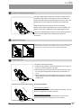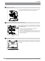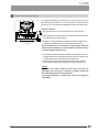
1
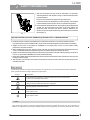
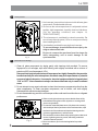
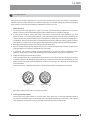
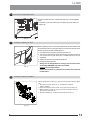
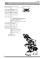
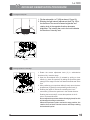
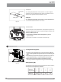
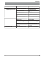
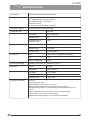
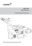
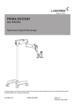
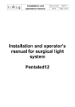
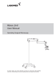
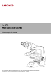
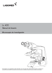
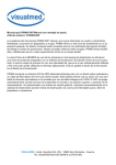
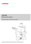
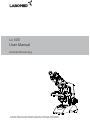
R
Lx 300
User Manual
Clinical Microscopy
To ensure proper use of this instrument as well as to avoid injury while operating
instrument, understanding this manual completely before use is highly recommended.
CONTENTS
1
INTRODUCTION
1
2
SAFETY INFORMATION
3
Lx 300 BINOCULAR
5
4
UNPACKING YOUR MICROSCOPE
6
5
STANDARD COMPONENTS
7
6
OPTIONAL ACCESSORIES
7
INITIAL SETUP
8
ASSEMBLY
9
SUMMARY OF BRIGHTFIELD OBSERVATION PROCEDURE
10
DETAILED OBSERVATION PROCEDURE
15-19
11
TROUBLESHOOTING GUIDE
20-21
12
SPECIFICATIONS
2-4
8-10
11
12-13
14
22
INTRODUCTION
The Lx 300 is a clinical microscope reflecting a modern design as well as the latest in optical and
mechanical advancements. Designed for professionals as well as clinicians, this microscope offers
many features and functions with excellent ergonomics for a fatigue free usage . Here are few points
highlighting the benefits of the Lx300:
- Extra clarity and contrast is provided through a 360° rotatable Binocular body inclined at 45° with IPD
and height adjustment.
- The pressure die cast stand consists of ball bearing, frictionless sideways focusing to avoid any loss
in motion.
- All painted surfaces are with anti-microbial properties.
- The sturdy new stylish design provides a high degree of comfort as well as stability.
- The high powered objectives are spring loaded to prevent accidental damage to specimen slides.
- The quadruple nosepiece has a comfortable ribbed grip for easy rotation that also safeguards the
turret system against any damage. All positions are par-centered and par-focalised ensuring the
highest level of accuracy.
- The ball bearing mechanical stage allows smooth travel over a 78 x 54mm area with spring loaded
stage clamps for retaining the specimen at the exact position desired. A 0.1mm vernier scale
provides accurate location of specimen area.
- High power illumination is delivered through our well crafted Universal Power Supply and operates
with any 100V- 240V AC input. The LED configuration is operational with an in-built rechargeable
battery P/N 9135000-902, which when plugged in, draws power from a Universal Power Supply
operating at 100V-240V Ac input. This ensures continuous operation even under fluctuating
voltages.
- Our Halogen bulb (6V-20W) has an average life span of up to 2,000 hours. Our LED has an average
life span of up to 60,000 hours.
- The Lx 300 comes equipped with a removable N.A. 1.25 Abbe condenser with aspheric lens for
brighter illumination levels, and an iris diaphragm for better resolution and contrast control.
1
Lx 300
SAFETY INFORMATION
1. After the microscope has been used for observation of a specimen
containing bacteria, clean all parts coming in contact with the specimen
to prevent infection.
¡
¡
Be sure to remove the specimen before moving this product.
In case the specimen is damaged by erroneous operation, it is important
to clean all surfaces that may have come in contact with the specimen.
2 To avoid potential electrical hazards when replacing either halogen bulb
or LED, turn the microscopes main switch to the OFF position and
disconnect power cord from wall outlet in advance. Whenever you
replace your microscope bulb, allow lamp socket and bulb to cool before
touching (Fig. 1)
Fig. 1
Applicable bulb/LED replacement: 6V20W Halogen bulb P/N CX-013 or LED P/N 9135000-901
3. Install microscope on a sturdy, level table or bench and avoid any restriction of air vents in the base of the unit.
Do not place microscope on a flexible surface, as this could result in blocking the air vents and cause overheating.
4. Always use the power cord provided by LABOMED. If the proper power cord is not used, product safety
performance cannot be warranted.
5. When installing the microscope, route the power cord away from the microscope frame. Should the power cord
come in contact with the microscopes base, the power cord could melt due to overexposure to heat.
6. Always ensure that the grounding terminal of the microscope and that of the wall outlet are properly connected. If
the unit is not grounded, LABOMED can not warrant electrical safety.
7. Never allow metallic objects to penetrate the air vents of the microscope frame as this could result in user injury and
damage to the microscope.
8. After operation of microscope, be sure to disconnect power cord from connector socket of the microscope or from
the wall power outlet.
Safety Symbols
The following symbols are found on the microscope. For optimal use, it is recommended that users understand
these symbols and always use the equipment as prescribed.
Symbol
Explanation
This surface has a tendency to heat up and should not be touched unless
system has completely cooled down.
!
Before use, carefully read the instruction manual. Improper use could result in
injury to the user and/or damage to the equipment.
Warning against risk of electric shock.
Main switch is ON.
Main switch is OFF.
Caution
If the microscope is used in a manner not specified by this manual, the safety of the user may not be warranted. In
addition, the equipment may also suffer damage. Always use the equipments as outlined in this instruction manual.
2
Lx 300
1
Getting Started
1. A microscope is a precision instrument with delicate glass
components. Please handle with care.
2. Do not use the microscope where it is subjected to direct
sunlight, high temperature, humidity, dust and vibrations.
(For the operating conditions, see chapter 14,
"SPECIFICATIONS")
3. The microscope is ventilated by natural convection. Be
sure to leave enough space (10 cm or more) around body
when installing the unit.
4. Arm handle is provided for carrying the microscope.
To prevent damage, do not hold the microscope by the
stage or observation tube.
Be sure to remove the specimen from the stage clip
while transporting unit to avoid damage to the
specimen slide.
Fig. 2
2
Maintenance and Storage
1. Clean all glass components by wiping gently with cleaning cloth provided. To remove
fingerprints or oil smudges, wipe with cleaning cloth slightly moistened with a mixture of
petroleum (85%) and isopropanol (15%).
Since solvents such as petroleum and isopropanol are highly flammable, they must be
handled carefully. Be sure to keep these chemicals away from open flames or potential
sources of electrical sparks - for example, electrical equipment that is being switched
“ON” or “OFF”. Also remember to always use these chemicals only in a well-ventilated
room.
2. Do not attempt to use organic solvents to clean the microscope components other than the
glass components. To clean non-glass components, use a lint-free, soft cloth slightly
moistened with a diluted neutral detergent.
3. Do not disassemble any part of the microscope as this could result in malfunction or mitigated
performance.
1
Fig. 3
3
4. When not using the microscope, ensure that the frame is fully
cooled before storing the unit in a dry locker or covering with a
dust cover (provided).
5. To clean the condenser/phase turret, fully loosen the screw(1)
with the help of allen key and remove the condenser then, wipe
the front lens of the condenser with optical cleaning solution
(mixture suggested above) and lens tissue.
The condenser can be re-attached by replacing the condenser in
its seat, tightening securing screw, and raising condenser
bracket to desired position.
6. Be sure to observe your local rules/regulation for product
disposal.
Lx 300
3
Care & Maintenance
Your microscope has been engineered for a long and safe operational life with the least amount of maintenance
required. In general, routine maintenance is limited to keeping the microscopes working parts lubricated and optics
clean. Always cover the microscope with the provided dust cover when not in use.
Optical Cleaning:
1. The objectives have been adjusted for a tight fit to prevent any damage during transportation. To remove an
objective, rotate it counterclockwise while gripping it with a rubber sheet, etc. to avoid any slippage.
2. To clean the lens surfaces, remove dust using a soft brush or compressed air (cans available at your local
electronics store). For removing finger marks or grease, soft cleaning cloth or lens tissue lightly moistened with
cleaning solution (85% petroleum ether and 15% isopropanol) should be used. For cleaning the objective optics,
use Methanol. Observe sufficient caution in handling Methanol. Place the objectives and/or eyepieces on a dustfree surface (e.g. aluminum foil). All other optical components to be cleaned should be as accessible as possible.
3.. Blow all loose dust particles away with compressed air or mini dust blower.
4. Remove all water-soluble dirt with distilled water. If this is unsuccessful repeat using a solution of diluted hand
soap liquid. Remove any remaining residue with a dry cotton swab.
5. To remove oil, use a solution of diluted hand-soap liquid initially. If this does not produce a satisfactory result,
repeat the cleaning using a solvent (Optical Cleaning Solution 85% petroleum ether and 15% isopropanol).
6. Grease must always be removed using a solvent.
7. Cleaning is achieved by using a spiral motion from the center to the rim. Never wipe using zig-zag movements as
this will only spread the dirt. With larger optical surfaces (e.g. tube lenses) the spiral motion starts initially at the rim
before moving to the middle and is then followed by a center to rim cleaning motion. Normally several spiral wipes
are recommended.
We recommend pure, volatile petroleum ether or Optical Cleaning Solution as explained in point 3 above.
zig-zag motion (X)
spiral motion ( )
Wipe using a spiral movement. Do not use a zig-zag motion!
2. Cleaning of painted surfaces :
Avoid the use of any organic solvent ( e.g. thinner, xylene, ether, alcohol etc.) for cleaning of painted surfaces of
the instrument. Painted surfaces can be cleaned with a very lightly moistened micro fiber cloth. Loose dust and
other dirt particles can be removed using a soft bristle brush used exclusively for this purpose.
4
Lx 300
Lx 300 Binocular
Eyepieces
Binocular viewing tube, 45° inclined°
Revolving nosepiece
Objectives
Specimen holder
Mechanical
stage
Abbe condenser
Filter holder
Coarse and
fine focus knob
On/off intensity regulator
X-Y movement control knob
5
Lx 300
UNPACKING YOUR MICROSCOPE
Power Cord
Observation head
Eyepieces
Microscope Arm
7
Lx 300
STANDARD COMPONENTS
¡
After removing your microscope from its packaging, make sure that all of the following contents are present.
“Please note that the contents of your microscope may vary as the optional configuration, contrasting method or
viewing body opted for may not be of the standard configuration highlighted here”
Eyepieces
(fixed at 10x)
Binocular observation tube
Allen Screw
Objectives
Stage
Daylight (blue) filter
Power Cord
Microscope Arm
Paired Eyepieces
Allen Wrench 3mm
6V 20W Halogen bulb
8
Lx 300
OPTIONAL ACCESSORIES
System Diagram of Optional Accessories
Binocular head
SP 4x
Abbe Condenser 1.25
Halogen Bulb
9
WF 10x
SP 10x
SP 40x
SP 100x(SL,oil)
SP PH 10x
Polarizing kit
LED Mount
Rechargeable Battery
SP PH 20x
Phase turret
SP PH 40x (SL) SP PH 100x (SL, Oil)
Blue filter
Green filter
Lx 300
Installation and Operation of Optional Accessories
2
Phase Turret
1
Fig. 5
3
1. Remove the condenser from its position by loosening the screw
(1) with allen key on right side of the condenser bracket as
shown in figure 5.
2. Place the phase annulus turret in position from where the
condenser has been removed.
3. Secure it with screw (1). The phase turret can be adjusted at any
desired phase annulus (10x, 20x, 40x & 100x) by turning the
thumbwheel (2) to the desired position. There is also an ‘0’
setting on the thumbwheel for bright field application
Note: Refer to the user manual provided with the Phase
Contrast kit for centering and alignment.
Installing the Polarizing Kit
1. Remove the observation head from its position and install the
analyzer by firmly placing the positioning pin of analyzer into
the locating hole of dovetail adapter as shown in Fig. 6 and
Fig. 7.
Fig. 6
Fig. 7
10
Lx 300
2. Place the polarizer shown as (1) in fig. 8 on the
illumination assembly shown as (2).
2
1
Fig. 8
3. Fix the polarizer by tightening the screw provided.
Refer fig.9.
Fig. 9
11
Lx 300
INITIAL SETUP
1
Objectives
Objectives are factory set. Objectives are parcentered and par-focalised during assembly.
All objectives have been secured for a tight fit to
prevent them from coming loose during transit. To
remove an objective, rotate it counterclockwise while
holding it with a rubber grip to avoid any slippage.
Fig. 10
2
Observation Head
Fig. 11
3
Install the observation head using the following
procedure:
1. Using allen wrench 3mm (provided), loosen the
Head Locking Screw (1) and remove the dust
cover cap provided in dovetail cavity as well as
on observation head dovetail.
2. Mount the Observation Head by engaging the
dovetail provided at the bottom of the head into
the dovetail cavity provided in the microscopes
arm.
3. Tighten the Head Locking Screw (1) after
positioning the Observation Head as desired.
See figure 11.
Eyepieces
Insert the eyepieces into the ocular tube of Observation
Head using following procedure:
1. Remove the protective caps from the
observation tube.
2. Insert 10x eyepieces into the ocular sleeve and
tighten the clamping screw (1) using allen wrench
1.2mm. See figure 12.
Fig.12
12
Lx 300
ASSEMBLY
Your Lx 300 can be easily assembled by simply attaching the bulb, filter and power cord as explained below:
1
Installing or Replacing the Lamp Bulb
Before attaching the lamp bulb, remove the parts that may drop such
as the filter and specimen from the microscope frame, and place the
microscope on its back so that the bottom plate is exposed.
3
1. Pull the lock knob (1) on the bottom to open lamp housing door
2
(figure.13).
2. Hold the halogen bulb (2) without taking it out of the polyethylene
bag so as not to taint the bulb with fingerprints and push the bulb
into the pin holes on the socket (3). After attaching, remove the
1
polyethylene bag.
3. With the lock knob pulled out, close the lamp housing door, then
Fig. 13
push the lock knob back to lock the cover.
Always use the designated bulb. Using a bulb other than those specified by LABOMED may lead
to a fire hazard. Fingerprints or stains on the lamp bulb reduce its life. If contamination occurs,
wipe bulb surface with a cloth slightly moistened with alcohol.
Caution: For Bulb Replacement During Use or Right After Use
The bulb, lamp socket and areas near these will be extremely hot during and right after use. Set the
main switch to" O" (OFF), disconnect the power cord from the wall outlet, and allow the bulb and
lamp socket to cool before replacing the bulb with a new bulb of the designated type. Cooling time
may vary depending on condition of use.
1
Fig. 14
Procedure for LED replacement (figure 14 & 15):
1. Lay the microscope on a clean surface toward right so that
the microscope base is exposed.
2. Using a screw driver, unscrew four screws (1) to open the
base of the microscope.
3. Remove three screws (2) provided on the lamp housing
(use screw driver) to open the lamp housing.
4. Open the LED mount by opening the two screws (3).
5. Replace existing LED mount with live LED mount.
6. Reverse the steps 4 to 1, to complete the process.
2
3
Fig. 15
Applicable Bulb/LED replacement: 6V20W Halogen bulb P/N CX-013; 6V30W or LED P/N 9135000-901
13
Lx 300
2
Mounting the Daylight (Blue) Filter
This filter modifies the color of observation light into a natural (daylight
color).
• Fit the filter (1) into the bottom of the condenser (2) until it clicks into
(Figure 16).
2
1
Fig. 16
3
Installing or Replacing the Fuse
Before replacing the fuse, remove the parts that may drop such as the filter
and specimen from the microscope frame. Turn around the microscope to
its back so that the AC inlet is visible (figure 17.
1. Use a flat head screw driver to open the fuse holder (1).
2. The fuse tray will come out with (2) live fuse and (3) spare fuse. Do not
pull out the fuse tray with force as it is locked and will not be out
completely.
3. Replace the primary fuse (2) with the spare fuse.
4. Engage the fuse tray back in.
Always use the designated Fuse. Using a fuse other than those
specified by LABOMED may lead to a fire hazard.
Caution: For Fuse replacement:
Set the main switch to" O" (OFF), disconnect the power cord from
the wall outlet.
1
2 3
Fig. 17
4
Installing or Replacing the Battery
Before replacing the battery, lay down the microscope as shown (figure
18).
1. Unscrew two screw shown as (1) and take the complete
battery cartridge.
2. Again unscrew two screws shown as (2) and remove carrier (3).
3. Replace battery shown as (4) by a new one in the right carrier (3)
with the help of screws (2).
4. Refit the cartridge by screwing both screws shown as (1).
2
3
4
1
Fig. 18
14
Lx 300
SUMMARY OF BRIGHTFIELD OBSERVATION PROCEDURE
Flip the main switch “ON”
Place the specimen on the stage.
Fuse Holder
Engage the 10X objective in the light path.
Bring the specimen in focus.
Adjust the observation tube and eyepieces
Adjust the interpupillary distance.
Adjust the dioptric setting.
Adjust the aperture of iris diaphragm.
Engage the objective to be used in the light
path and bring the specimen in focus.
Engage the required filters.
Adjust the brightness.
Observe Specimen.
15
Main switch
Lx 300
DETAILED OBSERVATION PROCEDURE
1
Turning the Lamp ON
1
1. Flip the main switch to ”I” (ON) as shown ( Figure 19).
2. Rotating the light intensity adjustment knob (Fig. 20) in
the direction of the arrow increases brightness and
rotating knob in the opposite direction decreases
brightness. The intensity bar next to the knob indicates
the direction of intensity level.
Fig. 19
2
Fig. 20
2
Placing specimen on the stage
1
3
2
4
Fig. 21
1. Rotate the coarse adjustment knob (2) in anticlockwise
direction to fully lower the stage.
2. Open the bow-shaped lever (3) outward by pulling on lever
handle (1), place the specimen by sliding the specimen glass
plate(s) on the stage from the front toward the slide seat at the
rear.
3. After positioning your specimen slides,(2 max) return the bowshaped lever (3) gently by slowly releasing control knob (1).
4. Rotating the upper co-axial knob controlling the Y-axis
movement (4) moves the specimen in the vertical direction.
Rotating the lower knob(5) moves the specimen in the Xaxis or horizontal direction.
Do not adjust the specimen holder directly by hand, for this
will damage the rotary mechanisms.
When the specimen holder reaches the stop position, the
rotation force of the X/Y knobs become stiff. Stop rotating
the knob at this point.
16
Lx 300
Cover glass
Cover glass
This is the glass plate placed on the specimen. For optimum optical
performance, the cover glass thickness, which is the distance from its
surface to the specimen surface, should be 0.17 mm.
Slide glass
Slide glass
This glass plate should ideally have a length of 76 mm, width of 26 mm
±1 mm and thickness between 0.9 and 1.4 mm.
Fig. 22
“Vernier Scales”
1
These scales allow for easy identification of the specimen’s position (coordinates), making it easy to return to a particular region of interest after
scanning the slide. (Figure 23).
2
1. The horizontal co-ordinate can be read at position (1) on the
specimen holder.
2. The vertical co-ordinate can be read at the index line (2).
Fig. 23
3
Adjusting the Focus
Focusing Procedure (Figure 24)
3
WD
1
2
Fig. 24
1. Rotate the coarse adjustment knob (1) clockwise so that the objective
(3) is as close as possible to the specimen (We recommend starting with
10X).
2. While observing the specimen through the eyepieces, slowly rotate the
coarse adjustment knob (1) counterclockwise to lower the stage.
3. When coarse focusing of the specimen is obtained (an image is
observed), rotate the fine adjustment knob (2) for fine detail focusing.
Working Distance (WD)
The WD refers to the distance between each objective and the specimen,
when acute focus of the specimen is obtained.
Objective
Magnification
WD (mm)
18
4X
10X
40X
100X
30.5
4.82
0.55
0.11
Lx 300
4
Adjusting the Interpupillary Distance (IPD)
The inter-pupillary distance adjustment consists of regulating the two
eyepieces to align with both eyes’ pupils so that you can observe a
single microscopic image through two eyepieces in stereo vision. This
greatly helps to reduce fatigue and discomfort during observation.
While looking through the eyepieces, move both eyepieces
laterally until the left and right fields of view coincide completely. The
position of index dot (•) indicates the inter-pupiliary distance value.
Fig. 25
5
Note your interpupillary distance so that it can be quickly referred to in
the future. This is happen when multiple users work with the
microscope.
Adjusting viewing Height
Siedentopf binocular head, 45° inclined, IPD 45-75 mm is designed with
a special feature to adjust viewing height up to 40 mm as per user’s
convenient and comfort. Refer fig. 26 for better understanding.
Fig. 26
6
Adjusting the Diopter
Procedure for adjusting the diopter:
1. Rotate the right eyepiece to match the markings of your IPD (If your
IPD is 64, rotate the eyepiece to 64 mark).
2. While looking through the right eyepiece with your right eye, rotate
the coarse and fine adjustment knobs to bring the specimen into
focus.
3. While looking through the left eyepiece with your left eye, rotate only
diopter adjustment ring on the eyepiece until specimen is at its best
possible focus.
Fig. 27
Using the Eye Guards
When Wearing Eyeglasses
Use with the eye guards in the normal, folded-down position. This will
prevent the eyeglasses from being scratched.
When Not Wearing Eyeglasses
Extend the folded eye guards outwards (direction of the arrow) to
prevent ambient light from entering into your line of vision.
Fig. 28
17
Lx 300
7
Centering the Condenser
The condenser is fixed and cannot de-center. In case of any error, remove
the condenser by loosening thumb screw and re-install the same.
8
Fig. 29
Adjusting the Condenser Position and Aperture Iris Diaphragm
The condenser is most often used in the highest position. If the observed
field of view is not bright enough, brightness may be improved by lowering
the condenser slightly
1
2
1. Rotate the condenser height adjustment knob (2) to move the
condenser to the highest or desired position.
2. The aperture iris diaphragm ring (1) has an objective magnification scale
(4X, 10X, 40X, 100X). Slide the diaphragm lever left right to achieve the
desired illumination level.
Fig. 30
9
Switching the Objectives
Rotate the revolving nosepiece so that the objective to be used is in line
above the specimen. Always use the ribbed grip(1) to rotate the objective
nosepiece.
Fig. 31
19
Lx 300
10
Using the 100X Immersion Objective
The designated immersion oil should be in contact with the cover lens of
the 100X immersion objective. If not, the specimen will appear distorted
and dull. It is recommended that LABOMED immersion oil is always used.
Immersion Process:
1. Bring the specimen in focus using first the 10x, then 40x objective.
2. Disengage the 40x cycling towards 100x, and place a drop of immersion
oil on the center point of the specimen.
Fig. 32
3. Rotate the revolving nosepiece to engage the immersion objective and
rotate the fine adjustment knob to bring the specimen into focus
(Since air bubbles in the oil will affect the image quality, make sure
that the oil Is free of bubbles. To remove bubbles, rotate the revolving
nosepiece slightly to agitate the oil).
4. The condenser of this microscope manifests the full performance when
oil is placed between the slide glass and the front lens of condenser. If oil
is not placed there, the observed image may appear dark.
5. After use, remove oil from the objective front lens by wiping with lens
tissue slightly moistened with an ether (70%) alcohol (30%) mixture.
Caution
If immersion oil makes contact with your eyes, rinse eyes out
thoroughly with fresh water. If immersion oil makes contact with
skin, wash affected areas with soap and water.
If prolonged discomfort is experienced, consult your physician
immediately.
20
Lx 300
TROUBLESHOOTING GUIDE
Under certain conditions, performance of the unit may be adversely affected by factors other than defects. If problems occur,
please review the following list and take corrective action as needed. If problem persists, please contact LABOMED or your
local LABOMED dealer.
Observation
1. Uneven brightness in observation
field
Cause
Remedy
The objective is not engaged in the
light path
Engage the objective into position
until the nose turret clicks
The condenser is too low
Raise up to achieve more light (Pg#18)
The objective, eyepiece, condenser
and/or window lens are dirty
Clean them thoroughly as previously
prescribed in “Optical Cleaning”(Pg#4)
2. Dust or stains are visible in
observation field
The eyepiece, condenser, window lens
and/or specimen glass is dirty
Clean glass parts thoroughly with lens
tissue and cleaning solution
prescribed in“Optical Cleaning”(Pg#4)
3. Glare visible in field of View
The condenser is too low
Raise condenser light
The condenser iris diaphragm ring is
closed
Adjust the aperture according to the
objective magnification (Pg# 19)
The objective is not engaged in the
light path
Engage the objective into position
until it clicks (Pg# 19)
The objective, eyepiece, condenser
and/or specimen glass is dirty
Clean glass parts thoroughly with lens
tissue and cleaning cloth
Immersion oil is not used with an
immersion objective.
Use immersion oil as
suggested (Pg# 20)
Bubbles are present in immersion oil
Remove the bubbles by agitation
(Pg# 20)
The specified immersion oil is not used
Use the immersion oil supplied by
LABOMED
The objective is not properly engaged
in the light path
Engage the objective into position
until the nose turret clicks
The specimen is not set properly on
the stage
Set the specimen correctly on the
stage and secure using the specimen
holder (Pg# 16)
6. Coarse focus adjustment cannot
lower the stage low enough
The condenser is too low
Raise the condenser
7. Fields of view through both
eyepieces is inconsistent
The interpupillary distance is not
adjusted properly
Adjust IPD to the appropriate setting
(Pg# 17)
Dioptric compensation for the two eyes
is not set
Adjust diopter settings (Pg# 17)
The left and right eyepieces are of
different magnification
Ensure that both eyepieces are of
are of same magnification. LABOMED
does not recommend using third party
eyepieces in conjunction with
LABOMED eyepieces.
4. Observation image is hazy
or unclear
5. Part of image is defocused
21
Lx 300
Observation
8. Objective hits the specimen when
an objective is switched to a higher
magnification objective
9. Bulb/LED does not turn On
Cause
Remedy
The specimen slide is upside down
Set the specimen correctly with the
cover glass facing upwards
The cover glass is too thick
Use a cover glass with thickness of
0.17mm
The stage is raised too high
Lower the stage
The slide has slipped from the slide
holder
Re-position the slide in the slide
holder
Slide is of excessive thickness
Use slides with thickness between 0.9
and 1.4mm
Bulb/LED is not mounted
Attach a Bulb/LED
Bulb/LED is blown
Replace the Bulb/LED
The power cord is unplugged / Not firmly Ensure power cord is securilly plugged
secured
into the box socket + wall outlet
10. Bulb/LED blows easily
Fuse is blown
Check and replace with live fuse
Battery is low
Charge battery
The specified Bulb/LED is not used
Replace with the specified Bulb/LED
22
Lx 300
SPECIFICATIONS
1. Illumination
Built-in illumination system Halogen Bulb/ LED
2. Focusing mechanism
Stage height adjustment mechanism
Fine adjustment scale: 3.0µm per graduation
Fine adjustment stroke: 0.3mm per turn
Total stroke: 12.7mm
Co-axial coarse and fine focusing on ball drive
3. Revolving nosepiece
Quadruple positions fixed (Reverse angle)
4. Observation tube
5. Stage
6. Condenser
Binocular
Field number
20 mm (Standard)
Tube tilting angle
45°
Interpupillary distance
adjustment range
48-75
Size
200 x 160mm (with mechanical stage)
Movement range
78 x 54mm
Specimen holder
Double specimen
Type
Abbe condenser (daylight filter detachable)
N. A.
1.25
Aperture iris diaphragm
Built-in
7. Dimensions & Weight
284.0mm (L) x 227.0mm (W) x 360.6mm (H); 7 kg net
8. Electrical
Halogen
6V-20W
Charging time
Upto 2,000 hours
LED Battery
7.4V, 1000mA
Charging time
Upto 5 hours (with totally consumed battery)
Total battery time
Upto 4 hours
9. Operating environment
23
Indoor use
Altitude: Max. 2000 meters
Ambient temperature: 5° to 40°C (41° to 104° F)
Maximum relative humidity: 80% for temperature up to 31°C (88°F),
decreasing linearly through 70% at 34°C (93°F),to 50% relative humidity at 40°C
(104°F)
Supply voltage fluctuations: Not to exceed ±10% of the normal voltage.
Pollution degree: 2 (in accordance with IEC60664)
Installation/Overvoltage category: II (in accordance with IEC60664)
www.laboamerica.com
Our policy is one of continuous development. Labo America, Inc., reserves the right to change design and specifications without prior notice.
Labo America Inc.
920 Auburn Court
Fremont
CA 94538
U.S.A.
Telephone: 510 445 1257
Fax: 510 991 9862
[email protected]
LABOMED and Lx 300 are registered trademarks of Labo America, Inc.
With a policy of continuous development, Labo America, Inc. reserves the right to change design and specifications without prior notice.
ISO 9001 : 2008