1
HP Series
Profile Insertion Flowmeters
USER’S MANUAL
HP-208
January 2013
NOTICE
HOFFER FLOW CONTROLS, INC. makes no warranty of any kind with regard to
this material, including, but not limited to, the implied warranties of merchantability
and fitness for a particular purpose.
This manual has been provided as an aid in installing, connecting, calibrating, operating,
and servicing this unit. Every precaution for accuracy has been taken in the
preparation of this manual; however, HOFFER FLOW CONTROLS, INC. neither
assumes responsibility for any omissions or errors that may appear nor assumes
liability for any damages that may result from the use of the products in accordance
with information contained in the manual.
HOFFER FLOW CONTROLS' policy is to provide a user manual for each item
supplied. Therefore, all applicable user manuals should be examined before
attempting to install or otherwise connect a number of related subsystems.
During installation, care must be taken to select the correct interconnecting wiring
drawing. The choice of an incorrect connection drawing may result in damage to the
system and/or one of the components.
Please review the complete model number of each item to be connected and locate the
appropriate manual(s) and/or drawing(s). Identify all model numbers exactly before
making any connections. A number of options and accessories may be added to the main
instrument, which are not shown on the basic user wiring. Consult the appropriate option
or accessory user manual before connecting it to the system. In many cases, a system
wiring drawing is available and may be requested from HOFFER FLOW CONTROLS.
This document contains proprietary information, which is protected by copyright.
All rights are reserved. No part of this document may be photocopied, reproduced,
or translated to another language without the prior written consent of HOFFER
FLOW CONTROLS, INC.
HOFFER FLOW CONTROLS’ policy is to make running changes, not model
changes, whenever an improvement is possible. This affords our customers the
latest in technology and engineering. The information contained in this document is
subject to change without notice.
Return Requests / Inquiries
Direct all warranty and repair requests/inquiries to the Hoffer Flow Controls
Customer Service Department, telephone number (252) 331-1997 or 1-800-6284584. BEFORE RETURNING ANY PRODUCT(S) TO HOFFER FLOW CONTROLS,
PURCHASER MUST OBTAIN A RETURNED MATERIAL AUTHORIZATION (RMA)
NUMBER FROM HOFFER FLOW CONTROLS’ CUSTOMER SERVICE DEPARTMENT
(IN ORDER TO AVOID PROCESSING DELAYS). The assigned RMA number should
then be marked on the outside of the return package and on any correspondence.
FOR WARRANTY RETURNS, please
have the following information available
BEFORE contacting HOFFER FLOW
CONTROLS:
1. P.O. number under which the product
was PURCHASED,
2. Model and serial number of the product
under warranty, and
3. Repair instructions and/or specific
problems relative to the product.
HFC 9708
FOR NON-WARRANTY REPAIRS OR
CALIBRATIONS, consult HOFFER FLOW
CONTROLS for current repair/ calibration
charges.
Have the following information
available BEFORE contacting HOFFER
FLOW CONTROLS:
1. P.O. number to cover the COST of the
repair/calibration,
2. Model and serial number of the product
and
3. Repair instructions and/or specific
problems relative to the product.
Limited Warranty
HOFFER FLOW CONTROLS, INC. ("HFC") warrants HFC's products ("goods")
described in the specifications incorporated in this manual to be free from defects
in material and workmanship under normal use and service, but only if such
goods have been properly selected for the service intended, properly installed and
properly operated and maintained. This warranty shall extend for a period of one
(1) year from the date of delivery to the original purchaser (or eighteen (18)
months if the delivery to the original purchaser occurred outside the continental
United States). This warranty is extended only to the original purchaser
("Purchaser"). Purchaser's sole and exclusive remedy is the repair and/or
replacement of nonconforming goods as provided in the following paragraphs.
In the event Purchaser believes the goods are defective, the goods must be
returned to HFC, transportation prepaid by Purchaser, within twelve (12) months
after delivery of goods (or eighteen (18) months for goods delivered outside the
continental United States) for inspection by HFC. If HFC's inspection determines
that the workmanship or materials are defective, the goods will be either repaired
or replaced, at HFC's sole determination, free of additional charge, and the goods
will be returned, transportation paid by HFC, using the lowest cost transportation
available.
Prior to returning the goods to HFC, Purchaser must obtain a Returned Material
Authorization (RMA) Number from HFC's Customer Service Department within
30 days after discovery of a purported breach of warranty, but no later than the
warranty period; otherwise, such claims shall be deemed waived. See the Return
Requests/Inquiries Section of this manual.
If HFC's inspection reveals the goods are free of defects in material and
workmanship or such inspection reveals the goods were improperly used,
improperly installed, and/or improperly selected for service intended, HFC will
notify the purchaser in writing and will deliver the goods back to Purchaser upon
(i) receipt of Purchaser's written instructions and (ii) the cost of transportation. If
Purchaser does not respond within thirty (30) days after notice from HFC, the
goods will be disposed of in HFC's discretion.
HFC does not warrant these goods to meet the requirements of any safety code of
any state, municipality, or other jurisdiction, and Purchaser assumes all risk and
liability whatsoever resulting from the use thereof, whether used singly or in
combination with other machines or apparatus.
This warranty shall not apply to any HFC goods or parts thereof, which have
been repaired outside HFC's factory or altered in any way, or have been subject
to misuse, negligence, or accident, or have not been operated in accordance with
HFC's printed instructions or have been operated under conditions more severe
than, or otherwise exceeding, those set forth in the specifications for such goods.
THIS WARRANTY IS EXPRESSLY IN LIEU OF ALL OTHER WARRANTIES, EXPRESSED
OR IMPLIED, INCLUDING ANY IMPLIED WARRANTY OF MERCHANTABILITY OR
FITNESS FOR A PARTICULAR PURPOSE. HFC SHALL NOT BE LIABLE FOR ANY LOSS OR
DAMAGE RESULTING, DIRECTLY OR INDIRECTLY, FROM THE USE OR LOSS OF USE OF
THE GOODS. WITHOUT LIMITING THE GENERALITY OF THE FOREGOING, THIS
EXCLUSION FROM LIABILITY EMBRACES THE PURCHASER'S EXPENSES FOR DOWNTIME
OR FOR MAKING UP DOWNTIME, DAMAGES FOR WHICH THE PURCHASER MAY BE
LIABLE TO OTHER PERSONS, DAMAGES TO PROPERTY, AND INJURY TO OR DEATH OF
ANY PERSONS. HFC NEITHER ASSUMES NOR AUTHORIZES ANY PERSON TO ASSUME
FOR IT ANY OTHER LIABILITY IN CONNECTION WITH THE SALE OR USE OF HFC'S
GOODS, AND THERE ARE NO ORAL AGREEMENTS OR WARRANTIES COLLATERAL TO OR
AFFECTING THE AGREEMENT. PURCHASER'S SOLE AND EXCLUSIVE REMEDY IS THE
REPAIR AND/OR REPLACEMENT OF NONCONFORMING GOODS AS PROVIDED IN THE
PRECEDING PARAGRAPHS. HFC SHALL NOT BE LIABLE FOR ANY OTHER DAMAGES
WHATSOEVER INCLUDING INDIRECT, INCIDENTAL, OR CONSEQUENTIAL DAMAGES.
HFC 9708
TABLE OF CONTENTS
GENERAL DESCRIPTION.............................................................................1
APPLICATION ................................................................................................1
MODEL NUMBER DESIGNATION - LIQUID .............................................2
MODEL NUMBER DESIGNATION - GAS ...................................................5
PRINCIPLE OF OPERATION.........................................................................8
ELECTRICAL DESCRIPTION .......................................................................8
HP SERIES SPECIFICATION.........................................................................8
INSTALLATION .............................................................................................9
STRAINERS/FILTERS....................................................................................10
MAINTENANCE .............................................................................................11
BALL BEARING REPLACEMENT ...............................................................11
PICKUP COIL REPLACEMENT....................................................................12
SPARE AND REPLACEMENT PARTS .........................................................13
INSERTION DEPTH DETERMINATION......................................................14
CALIBRATION CONSTANTS DETERMINATION .....................................14
GENERAL DESCRIPTION
The Hoffer HP Series Profile/Insertion Flowmeter is designed to measure fluid
(gas or liquid) flow in medium to large diameter pipes and provide an output
signal that is proportional to that flow.
The flowmeter is designed to be installed, removed, and orientated without
interrupting fluid flow in the pipeline. A conventional hot tap may be used to
install the flowmeter.
The HP Series Flowmeter consist of a support assembly, turbine rotor, and pickup
coil which provides a pulse output signal that is proportional to the fluid flow.
The support assembly portion consists of a stem, stem housing, handle, and
conduit enclosure. The stem is graduated to aid in insertion to the desired depth
and has a pickup coil located within its interior. The stem housing provides the
necessary sealing action. The handle is used to align the sense head to the proper
orientation. The conduit enclosure may be used as a junction box with
connections to the turbine flowmeter or alternately as an enclosure for a
preamplifier or two wire transmitter.
APPLICATION
The HP Series Profile/Insertion Flowmeter responds to the average velocity
appearing across the well assembly.
To accurately measure the flow of fluid in a large diameter pipe it is necessary to
locate the well assembly at an insertion depth corresponding to the average
velocity. When located at a point other than that corresponding to the average
velocity, a scale factor must be included (see Table B). The effective area of the
pipe, as well as other factors, must be considered in order to predict the pulses per
unit-volume of the flow-metering section.
Since the axis of the rotor may be moved with the handle, it is possible to obtain
information on the swirl present in the pipe. The orientation that produces the
maximum output frequency is the direction of flow.
The velocity may be obtained from the magnitude of the frequency output as this
relates to the feet per second calibration of the well assembly. As the well
assembly is inserted into the pipe, the velocity profile may be measured to
determine the mean velocity point.
HP-208
Page 1 of 17
HP Insertion Meter
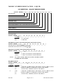
MODEL NUMBER DESIGNATION - LIQUID
HP INSERTION - LIQUID TURBINE SERIES
MODEL HP-B-( A )- ( B-C )-( D )-( E )-( F )-( G )-( H )-( I )-( J )-( K )
ROTOR SIZE
MINIMUM FLOW RATE IN
MAXIMUM FLOW RATE IN FPS
PROCESS CONNECTION/END FITTING
BEARING TYPE
PICKUP COILS
EXPLOSION-PROOF COIL JUNCTION ENCLOSURES
BI-DIRECTIONAL FLOW
STEM LENGTH
ADJUSTABLE OR FIXED STEM
SPECIAL FEATURES
ROTOR SIZE
MODEL HP-B-( A )- ( - )-( )-( )-(
OPTION ( A )
(11/2")
11/2" ROTOR
(2")
2" ROTOR
)-(
)-(
)-(
)-(
)-(
MINIMUM FLOW AND MAXIMUM FLOW RATE IN FPS
MODEL HP-B-( )- ( B - C )-( )-( )-( )-( )-( )-( )-(
MINIMUM FLOW RATE IN FPS ( B - )
MAXIMUM FLOW RATE IN FPS ( - C )
)-(
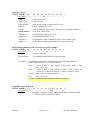
PROCESS CONNECTION/END FITTING TYPE
MODEL HP-B-( )-( - )-( D )-( )-( )-( )-( )-( )-( )-(
OPTION ( D )
(2NPT)
2" MALE NATIONAL PIPE THREAD
(3NPT)
3" MALE NATIONAL PIPE THREAD
NOTE:
)
)
)
ALL S/S FLANGES ARE 316L S/S DUAL RATED UNLESS
OTHERWISE SPECIFIED.
BEARING TYPE
MODEL HP-B-( )-( - )-( )-( E )-( )-( )-( )-( )-( )-( )
TURBINE
SIZES OPTION ( E )
11/2"
(CB)
CERAMIC HYBRID BALL BEARING, SELF LUBRICATING
(C)
HARD CARBON COMPOSITE SLEEVE BEARING
(T)
TUNGSTEN CARBIDE SLEEVE BEARING
2"
HP-208
(CB)
(C)
(T)
CERAMIC HYBRID BALL BEARING, SELF LUBRICATING
HARD CARBON COMPOSITE SLEEVE BEARING
TUNGSTEN CARBIDE SLEEVE BEARING
Page 2 of 17
HP Insertion Meter
PICKUP COILS
MODEL HP-B-( )-( OPTION ( F )
)-(
)-(
)-( F )-(
)-(
)-(
)-(
)-(
)
(1M)
ONE MAG COIL
(1MC3PA)
ONE RF COIL
(1MC2PAHT)
ONE HIGH TEMP 6" PIGTAIL RF COIL
(1HTM)
HIGH TEMP MAG COIL
(1ISM)
(1ISM-ATEX)
ONE INTRINSICALLY SAFE MAG COIL, NORTH AMERICA
ONE ISM ATEX COIL
(1RPMXXX)
ONE REDI-PULSE MAG COIL
(1RPRXXX)
ONE REDI-PULSE RF COIL
(1DMXXXX)
ONE REDI-PULSE INTRINSICALLY SAFE MAG COIL
(1DRXXXX)
ONE REDI-PULSE INTRINSICALLY SAFE RF COIL
EXPLOSION-PROOF COIL JUNCTION ENCLOSURES
MODEL HP-B-( )-( - )-( )-( )-( )-( G )-( )-( )-( )-(
OPTION ( G )
(E2)
E2 ENCLOSURE
(X-ATEX)E2
)
3/4" MNPT RISER WITH E2 ENCLOSURE
E2 NOTES: EXPLOSION-PROOF/FLAME-PROOF ENCLOSURE WITH 3/4"
FNPT MOUNT AND 3/4" CABLE ENTRY
FM:
CSA:
CLASS I, DIV. 1, GR. ABCD, CLASS II/III, DIV. 1, GR.
EFG, TYPE 4X
CLASS I, DIV. 1, GR. ABCD, CLASS II, DIV 1, GR. EFG,
CLASS III, TYPE 4X, EX D IIC, CLASS I, ZONE 1, IP 66
ATEX:
EX II 2GD Ex d tD IIC, IP66/68
IEC:
EX D IIC IP68
FOR UL LISTED ENCLOSURE CONTACT FACTORY
BI-DIRECTIONAL FLOW
MODEL HP-B-( )- ( - )-( )-( )-( )-( )-( H )-( )-( )-( )
OPTION ( H )
(BF)
BI-DIRECTIONAL FLOW. REQUIRES THE 2" ROTOR AND
3" END FITTING OPTIONS ABOVE.
HP-208
Page 3 of 17
HP Insertion Meter
STEM LENGTH
MODEL HP-B-( )-( - )-( )-( )-( )-(
OPTION ( I )
INSERT INCHES REQUIRED
)-(
)-( I )-(
)-(
)
ADJUSTABLE OR FIXED STEM
MODEL HP-B-( )-( - )-( )-( )-( )-( )-( )-( )-( J )-( )
OPTION ( J )
(AL)
ADJUSTABLE (LOW PRESSURE 150# MAX)
(AH)
ADJUSTABLE (HIGH PRESSURE, DEPENDENT UPON
(F)
FIXED
SPECIAL FEATURES
MODEL HP-B-( )-( - )-( )-( )-( )-( )-( )-( )-( )-( K )
OPTION ( K )
(CE)
CE MARK REQUIRED FOR EUROPE
THE HOUSING TO MEET PED REQUIREMENTS.
HP-208
(SEP-CE)
SOUND ENGINEERING PRACTICE
(SP)
ANY FEATURES THAT ARE NOT COVERED IN THE
MODEL NUMBER, USE A WRITTEN DESCRIPTION OF
THE -SP.
Page 4 of 17
HP Insertion Meter
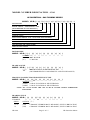
MODEL NUMBER DESIGNATION - GAS
HP INSERTION - GAS TURBINE SERIES
MODEL HP-B-( A )- ( B )-( C )-( D )-( E )-( F )-( G )-( H )-( I )-( J )
ROTOR SIZE
BLADE ANGLE - ASSIGNED BY TPC
(DETERMINED BY GAS DENSITY)
PROCESS CONNECTION/END FITTING
BEARING TYPE
PICKUP COILS
EXPLOSION-PROOF COIL JUNCTION ENCLOSURES
BI-DIRECTIONAL FLOW
STEM LENGTH
ADJUSTABLE OR FIXED STEM
SPECIAL FEATURES
ROTOR SIZE
MODEL HP-B-( A )- ( )-( )-( )-(
OPTION ( A )
(11/2") 11/2" ROTOR
(2")
2" ROTOR
)-(
)-(
)-(
)-(
)-(
)
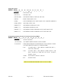
BLADE ANGLE
MODEL HP-B-( )- ( B )-( )-( )-( )-( )-( )-( )-( )-( )
BLADE ANGLE, ASSIGNED BY TPC
(B)
(DETERMINED BY GAS DENSITY AND FLOW RANGE)
PROCESS CONNECTION/END FITTING TYPE
MODEL HP-B-( )-( )-( C )-( )-( )-( )-( )-( )-( )-(
OPTION ( C )
(2NPT) 2" MALE NATIONAL PIPE THREAD
(3NPT) 3" MALE NATIONAL PIPE THREAD
)
NOTE: ALL S/S FLANGES ARE 316L S/S DUAL RATED UNLESS OTHERWISE
SPECIFIED.
BEARING TYPE
MODEL HP-B-( )-( )-( )-( D )-(
TURBINE
OPTION ( D )
SIZES
)-(
)-(
)-(
)-(
)-(
)
11/2"
(CB)
CERAMIC HYBRID BALL BEARING, SELF LUBRICATING
2"
(CB)
CERAMIC HYBRID BALL BEARING, SELF LUBRICATING
HP-208
Page 5 of 17
HP Insertion Meter
PICKUP COILS
MODEL HP-B-( )-( )-( )-( )-( E )-( )-(
OPTION ( E )
(1M)
ONE MAG COIL
)-(
)-(
)-(
)
(1MC3PA)
ONE RF COIL
(1MC2PAHT)
ONE HIGH TEMP 6" PIGTAIL RF COIL
(1HTM)
HIGH TEMP MAG COIL
(1ISM)
ONE INTRINSICALLY SAFE MAG COIL, NORTH AMERICA
(1ISM-ATEX)
ONE ISM ATEX COIL
(1RPMXXX)
ONE REDI-PULSE MAG COIL
(1RPRXXX)
ONE REDI-PULSE RF COIL
(1DMXXXX)
ONE REDI-PULSE INTRINSICALLY SAFE MAG COIL
(1DRXXXX)
ONE REDI-PULSE INTRINSICALLY SAFE RF COIL
EXPLOSION-PROOF COIL JUNCTION ENCLOSURES
MODEL HP-B-( )-( - )-( )-( )-( )-( F )-( )-( )-( )-(
OPTION ( F )
(E2)
E2 ENCLOSURE
)
(X-ATEX)E2
3/4" MNPT RISER WITH E2 ENCLOSURE
E2 NOTES:
EXPLOSION-PROOF/FLAME-PROOF ENCLOSURE WITH
3/4" FNPT MOUNT AND 3/4" CABLE ENTRY
FM:
CLASS I, DIV. 1, GR. ABCD, CLASS II/III, DIV. 1,
CSA:
CLASS I, DIV. 1, GR. ABCD, CLASS II, DIV 1, GR.
GR. EFG, TYPE 4X
EFG, CLASS III, TYPE 4X, EX D IIC, CLASS I,
ZONE 1, IP 66
ATEX:
EX II 2GD Ex d tD IIC, IP66/68
IEC:
EX D IIC IP68
FOR UL LISTED ENCLOSURE CONTACT FACTORY
HP-208
Page 6 of 17
HP Insertion Meter
BI-DIRECTIONAL FLOW
MODEL HP-B-( )- ( )-(
)-(
)-(
)-(
)-( G )-(
)-(
)-(
)
OPTION ( G )
(BF)
BI-DIRECTIONAL FLOW. REQUIRES THE 2" ROTOR
AND 3" END FITTING OPTIONS ABOVE.
STEM LENGTH
MODEL HP-B-(
)-(
)-(
)-(
)-(
)-(
)-(
)-( H )-(
)-(
)
OPTION ( H )
INSERT INCHES REQUIRED
ADJUSTABLE OR FIXED STEM
MODEL HP-B-( )-( )-( )-( )-(
)-(
)-(
)-( )-( I )-(
)
OPTION ( I )
(AL)
(AH)
ADJUSTABLE (LOW PRESSURE 150# MAX)
ADJUSTABLE (HIGH PRESSURE, DEPENDENT UPON
(F)
FIXED
SPECIAL FEATURES
MODEL HP-B-( )-( )-( )-( )-( )-( )-( )-( )-( )-( J )
OPTION ( J )
(CE)
CE MARK REQUIRED FOR EUROPE
AND TEMPERATURE MUST BE KNOWN AND ENTERED
ON THE ORDER. THIS INFORMATION WILL BE MARKED
ON THE HOUSING TO MEET PED REQUIREMENTS.
(SEP-CE)
SOUND ENGINEERING PRACTICE
(SP)
ANY FEATURES THAT ARE NOT COVERED IN THE MODEL
NUMBER, USE A WRITTEN DESCRIPTION OF THE -SP.
HP-208
Page 7 of 17
HP Insertion Meter
PRINCIPLE OF OPERATION
The HP Series Profile/Insertion Flowmeter is a velocity measuring, turbine type
flowmeter.
The flowing fluid engages the vaned rotor causing it to rotate at an angular
velocity proportional to the fluid flow rate.
The angular velocity of the rotor results in the generation of an electrical signal
(AC sine wave type). Summation of the pulsing electrical signals relates directly
to the total flow. The frequency of the signal relates directly to the flow rate.
The vaned rotor is the only moving part of the flowmeter.
ELECTRICAL DESCRIPTION
The pickup coil furnished with the flowmeter is a sensing device that converts the
motion of the rotating rotor into essentially an AC sine wave.
Pickup Coil - The variable reluctance pickup contains a permanent magnet and
associated wire-wound coil and the modulated carrier pickup contains an
oscillator and associated wire-wound coil. For both coil types the movement of
the of the rotor blade across the coil tip produces an AC signal within the coil
winding.
Pickup Coil Output - As described above is transmitted by the shielded cable to
the electronic instrumentation for proper factoring, display, and control.
HP SERIES SPECIFICATION
Materials:
Stem, Housing, Rotor Support – 304 stainless.
Bearing – 440SS shielded ball bearings, hard carbon composite,
tungsten carbide sleeve.
Rotor – 17.4 stainless (Standard), Nickel 200, 430 stainless.
Seals – Rulon (Standard), Viton, Teflon.
End Fittings:
Flanged and NPT threaded are available.
Electrical:
Connections – Terminal block in conduit enclosure. Flying leads for
preamp or two-wire transmitter.
Pickup – Variable reluctance type, nominal DC resistance 1300 ohms
(standard). Minimum output level 10 millivolt RMS.
– Modulated Carrier type, nominal DC resistance 11.5 ohms.
Frequency Range – 0 to 500 Hz.
HP-208
Page 8 of 17
HP Insertion Meter
INSTALLATION
In choosing the location to mount the insertion meter it is recommended that
there be 10 to 20 pipe diameters upstream and 5 to 10 diameters downstream.
This will allow the highest measuring accuracy while tending to minimize
swirl.*
Care should be exercised not to locate the HP Series Flowmeter in close
proximity to electronically noisy devices which could introduce stray noise
into the pickup coil. In running the signal cable from the HP Series Flowmeter
to the associated electronics, care should be taken in the choice of layout so as
not to introduce noise or crosstalk with other cabling. It is advisable not to run
the signal cable within a conduit with power lines. Shielded cabling is required
and should be terminated as specified in the manual for the electronic
measurement system.
See the installation drawings for a typical installation. Make sure the riser,
valve, and HP Series Flowmeter have pressure ratings suitable for the desired
service conditions before installation begins. Also, check materials
compatibility if the fluid is corrosive.
The HP Series Profile/Insertion Flowmeter is designed to be mounted on a full
port valve which is in turn mounted on a riser welded to the pipeline.
The HP Series Flowmeter may be mounted into an active line using
conventional hot tap techniques. This allows for the installation of the meter
without an interruption of service.
Weld a short riser with appropriate pressure rating to the pipeline. This riser
and the full port valve should have the mating fitting required by the HP Series
Flowmeter. Correct gaskets and bolt types should be utilized.
At this point, a hot tap device is mounted on the valve and a hole made through
the pipe wall. The hot tap device is retracted and the valve is closed.
Mount the HP Series Flowmeter to the isolating valve.
Open the full port valve to its fully open position. Insert the HP Series
Flowmeter to the desired insertion depth. The stem is graduated to aid in
positioning to the desired depth.
*
NOTE: A swirl present in the fluid ahead of the meter can change
the effective angle of engagement and, therefore, cause a
deviation from the supplied calibration. Proper installation
of the flowmeter minimizes the harmful effects of fluid
swirl.
HP-208
Page 9 of 17
HP Insertion Meter
Aligning the handle with the center line of the pipe will also align the turbine
rotor to the proper position. The turbine rotor is normally calibrated in one
direction. The handle is marked with the calibrated direction of flow. A rotor
may be calibrated in both directions where required. In the later application the
arrow indicates the flow direction for the 'forward' calibration.
In order for the HP Series Flowmeter to properly measure fluid flow, it is
necessary to insert the well assembly at the mean velocity point. At this depth,
the velocity and net area of the pipe section may be used to calculate the pulses
per unit-volume of the measuring section. The mean velocity point is a weak
function of flow rate, as well as other factors which influence Reynolds
number.
The mean velocity point may be determined using experimental methods to
establish the flow profile and empirically determine the desired insertion depth
(See Table C).
Table C includes the approximate location of the mean velocity point in large
diameter pipes. For small diameter piping, locate the rotor in the center of the
pipe to eliminate sidewall effects near the pipe wall. Due to profile effects, a
scaling factor must be used with center positioning.
It should be noted that the turbine rotor responds to the average velocity
appearing across its surface. While the mean velocity depth may vary, it will
often remain within the diameter of the turbine rotor and thereby minimize the
affects of not being exactly at the mean velocity depth.
STRAINERS/FILTERS
Profile/Insertion flowmeters are designed for use in a clean fluid service.
However, the service fluid may carry some particulate material which would
need to be removed before reaching the flowmeter. Under these conditions a
strainer/filter may be required to reduce the potential hazard of fouling or
damage that may be caused by foreign matter. Strainer/filters are recommended
to be used with the Hoffer Mini-Flow Series meters.
METER SIZE
MESH SIZE
MF Series
¼” to ½”
5
/8” to 1¼”
1½” to 3”
4” to 12”
100
100
70
40
24
PARTICLE SIZE
(Maximum)
.0055
.0055
.008
.015
.028
If a strainer/filter is required in the system, it should be located upstream of the
flowmeter taking care that the proper minimum distance is kept between the
strainer and flowmeter.
HP-208
Page 10 of 17
HP Insertion Meter
MAINTENANCE
The field maintenance of the HP Series Flowmeter is limited to inspection
and/or replacement of a few components.
In general, it is advisable to remove the insertion meter from the line on a
periodic basis and examine it for contamination and wear.
Contamination of the rotor may occur if foreign matter succeeds in wrapping
itself about the well assembly. This is easily removed. The turbine rotor should
be checked for obvious damage (i.e., bent blades, shaft, etc.). If no damage is
apparent and the rotor spins freely, it may be returned into service.
The types of bearings installed in the flowmeter have been selected to operate
in the type of service being metered.
It is recommended that the bearings be checked periodically for wear. Since the
type of fluid being measured, as well as temperature, have a direct relationship
on the bearing life expectancy, it is best to contact the HFC Engineering
Department for the proper preventive maintenance interval.
If the rotor wobbles on the shaft, bearing wear is indicated and necessitates
replacement. If the rotor fails to spin freely, the bearings may be suspected.
Ball bearings may be replaced in the field, all others should be returned to
factory for rework and recalibration.
It is recommended that the bearings be replaced if any signs of wear are
apparent. An unexplained shift in the output accuracy could be a sign of worn
bearings.
CAUTION:
If bearings are allowed to operate without replacement at
the recommended interval, the accuracy of the device may
drift from the original calibration and if left long enough
severe damage to the rotor may occur.
Should the unit fail to produce an output signal while the rotor is spinning, the
pickup coil may be suspect.
Complete calibrated Well Assemblies are available from Hoffer Flow Controls,
Inc. Consult factory for pricing and availability.
BALL BEARING REPLACEMENT
Remove the meter to a clean, flat work surface.
To disassemble:
Loosen the stem clamp and carefully slide the housing towards the handle
exposing the Well Assembly (coil and rotor housing).
Inspect the rotor and Well for damage (bent blades, bent/damaged Well
supports, etc.). All damaged parts must be replaced.
HP-208
Page 11 of 17
HP Insertion Meter
Using a ¼” (for 1½” meter) or 5/16” (for 2” meter) Spintite, remove one
shaft locknut.
Carefully slide the shaft out while supporting the rotor. The rotor will
drop out once the shaft is removed.
Remove the deflector cones, one from each side of the Well supports.
Carefully inspect all components, replace any that may be worn or
damaged.
To reassemble:
Install the deflector cones into the Well supports (one in each side).
Insert new ball bearings and shaft bushing into the rotor.
Position the rotor between the cones, making sure that the “In” side of the
rotor faces into the direction of flow. Flow direction is marked on the
bottom of the Well Assembly.
Install shaft.
Install shaft locknut.
Check that the rotor spins freely.
Carefully slide the housing over the Well Assembly to the “Fully
Retracted” position, as marked on the stem, and tighten the clamp.
PICKUP COIL REPLACEMENT
Remove the meter to a clean, flat work surface.
To disassemble:
Disconnect the coil wires in the conduit enclosure.
Loosen the stem clamp and carefully slide the housing towards the handle
exposing the Well Assembly.
Carefully unscrew and remove the Well Assembly from the stem, pulling
the pickup coil wires from the stem.
Unscrew and remove the pickup coil from the Well Assembly.
To reassemble:
Install the new pickup coil into the Well Assembly.
Replace the O-ring Well Assembly seal.
Route the pickup coil wires through the center of the stem to the conduit
enclosure.
Screw the Well Assembly on the stem tightening until the Well Assembly
is parallel with the handle. Make sure that the flow direction of the Well
Assembly is pointing in the same direction as the handle.
Carefully slide the housing over the Well Assembly to the “Fully
Retracted” position, as marked on the stem, and tighten the clamp.
Reconnect the coil wires in the conduit enclosure.
HP-208
Page 12 of 17
HP Insertion Meter
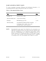
SPARE AND REPLACEMENT PARTS
To assure maximum operating efficiency and minimum downtime, it is
recommended that the spare parts listed in Table A be stocked.
Table A - Recommended Spare Parts
Part
Nomenclature
Qty.
Pickup Coil
Pickup Coil w/ leads
1
Well Assembly Seal
2-020 Viton O-Ring
1
Bearings
Ball Bearing type only
1 (set)
Well Assembly
Assembled & calibrated Well Assembly
consisting of rotor, shaft, cones, well
assembly frame, and O-ring seal
1
NOTE:
HP-208
Recommended spare parts lists should not be construed as an
indication of possible failure, but reflect material available only
from the manufacturer or his authorized representative. Spare
parts are recommended for a normal operating period of 18
months. Quantity of recommended spares is based upon a single
unit at any given location and provisioning may be adjusted
accordingly in the event that multiple units comprise a system.
Page 13 of 17
HP Insertion Meter
INSERTION DEPTH DETERMINATION
A review of the principles of fluid flow in pipelines reveals that the velocity of
the fluid across the pipe is not constant. Under a given set of conditions a flow
profile exists which varies from a parabolic shape in laminar flow to
approximately flat in the turbulent flow region.
It is the average flow in the pipeline which is of interest in obtaining a
measurement of flow in the pipe. For medium diameter pipes (diameters of 10
inches and less) the turbine is positioned at the center of the pipe. Center line
positioning is recommended to avoid the effects of stagnant flow near the pipe
wall and the turbulence of fluid near the riser. For large diameter pipes
(diameters greater than 10 inches), the turbine is positioned at the depth where
the flow equals the average fluid velocity of the flow.
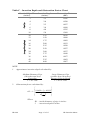
Table C lists the required insertion depth for selected pipe diameters.
CALIBRATION CONSTANTS DETERMINATION
Calibration of the metering section consists of relating the precise velocity
measurement at the specified insertion depth to the geometry of the piping to
obtain a measurement of the entire flow through the metering section.
Calculate the calibration constant for the metering section (KMS) using the
following equation:
K
K MS
PFAVE
FMS
KMS
60
ID
OF
24
2
(Pulses / FT3 )
(Hz / FT3 / Min)
where
K - K FACTOR from calibration sheet (Hz/FPS)
PF - Mean Profile Scaling Factor (equal to 1 for large diameter
pipes)
OF - Obstruction Factor
ID - Inner diameter of pipe (inches)
HP-208
Page 14 of 17
HP Insertion Meter
A consequence of using center line positioning in medium diameter pipes is
that a scaling factor, relating the average flow to the center line flow, must be
included in determining the calibration constant of the metering section. In
general, the profile scaling factor (PF) relates to the shape of the velocity
profile under a given set of fluid conditions (i.e., Reynolds Number (Rn)). In
large diameter pipes the profile scaling factor (PF) is equal to one since the
turbine is located at the average velocity point.
It is necessary to consider the effects of the flow profile (PF) within the line as
well as the obstruction that the stem and well assembly present to the fluid flow
(OF).
The profile scaling factor may be obtained from measured data or by utilizing
empirical equations derived from fluid mechanics of the fluid profile shape as a
function of Reynolds Number.
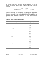
Table B lists the profile scaling factor derived from one such empirical
equation. To choose the correct profile scaling factor, determine the Reynolds
Number corresponding to the anticipated minimum and maximum flow rates
using the following equation:
for Liquid Service:
Rn
for Gas Service:
3160 Q
ID
Rn
where
Q - flow in US gallons
per minute
ID - pipe bore in inches
- viscosity in Centistokes µ
where
Q D ID -
QD4
ID
flow rate in SCF/sec
density in #/ft3
nominal pipe ID in inches
viscosity of gas in
#/in-sec
From Table B obtain the profile scaling factors corresponding to the
approximate Reynolds Number.
Calculate the mean profile scaling factor using the following equation:
PFAVE
HP-208
PFMAX PFMIN
2
Page 15 of 17
HP Insertion Meter
An estimate of the error introduced into the indicated flow by the
varying flow profile may be made with the aid of the following
equation:
% ERROR
P F
M A X P F M IN
2 P F AVE
100%
It may be noted that the percent error will increase as a larger turn
down range is sought. It is therefore advisable that PFMAX and PFMIN be
chosen to correspond to the actual conditions expected and not on the
maximum and minimum capabilities of the Profile/Insertion
Flowmeter.
Table B - Profile Scaling Factor Chart
Reynolds Number (Rn)
Profile Scaling Factor (PF)
4 x 10³
.791
6
.796
8
.797
4
1 x 10
.800
2
.806
4
.811
6
.813
8
.816
5
1 x 10
.818
2
.827
4
.837
6
.841
8
.847
6
HP-208
1 x 10
.849
2
.865
4
.865
Page 16 of 17
HP Insertion Meter
Table C – Insertion Depth and Obstruction Factor Chart
Nominal Pipe ID
(inches)
Insertion Depth
(inches)
Obstruction Factor
(OF)
3
1.5
.8245
4
2.0
.8590
5
2.5
.8827
6
3.0
.8998
8
4.0
.9225
10
5.0
.9369
10
1.25
.9876
12
1.50
.9890
14
1.75
.9902
16
2.00
.9912
18
2.25
.9920
20
2.50
.9927
24
3.00
.9937
30
3.75
.9949
36
4.50
.9957
42
5.25
.9962
48
6.00
.9967
NOTE:
1.
Approximate insertion depth calculated by:
Medium Diameter Pipe
(10 inches and less)
Centerline
e
I = 0.5 x ID
2.
Large Diameter Pipe
(greater than 10 inches)
Average Velocity Depth
I = 0.125 x ID
Obstruction factor calculated by:
I
.
.
10625
0
3535
OF 1
2
ID
2
Where
ID - inside diameter of pipe in inches
I - insertion depth in inches
HP-208
Page 17 of 17
HP Insertion Meter