1
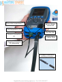
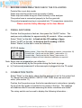
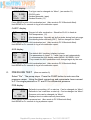
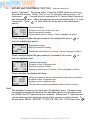
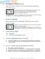
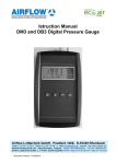
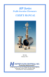
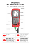
KANE455
QUICK REFERENCE GUIDE
Infra-red emitter and torch light
Menu controls ~
Scroll up/down
Enter
Function buttons x 4
(See below for details)
Rotary switch
Particle filter
Water trap
“Battery charging” indicator
Analyser Connections
(see diagram overleaf)
ON / OFF
Turns the analyser ON / OFF
Flue Gas Inlet
(see diagram overleaf)
PUMP
Turns the pump ON / OFF
Hold button to zero pressure
SEND / ENTER
BACKLIGHT
Switches backlight & torch light
ON / OFF
Send readings to printer
(Press button for 1 second.)
Send readings to memory
(Hold button down for 2+ secs.)
Stock No: 18839
Supplied By www.heating spares.co Tel. 0161 620 6677
Flue probe temperature (T1)
Battery charger
connection
Inlet temperature (T2)
Flue Gas Inlet
Pressure connection
P1
Rubber Bung
Pressure connection
P2 (differential)
Fit Spigot to Hose before
connecting to Analyser
Supplied By www.heating spares.co Tel. 0161 620 6677
1.
BEFORE USING ANALYSER CHECK THE FOLLOWING:
Particle filter is not dirty inside
Water trap and flue probe hose are empty of water
Water trap and rubber bung are fitted correctly to the analyser
Flue probe hose is connected properly to the flue gas inlet
Flue probe temperature plug is connected into T1 temperature connection
Please read the Safety Warnings in the User Manual
2.
FRESH AIR PURGE
Position the flue probe in fresh air, then press the “On/Off” button. The
analyser auto-calibrates for approximately 90 seconds. When complete…
Select “Ratio” on the dial. In fresh air the CO reading = 0ppm
Select “O2/Eff” on the dial. In fresh air the O2 reading = 20.9%
Select “Status” on the dial to view the following…
STATUS display
BAT
59
11 : 46 : 29
15 / 05 / 08
CAL
283
- Battery status. If less than 20 recharge or replace, (see section 10)
- Current time. Can be set via the “Menu”, (see section 11)
- Current date. Can be set via the “Menu”, (see section 11)
- Number of days until next check and calibration is required
Note: Boiler inlet air temperature can either be…
a) Set automatically by the flue probe during the fresh air purge
or b) Continuously measured if a thermocouple is plugged into the T2 socket
3.
COMBUSTION TESTS
Select “Ratio” on the dial to check that the analyser is set for the correct fuel.
To change fuel select MENU / SETUP / SET FUEL then use scroll and
enter, (see section 11).
Position the flue probe as per the boiler manufacturer’s instructions; typically
the tip of the flue probe is inserted to the centre of the flue. The readings
will stabilise after 60 seconds assuming the boiler conditions are stable.
The rotary switch can be used to display the following information…
Supplied By www.heating spares.co Tel. 0161 620 6677
RATIO display
NAT GAS
R
0.0001
COP
12
CO2% 8.8
- Fuel type can be changed via “Menu”, (see section 11)
- CO/CO2 ratio
- Carbon Monoxide, (ppm)
- Carbon Dioxide, (%)
Press SEND to print a full combustion test. (Also sends to PC if Bluetooth fitted).
Hold SEND for 2+ seconds to log a full combustion report.
O2/EFF display
O2%
TFC
TIC
EfC%
5.4
55.1
17.2
98.3
- Oxygen left after combustion. Should be 20.9% in fresh air.
- Flue temperature, (°C)
- Inlet temperature. Normally set by flue probe during fresh air purge.
- Condensing boiler efficiency (EfC). Can be changed via “Menu”
Press SEND to print a full combustion test. (Also sends to PC if Bluetooth fitted).
Hold SEND for 2+ seconds to log a full combustion report.
AUX display
O2%
20.9 - The default AUX (auxiliary) display is shown
The parameters on lines 1, 2, 3 and 4 can be set independently
COP
00
To customise the AUX display select MENU / SCREEN / AUX.
11 : 55 : 02
They remain the AUX parameters until changed again by the user.
BAT
59
Press SEND to print a full combustion test. (Also sends to PC if Bluetooth fitted).
Hold SEND for 2+ seconds to log a full combustion report.
4.
PRESSURE TEST
(Also see section 9)
Select “Prs”. The pump stops. Press the PUMP button to auto-zero the
pressure sensor. Using the black connectors and manometer hose connect
to P1 for single pressure or P1 and P2 for differential pressure.
PRS display
PRESSURE
P
-0.04
mbar
12 : 56 : 29
- Defaults to smoothing ‘off’ on start-up. Can be changed via “Menu”.
- Defaults to ‘low’ resolution on start-up. Can be changed via “Menu”.
- Pressure units can be changed via “Menu”.
- Displays time to enable manually timed tests.
Press SEND to print a pressure test. (Also sends to PC if Bluetooth fitted).
Hold SEND for 2+ seconds to log a pressure report.
Supplied By www.heating spares.co Tel. 0161 620 6677
5.
LET-BY and TIGHTNESS TESTING
(Also see section 9)
Select “Tightness”. The pump stops. Press the PUMP button to auto-zero
the pressure sensor. Select “yes” or “no” for the let-by test by using
or ,
then press
. Connect from the test point to P1 using a black connector
and manometer hose. Adjust the gas pressure as you would with a “U” tube
manometer. Press
to start either the let-by test or the stabilisation
period…
LET BY
P1
10.35
P2
10.35
TIME
59
- Let-by test display.
- Pressure at the start of the let-by test
- Real time pressure reading
- Let-by default time is 1 minute. Can be changed via “Menu”.
When complete adjust the gas pressure if necessary then press
start the stabilisation period…
to
- Stabilisation display.
STABIL’N
P1
20.00 - Real time pressure reading
mbar
TIME
59 - Stabilisation default time is 1 minute. Can be changed via “Menu”.
When complete adjust the gas pressure if necessary then press
start the tightness test…
TIGHTN’S
P1
20.33
P2
20.33
TIME
119
to
- Tightness test display.
- Pressure at start of tightness test
- Real time pressure reading
- Tightness default time is 2 minute. Can be changed via “Menu”.
When complete the display will show…
LOG
06
P1
20.33
P2
20.26
PRINT
- Let-by and tightness test are automatically stored as a log number
- Pressure at start of tightness test
- Pressure at end of tightness test
- The test can be printed immediately or later from the memory
Note:
The analyser’s memory can store up to 20 tightness tests. Tightness tests
are logged automatically therefore the tightness section of the memory will
be full after the 20th tightness test is complete. Before the 21st tightness test
can be performed the tightness section of the memory must be cleared. To
do this select MENU / REPORT / TIGHTN’S / DEL ALL / YES then press
Supplied By www.heating spares.co Tel. 0161 620 6677
6.
DIFFERENTIAL TEMPERATURE
Select “Diff Temp” to measure flow, return and differential temperatures
DIFF TEMP display
TEMP
T1C
60.1
T2C
47.0
TC
13.1
- Pump automatically switches off when dial is moved to Diff Temp
- Use the T1 connection for the flow temperature sensor
- Use the T2 connection for the return temperature sensor
- Real time temperature difference
Press SEND to print a differential temperature test. (Also sends to PC if Bluetooth fitted).
Hold SEND for 2+ seconds to log a differential temperature report.
7.
ROOM CO TESTING
Select “Room CO” for CO investigations. Please refer to user manual.
ROOM CO display
ROOM
COP
TEST
LOG
8.
CO
00
14
01
- Duration of this test is variable from 0 to 30 minutes as per BS7967
- Real time CO reading, (ppm)
- Test 00 = start. To stop the Room CO test press the PUMP button
- The complete Room CO test is automatically stored as a log number
OTHER DISPLAY CODES
-PO- = Pump Off
-OC- = Open Circuit on temperature input
9.
FOR BEST PRESSURE SENSOR ACCURACY
1)
2)
10.
Switch the analyser on for 5 minutes to let the temperature stabilise.
Zero the pressure sensor when the analyser in the exact position that
it will be used.
TO FULLY CHARGE NiMH RECHARGEABLE BATTERIES
1)
2)
3)
4)
The analyser must be switched on.
Connect the charger and switched it on; charging indicator illuminates.
Switch the analyser off; the display will show “BATTERY CHARGING”.
The BAT status number of fully charged NiMH batteries is typically 70+
Supplied By www.heating spares.co Tel. 0161 620 6677
11.
USING THE MENU
Select “Menu” on the rotary switch and navigate using the function buttons…
= Scroll up
= Scroll down
= Enter
MAIN MENU
SUB MENU
OPTIONS / COMMENTS
SETUP
SET FUEL
NAT GAS, L OIL (28/35 sec), PROPANE, BUTANE, LPG, PELLETS
(Wood)
N
EfN = nett efficiency, EfG = gross efficiency, EfC = condensing efficiency
PRESSURE
REPORT
SCREEN
SERVICE
C
G
SET TIME
Uses Military time. 7am = 07:00, 7pm = 19:00
SET DATE
Uses DD-MM-YY format
SMOOTH
OFF = normal response. ON = slower (damped) response
RESOLVE
LOW = normal. HIGH = displays to an extra decimal place
PS UNITS
mbar, mmH2O, Pa, kPa, PSI, mmHg, hPa, InH2O
TIMES
LET-BY = Set duration of let-by test in minutes. Default = 1 minute
STABIL’N = Set duration of stabilisation in minutes. Default = 1 minute
TIGHTN’S = Set duration of tightness test in minutes. Default = 2 minute
COMB’N
Stored combustion tests, VIEW, DEL ALL or EXIT
(max = 99 tests)
PRESSURE
Stored pressure tests, VIEW, DEL ALL or EXIT
(max = 20 tests)
TIGHTN’S
Stored let-by and tightness tests, VIEW, DEL ALL or EXIT,
(20 tests)
TEMP
Stored differential temperature tests, VIEW, DEL ALL or EXIT
(20 tests)
ROOM CO
Stored room CO tests, VIEW, DEL ALL or EXIT
CONTRAST
Factory setting is 04
AUX
Enables users to customise the parameters on the AUX display
User can set any parameter on lines 1, 2, 3 and 4
HEADER
Sets printout header, 2 lines, 20 characters per line
CODE
Password protected for authorised service agents. Leave set to 0000.
(max = 20 tests)
To EXIT EACH Sub MENU select EXIT.
To EXIT the MENU move the rotary switch to any position other than “Menu”.
Any changes that have not been “entered” will be ignored.
Supplied By www.heating spares.co Tel. 0161 620 6677
12.
Printouts
Supplied By www.heating spares.co Tel. 0161 620 6677