1
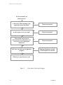
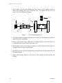
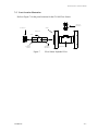
SY-100
FUEL FLOW SENSOR
USER’S MANUAL
Description, Operation, Installation
And
Maintenance Instructions
HP-214
March 1998
SY100 Flowmeter Technical Manual
Notice
HOFFER FLOW CONTROLS, INC. MAKES NO WARRANTY OF ANY KIND
WITH REGARD TO THIS MATERIAL, INCLUDING, BUT NOT LIMITED TO,
THE IMPLIED WARRANTIES OF MERCHANTABILITY AND FITNESS FOR A
PARTICULAR PURPOSE.
This manual has been provided as an aid in installing, connecting, calibrating, operating, and
servicing this unit. Every precaution for accuracy has been taken in the preparation of this
manual; however, HOFFER FLOW CONTROLS, INC. neither assumes responsibility for any
omissions or errors that may appear nor assumes liability for any damages that may result from
the use of the products in accordance with information contained in the manual.
HOFFER FLOW CONTROLS' policy is to provide a user manual for each item supplied.
Therefore, all applicable user manuals should be examined before attempting to install or otherwise
connect a number of related subsystems.
During installation, care must be taken to select the correct interconnecting wiring drawing. The
choice of an incorrect connection drawing may result in damage to the system and/or one of the
components.
Please review the complete model number of each item to be connected and locate the appropriate
manual(s) and/or drawing(s). Identify all model numbers exactly before making any connections.
A number of options and accessories may be added to the main instrument, which are not shown
on the basic user wiring. Consult the appropriate option or accessory user manual before
connecting it to the system. In many cases, a system wiring drawing is available and may be
requested from HOFFER FLOW CONTROLS.
This document contains proprietary information, which is protected by copyright. All rights are
reserved. No part of this document may be photocopied, reproduced, or translated to another
language without the prior written consent of HOFFER FLOW CONTROLS, INC.
HOFFER FLOW CONTROLS’ policy is to make running changes, not model changes,
whenever an improvement is possible. This affords our customers the latest in technology and
engineering. The information contained in this document is subject to change without notice.
RETURN REQUESTS / INQUIRIES
Direct all warranty and repair requests/inquiries to the Hoffer Flow Controls Customer Service Department, telephone
number (252) 331-1997 or 1-800-628-4584. BEFORE RETURNING ANY PRODUCT(S) TO HOFFER FLOW
CONTROLS, PURCHASER MUST OBTAIN A RETURNED MATERIAL AUTHORIZATION (RMA) NUMBER FROM
HOFFER FLOW CONTROLS’ CUSTOMER SERVICE DEPARTMENT (IN ORDER TO AVOID PROCESSING
DELAYS). The assigned RMA number should then be marked on the outside of the return package and on any
correspondence.
FOR WARRANTY RETURNS, please have the
following information available BEFORE contacting
HOFFER FLOW CONTROLS:
1. P.O. number under which the product was
PURCHASED,
2. Model and serial number of the product under
warranty, and
3. Repair instructions and/or specific problems relative
to the product.
HFC 9708
FOR
REPAIRS
OR
NON-WARRANTY
consult
HOFFER
FLOW
CALIBRATIONS,
CONTROLS for current repair/calibration charges. Have
the following information available BEFORE contacting
HOFFER FLOW CONTROLS:
1. P.O. number to cover the COST of the
repair/calibration,
2. Model and serial number of the product, and
3. Repair instructions and/or specific problems relative
to the product.
LIMITED WARRANTY
HOFFER FLOW CONTROLS, INC. (“HFC”) warrants HFC’s products (“goods”) described in the specifications
incorporated in this manual to be free from defects in material and workmanship under normal use and service, but only
if such goods have been properly selected for the service intended, properly installed and properly operated and
maintained. This warranty shall extend for a period of (1) year from the date of delivery to the original purchaser (or
eighteen (18) months if the delivery to the original purchaser occurred outside the continental United States). This
warranty is extended only to the original purchaser (“Purchaser”). Purchaser’s sole and exclusive remedy is the repair
and/or replacement of nonconforming goods as provided in the following paragraphs.
In the event Purchaser believes the goods are defective, the goods must be returned to HFC, transportation prepaid by
Purchaser, within twelve (12) months after delivery of goods (or eighteen (18) months for goods delivered outside the
continental United States) for inspection by HFC. If HFC’s inspection determines that the workmanship or materials
are defective, the goods will be either repaired or replaced, at HFC’s sole determination, free of additional charge, and
the goods will be returned, transportation paid by HFC, using the lowest cost transportation available.
Prior to returning the goods to HFC, Purchaser must obtain a Returned Material Authorization (RMA) Number from
HFC’s Customer Service Department within 30 days after discovery of a purported breach of warranty, but no later than
the warranty period; otherwise, such claims shall be deemed waived. See the Return Requests/Inquiries Section of this
manual.
If HFC’s inspection reveals the goods are free of defects in material and workmanship or such inspection reveals the
goods were improperly used, improperly installed, and/or improperly selected for service intended, HFC will notify the
purchaser in writing and will deliver the goods back to purchaser upon (i) receipt of Purchaser’s written instructions
and (ii) the cost of transportation. If Purchaser does not respond within 30 days after notice from HFC, the goods will
be disposed of in HFC’s discretion.
HFC does not warrant these goods to meet the requirements of any safety code of any state, municipality, or any other
jurisdiction, and purchaser assumes all risk and liability whatsoever resulting from the use thereof, whether used singly
or in combination with other machines or apparatus.
This warranty shall not apply to any HFC goods or parts thereof, which have bee repaired outside HFC’s factory or
altered in any way, or have been subject to misuse, negligence, or accident, or have not been operated in accordance
with HFC’s printed instructions or have been operated under conditions more severe than, or otherwise exceeding, those
set forth in the specifications for such goods.
THIS WARRANTY IS EXPRESSLY IN LIEU OF ALL OTHER WARRANTIES, EXPRESSED OR IMPLIED,
INCLUDING ANY IMPLIED WARRANTLY OF MERCHANTABILITY OR FITNESS FOR A PARTICULAR
PURPOSE. HFC SHALL NOT BE LIABLE FOR ANY LOSS OR DAMAGE RESULTING, DIRECTLY OR INDIRECTLY,
FROM THE USE OF LOSS OF USE OF THE GOODS. WITHOUT LIMITING THE GENERALITY OF THE FOREGOING, THIS
EXCLUSION FROM LIABILITY EMBRACES THE PURCHASER’S EXPENSES FOR DOWNTIME, DAMAGES FOR WHICH
THE PURCHASER MAY BE LIABLE TO OTHER PERSONS, DAMAGES TO PROPERTY, AND INJURY TO OR DEATH OF
ANY PERSON. HFC NEITHER ASSUMES NOR AUTHORIZES ANY PERSON TO ASSUME FOR IT ANY OTHER
LIABILITY IN CONNECTION WITH THE SALE OR USE OF HFC’S GOODS, AND THERE ARE NO AGREEMENTS OR
WARRANTIES COLLATERAL TO OR AFFECTING THE AGREEMENT. PURCHASER’S SOLE AND EXCLUSIVE REMEDY
IS THE REPAIR AND/OR REPLACEMENT OF NONCONFORMING GOODS AS PROVIDED IN THE PRECEDING
PARAGRAPHS. HFC SHALL NOT BE LIABLE FOR ANY OTHER DAMAGES WHATSOEVER INCLUDING INDIRECT,
INCIDENTAL, OR CONSEQUENTIAL DAMAGES.
HFC 9708
SY100 Flowmeter Technical Manual
FORWARD
The manual contains the information required to install, operate, maintain, and repair a
SY-100 Fuel Flow Sensor.
The SY-100 Fuel Flow Sensor is intended to be used with the SY-100 Naval Fuel Flowmeter
System which is used to provide ships personnel with the ability to monitor fuel oil
consumption at selected points on the vessel.
The SY-100 Fuel Flow Sensor is of a fail-safe construction where a failure of the flow sensor
will not result in a blockage of fuel flow nor will a portion of the Flow Sensor come adrift.
This manual is organized to permit ease of use. Individual sections are provided to cover
General Information, Operation, Functional Description, Preventative Maintenance,
Troubleshooting, Installation, and Corrective Maintenance. A parts list section is also
provided. Illustrations are used to improve the clarity of the information presented.
2.00 HP214
SY100 Flowmeter Technical Manual
TABLE OF CONTENTS
SY-100 TECHNICAL MANUAL .........................................................................................1
TABLE OF CONTENTS ...................................................................................................... i
LIST OF FIGURES.............................................................................................................. ii
SAFETY SUMMARY ........................................................................................................ iii
1. GENERAL INFORMATION..........................................................................................1
1-1 Introduction ...................................................................................................................................... 1
1-2 Equipment Description.................................................................................................................... 1
1-3 Reference Data ................................................................................................................................. 1
2. FUNCTIONAL DESCRIPTION .....................................................................................3
2-1 Introduction ...................................................................................................................................... 3
2-2 Principle of Operation ..................................................................................................................... 3
3. INSTALLATION............................................................................................................5
3-1
3-2
3-3
3-4
3-5
3-6
Introduction ...................................................................................................................................... 5
Installation Drawings....................................................................................................................... 5
Flow Sensor Site Selection ............................................................................................................. 6
Unpacking and Packing................................................................................................................... 7
Flow Sensor Installation.................................................................................................................. 8
Installation Checkout....................................................................................................................... 9
4. PREVENTATIVE MAINTENANCE............................................................................11
4-1
4-2
4-3
4-4
4-5
Introduction .................................................................................................................................... 11
Flow Sensor Cleaning.................................................................................................................... 11
Flow Sensor Inspection ................................................................................................................. 13
Lubrication ..................................................................................................................................... 14
Flow Sensor Assembly.................................................................................................................. 14
5. TROUBLESHOOTING ................................................................................................15
5-1 Introduction .................................................................................................................................... 15
5-2 Flow Sensor Troubleshooting Procedures ................................................................................... 15
6. CORRECTIVE MAINTENANCE ................................................................................17
6-1
6-2
6-3
6-4
Introduction .................................................................................................................................... 17
Flow Sensor Removal.................................................................................................................... 17
Flow Sensor Cleaning.................................................................................................................... 17
Flow Sensor Reinstallation ........................................................................................................... 19
7. PARTS LIST.................................................................................................................21
7-1
7-2
7-3
7-4
7-5
Introduction .................................................................................................................................... 21
List of Attaching Hardware........................................................................................................... 21
Recommend Spare Parts................................................................................................................ 22
List of Manufacturers .................................................................................................................... 22
Parts Location Illustration............................................................................................................. 23
APPENDIX A...................................................................................................................A-1
SY100 Flow Sensor Specification Summary..................................................................................... A-1
SY100 Flow Sensor Outline Drawings w/ Specifications ................................................................ A-7
2.00 HP214
i
SY100 Flowmeter Technical Manual
LIST OF FIGURES
Figure 1
Figure 2
Figure 3
Figure 4
Figure 5
Figure 6
Figure 7
Flow Sensor Cut-away...........................................................................................3
Flow Sensor Installation Piping Requirements .......................................................5
Flow Sensor Disassembly ....................................................................................12
Inspection of Internals Kit....................................................................................13
Flow Sensor Fault Logic Diagram........................................................................16
Flow Sensor Disassembly ....................................................................................18
Flow Sensor Exploded View ................................................................................23
ii
2.00 HP214
SY100 Flowmeter Technical Manual
SAFETY SUMMARY
The SY-100 Fuel Flow Sensor is designed to satisfy the safety requirements for shipboard
use.
The safety precautions and warnings described here are to be observed at all times.
Additional precautionary messages appear throughout this manual.
There is a danger associated with fuel oil spillage which may accompany the removal of the
flow sensor from the fuel line for maintenance or repair. Drain fuel lines completely prior to
removing the flow sensor.
There is danger associated with fuel oil leakage which may accompany the improper
installation of the gaskets and/or improper tightening of the flange mounting bolts. Verify the
quality and alignment of the flange gaskets prior to installation. Securely tighten the flange
bolts during installation of the flow sensor.
The fuel flow sensor should be installed downstream of a flow strainer. Large particles
passing through the flow sensor may result in a change in calibration or damage to the flow
sensor.
2.00 HP214
iii
SY100 Flowmeter Technical Manual
2.00 HP214
SY100 Flowmeter Technical Manual
1. GENERAL INFORMATION
1-1
Introduction
The SY-100 Fuel Flow Sensor is part of a general purpose fuel oil flow metering system
for use on shipboard installations. The system provides a number of display indications of
fuel usage and has an auxiliary output for optional connection to remote data acquisition
system.
This technical manual provides descriptive data, operation, maintenance, installation
instructions and repair parts lists for the SY-100 Fuel Flow Sensor.
1-2
Equipment Description
The SY-100 Fuel Flow Sensor is a rugged turbine flowmeter that when used with an
appropriate electronics unit provides a rugged fuel flow measurement system.
The intended use of this flow sensor is to aid in providing accurate fuel measurements
associated with the operations of shipboard power and propulsion plant boilers.
The SY-100 Fuel Flow Sensor is capable of accurately sensing the flow of MIL-F16884G Marine Diesel Fuel and similar low viscosity fuels.
The flow sensor has a fail-safe construction and minimal pressure drop in the event of
fouling. This adds to the ease of installation for shipboard service. A meter fuel bypass
line is not required.
1-3
Reference Data
APPENDIX A details the flow measurement range capabilities and lists the reference
data for the SY-100 Fuel Flow Sensors.
2.00 HP214
-1-
SY100 Flowmeter Technical Manual
-2-
2.00 HP214
SY100 Flowmeter Technical Manual
2. FUNCTIONAL DESCRIPTION
2-1
Introduction
The SY-100 Fuel Flow Sensor is an appropriately sized specially constructed turbine
flowmeter which when used with an appropriate electronics unit is intended to provide
ships company with fuel flow and consumption information.
2-2
Principle of Operation
The turbine flow sensor consists of a vaned rotor assembly which is supported on a shaft
held in place by rotor supports within the flowmeter housing.
The rotor is free to spin on a carbide sleeve bearing. A magnetic pickup coil is positioned
on the exterior of the flowmeter housing above the rotor. These components are shown in
the following figure.
Pickup Coil
Rotor Support
Rotor
Figure 1
2.00 HP214
Flow Sensor Cut-away
-3-
SY100 Flowmeter Technical Manual
As the fuel oil passes through the flowmeter it causes the vaned rotor assembly to spin at
a rate proportional to the fuel oil flow rate.
The pickup coil generates a pulsing signal as the rotor spins. The frequency of this signal
is proportional to flow rate while summation of this signal is proportional to flow total.
The number of pulses produced per gallon by the flow sensor is termed the calibration
factor or K-Factor. This calibration factor is marked on the equipment label for each flow
sensor and is unique to that particular flow sensor.
-4-
2.00 HP214
SY100 Flowmeter Technical Manual
3. INSTALLATION
3-1
Introduction
This chapter provides instructions for installing the SY-100 Fuel Flow Sensor.
The SY-100 Fuel Flow Sensor is composed of the following parts:
•
•
•
Appropriately sized SY-100 Flow Sensor
Mating Connector
User Supplied Signal Cabling
Planning for the installation, site selection, unpacking, special tools, installation and
installation checkout are described.
3-2
Installation Drawings
Refer to APPENDIX A for the outline drawing of the SY-100 Flow Sensors.
Refer to Figure 2 for the installation piping requirements.
SHIPS PIPING
DOWNSTREAM
UPSTREAM
5 PIPE DIAMETERS
MINIMUM
10 PIPE DIAMETERS
MINIMUM
FLOW
Figure 2
2.00 HP214
Flow Sensor Installation Piping Requirements
-5-
SY100 Flowmeter Technical Manual
3-3
Flow Sensor Site Selection
The following provides a summary of the site selection criteria for successful installation
and operation of the SY-100 Fuel Flow Sensor.
Note
A fuel flow strainer is required to be installed in the fuel system
upstream of the flowmeter. The SY-100 Fuel Flow Sensor relies on the
strainer to capture large foreign matter which could otherwise foul
the turbine rotor.
The flow sensor shall be installed in the fuel flow line. A horizontal orientation is
suggested but not required.
The site chosen for installation of the flow sensor shall maintain adequate access for
maintenance and shall include provisions for safe drainage of fuel oil which is required
during maintenance operations.
In addition, the location shall be chosen to maximize the distance from any nearby
sources of electrical interference. Such sources include motors, transformers, fans,
pumps, electric valves, ignition controls, and power wiring. The flow sensor shall be at
least two feet away from any such source of interference.
The flow line upstream of the flowmeter shall be modified to provide a minimum of 10
pipe diameters of pipe of the meter size. The mating connection on the piping shall
consist of an appropriately sized flange of the required pipe size to MIL-STD-777.
The flow line downstream of the flowmeter shall be modified to provide at least 5 pipe
diameters of pipe of the meter size. The mating connection on the piping shall consist of
an appropriately sized flange of the required pipe size to MIL-STD-777.
A user supplied interconnecting cable is required to run from the flow sensor to the
electronics unit. The cable run shall provide for adequate support and mechanical
protection to strain relieve the cable.
-6-
2.00 HP214
SY100 Flowmeter Technical Manual
3-4
Unpacking and Packing
Caution
When unpacking or packing the flow sensor assembly, care must be
taken to see that no foreign matter is permitted to enter the flowmeter
housing.
If packing is required, protect the flanges with protective material.
Cardboard will suffice for this purpose. Place protective covers over
electrical connectors and pack into a strong carton with shock
absorbing material 2 inches deep on all surfaces.
Remove the flow sensor from the carton. Remove the end covers from the flanges.
Remove the protective cover from the pickup coil connector only after the sensor is
mounted in its final location.
A mating electrical connector has been supplied with each sensor, as well as, calibration
records. Locate these records in the shipping container and keep them with the equipment
for reference until the installation has been completed.
2.00 HP214
-7-
SY100 Flowmeter Technical Manual
3-5
Flow Sensor Installation
Caution
Do not allow fuel spills when installing the flow sensor. Drain the fuel
line prior to starting any work. Observe all safe practices during
performance of the installation.
Do not use the flow sensor body as a "Spool Piece" during welding
operations during installation of the SY-100 Fuel Flow Sensor.
Suitable fasteners for the flange ratings shall be obtained from ship’s stores in advance of
starting the work. Suitable gaskets (two required) are required to match the bolt pattern
and meter inlet bore.
Prepare the ship’s piping for the installation of the flow sensor as shown in Figure 2.
Provide adequate support for this new piping to restrict travel during high shock
conditions. Maintain adequate access for maintenance.
The mating flange and piping segments shall be free of weld protrusions into the piping.
Such obstructions may create turbulence and result in flow measurement errors.
The ships fuel piping shall be free of all loose foreign material and welding slag.
Orient the flow sensor into the piping observing that the flow direction markings on the
flow sensor body matches the direction of fuel flow in the installation.
Position gaskets and align the flange bolts in such a position that the pickup coil shall be
oriented to permit ease of assembly of the interconnecting cabling and is clear of
obstructions.
Place nuts on all flange bolts and tighten securely. Place the prepared interconnecting
cable on the pickup coil and tighten.
-8-
2.00 HP214
SY100 Flowmeter Technical Manual
3-6
Installation Checkout
Caution
Fuel leaks may occur if improper gaskets are used or flange bolts are
not secure. Check bolt tightness prior to pressurizing the fuel line.
Check the workmanship on all modifications to the ship’s piping prior
to pressurizing the fuel line.
Note
It is recommended that the fuel lines be cleaned of any debris prior to
installing the flowmeter. Large pieces of debris may result in a
"Stalled Turbine Rotor", which may cause damage to the "Turbine
Rotor" resulting in loss of calibration for the flow sensor.
Verify that the flowmeter has been installed with the flowmeter housing orientation and
flow arrow marking in the direction of fuel flow.
2.00 HP214
-9-
SY100 Flowmeter Technical Manual
- 10 -
2.00 HP214
SY100 Flowmeter Technical Manual
4. PREVENTATIVE MAINTENANCE
4-1
Introduction
This section provides a description of the cleaning and inspection procedure applicable to
the SY-100 Fuel Flow Sensors.
The SY-100 Fuel Flow Sensor does not require regularly scheduled preventative
maintenance.
Observe any scheduled organizational level maintenance instructions dictated by the
requirements of the Planned Maintenance System (PMS) established by the Naval Sea
System Command for fuel system components.
Caution
Do not allow fuel spills when servicing the flow sensor. Isolate and
drain the fuel line prior to starting work. Observe all safety practices
during performance of the cleaning and maintenance operations.
4-2
Flow Sensor Cleaning
Fibrous debris in the fuel system which is passed by the fuel strainer over a period of
time may accumulate in the fuel flow sensor.
Such an accumulation of matter may result in a deterioration in performance or a stalled
rotor condition if not cleaned periodically.
Note
The recommended spanner wrench or equal is required to
disassemble and remove the internals kit from the flow sensor
housing.
The recommended cleaning procedure applicable to the fuel sensor is presented in the
following steps. This operation requires interruption of the service line and should be
scheduled in advance.
2.00 HP214
- 11 -
SY100 Flowmeter Technical Manual
Note
The calibration of the SY-100 Fuel Flow Sensor will be impaired if
any of the rotor blades are lost or bent. Observe special handling to
avoid damage to this assembly during cleaning operations.
1. Isolate and drain the fuel system prior to removal of the internals kit.
2. Disconnect the signal cable from the flow sensor pickup coil.
3. Remove the eight flange mounting bolts and remove the flow sensor from the line.
4. Study Figure 3 prior to disassembling the flow sensor. Use the appropriately sized
spanner wrench to remove the retaining nut on the flowmeter inlet. The internals kit
may now be removed from the flowmeter housing.
PICKUP COIL
WITH LOCKNUT
HOUSING
RETAINING NUT
INTERNALS KIT
SPACER
FLOW
FLOW
STRAIGHTNER
UPSTREAM
FLOW
STRAIGHTNER
DOWNSTREAM
Figure 3
IDENTIFICATION PLATES
Flow Sensor Disassembly
5. The upstream flow straightener and spacer are a slip fit on the shaft and may now be
removed from the internals kit.
6. Remove any fibrous matter which may be attaching itself on the rotor blades or
wrapped about the shaft on either side of the rotor.
7. The internals kit may be cleaned in a turbine oil, solvent, PT-37 alcohol or other
approved cleaning solvent to remove any sticky residue.
- 12 -
2.00 HP214
SY100 Flowmeter Technical Manual
4-3
Flow Sensor Inspection
The following is a summary procedure for inspection of the flow sensor internals kit. The
procedure is intended to assist in the assessment of the state of wear of the internals kit.
The accumulative effects of mechanical wear and chemical attack may result in a
deterioration of the flow sensor bearing surfaces over a period of years.
This bearing deterioration may manifest itself in a flow measurement inaccuracy or in a
stalled rotor condition.
Examine the flowmeter kit after performing the preceding cleaning procedure. Perform
the following examination steps to determine if the internals kit is operating satisfactory
or should be replaced at this time.
1. Lubricate the flowmeter kit with clean turbine oil.
2. The rotor should freely spin on the shaft for several seconds when spun.
3. Examine the internals kit for signs of excessive bearing wear using the criteria shown
in the following figure.
Rotor should slide freely along shaft.
There should be no "ROCKING" of the rotor on the shaft
Figure 4
Inspection of Internals Kit
If replacement is suggested follow the procedure outlined in the Corrective Maintenance
section of this document.
2.00 HP214
- 13 -
SY100 Flowmeter Technical Manual
4-4
Lubrication
There are no lubrication requirements applicable to SY-100 Fuel Flow Sensors.
4-5
Flow Sensor Assembly
Slip the spacer onto the downstream flow straightener. Align the upstream flow
straightener with the notches on the spacer and slip onto shaft.
Insert the assembled internal kit (see Figure 3) into the flowmeter housing. Apply thread
locking adhesive #242 (blue) to the retaining nut and thread the retaining nut into the
housing.
- 14 -
2.00 HP214
SY100 Flowmeter Technical Manual
5. TROUBLESHOOTING
5-1
Introduction
The troubleshooting techniques in this chapter are designed to isolate and locate the area
of failure and to present the procedures for the replacement of subassemblies to make the
system operational.
5-2
Flow Sensor Troubleshooting Procedures
The required test equipment for troubleshooting the flow sensor is as follows:
− Digital Multimeter: Fluke Model 8060A or equal.
1. In the event of signal failure (no flow indication) the following procedure should be
followed. In each case proceed to the next instruction only if the defect is not found.
Refer to the fault-logic diagram (Figure 5) for the flow sensor.
2. Visually examine the interconnecting signal cable for broken or shorted leads.
3. Disconnect the signal cable from the electronics unit and from the flow sensor. Check
the continuity of each lead of the cable. If defective replace or repair.
4. With the signal cable disconnected from the flow sensor measure the DC resistance of
the pickup coil. The resistance should read between 1150 and 1550 ohms between pin
A and pin B. A short or an open indicates a defective pickup coil and the pickup coil
must be replaced.
5. With an established flow rate, configure the digital multimeter to measure AC volts,
using the two volt scale. Connect the positive lead to pin A of pickup coil. And the
negative lead to pin B of pickup coil. Depending on the flow rate an approximate
voltage reading of 10 millivolts to 1 volt should be measured. If zero volts are
measured, a stalled rotor condition is indicated. Remove the flow sensor from the
piping as discussed in the previous chapter.
2.00 HP214
- 15 -
SY100 Flowmeter Technical Manual
No flow indication on
electronics unit
Is there any visible damage to the
signal interconnecting cable?
YES
Repair as required.
NO
Is cable open or short circuited?
YES
Repair as required.
NO
With no flow & pick-up coil
disconnected from electronics unit,
does pick-up coil read proper
resistance?
NO
Repair as required.
YES
With flow, does pick-up coil generate
a signal?
NO
Examine flowmeter internals.
Clean/Replace as required.
YES
Difficulty is in the electronics unit.
Figure 5
- 16 -
Flow Sensor Fault Logic Diagram
2.00 HP214
SY100 Flowmeter Technical Manual
6. CORRECTIVE MAINTENANCE
6-1
Introduction
The corrective maintenance procedures are intended to provide the user with the
necessary procedures to adjust, repair, and reinstall the SY-100 Fuel Flow Sensor.
The required tools and test equipment necessary to perform corrective maintenance are as
follows:
− Digital Multimeter: Fluke model 8060A or equal.
− Spanner Wrench.
The information will be presented by listing the observed condition followed by the
required action to be taken.
6-2
Flow Sensor Removal
Note
The recommended spanner wrench or equal is required to
disassemble and remove the internals kit from the flow sensor
housing.
1.
2.
3.
4.
6-3
Isolate and drain the fuel system prior to removal of internals kit.
Disconnect the signal cable from the flow sensor pickup.
Remove the flange mounting bolts.
Remove the flow sensor from the line.
Flow Sensor Cleaning
The recommended cleaning procedure applicable to the fuel sensor is presented in the
following steps. Note that this operation requires interruption of the fuel service line and
as such should be scheduled in advance.
Note
The calibration of the SY-100 Fuel Flow Sensor will be impaired is
any of the rotor blades are lost or bent. Observe special handling to
avoid damage to this assembly during cleaning operations.
2.00 HP214
- 17 -
SY100 Flowmeter Technical Manual
1. Study Figure 6 prior to disassembling the flow sensor. Use the spanner wrench to
remove the retaining nut on the flowmeter inlet. The internals kit may now be
removed from the flowmeter housing.
PICKUP COIL
WITH LOCKNUT
HOUSING
RETAINING NUT
INTERNALS KIT
SPACER
FLOW
FLOW
STRAIGHTNER
UPSTREAM
FLOW
STRAIGHTNER
DOWNSTREAM
Figure 6
IDENTIFICATION PLATES
Flow Sensor Disassembly
2. The upstream flow straightener and spacer are a slip fit on the shaft and may now be
removed from the internals kit.
3. Remove any fibrous matter which may be attaching itself on the rotor blades or
wrapped about the shaft on either side of the rotor.
4. The internals kit may be cleaned in a turbine oil, solvent, alcohol or other approved
cleaning solvent to remove sticky residue.
5. Reinstall the spacer and flow straightener on the shaft and insert the internals into the
flowmeter housing.
6. Apply thread-locking Adhesive #242 (blue) to the retaining nut and threads into
housing.
- 18 -
2.00 HP214
SY100 Flowmeter Technical Manual
6-4
Flow Sensor Reinstallation
Caution
Do not allow fuel spills when installing the flow sensor. Drain the fuel
line prior to starting any work. Observe all safety practices during
performance of the installation. Do not use the flow sensor body as a
"Spool Piece" during any welding operations while installing.
Suitable fasteners for the flange ratings shall be obtained from ship’s stores in advance of
starting the work. Suitable gaskets (two required) shall be prepared to match the bolt
pattern and meter inlet bore.
The mating flange and piping segments shall be free of weld protrusions into the piping.
Such obstructions may create turbulence and result in flow measurement errors.
The ship’s fuel piping shall be cleaned of all loose foreign material and welding slag.
Position the flow sensor into the ship’s piping observing that the flow direction marking
on the flow sensor body matches the direction of fuel flow in the installation.
Position gaskets and align the flange bolts in such a position that the pickup coil shall be
positioned to permit ease of assembly of the interconnecting cabling and is clear of
obstructions.
Place nuts on all flange bolts and tighten securely. Place the prepared interconnecting
cables on the pickup and tighten.
2.00 HP214
- 19 -
SY100 Flowmeter Technical Manual
- 20 -
2.00 HP214
SY100 Flowmeter Technical Manual
7. PARTS LIST
7-1
Introduction
This section provides a summary of the parts lists for the SY-100 Fuel Flow Sensor .
Provisioned parts recommended for the system are also presented. Parts location
illustrations are shown on the assembly drawings.
7-2
List of Attaching Hardware
The following table lists the required attaching hardware for the installation of the flow
sensor. The required mating electrical connector is supplied with each sensor.
Manufacturer and
Part Number
Alpha, PN 3241
MS3106F-10SL-4S
Cannon
Description
Quantity
Flange Mounting Bolts
Flange Mounting Washers
Flange Mounting Nuts
Signal Cable NSN 6145-00-056-8184
Flow Pickup Coil Mating Connector
8
16
8
TBD
1
Notes:
1. Mating connector is supplied with each sensor.
2. Cable types were chosen to achieve the desired electromagnetic attenuation. Armored
cable types offering improved physical protection with the required braided shield
may be substituted.
3. Alternate sources for MIL-C-5015 connectors may be used.
2.00 HP214
- 21 -
SY100 Flowmeter Technical Manual
7-3
Recommend Spare Parts
The following table lists the recommended spare parts.
Internals Kit ∗
Meter
Pickup Coil
(w/ lock nut)
HO1 1/2-SY100
HO1 1/2-3-120-T-INTERNALS-SY100
PC24-45G-SY100
HO1-SY100
HO1-4-60-T-INTERNALS-SY100
PC13-75G-SY100
HO3/4-SY100
HO3/4-2.5-29-T-INTERNALS-SY100
PC24-45G-SY100
HO1/2-SY100
HO1/2-1-10-T-INTERNALS-SY100
PC24-45G-SY100
HO3/8-SY100
HO3/8-.75-6-T-INTERNALS-SY100
PC24-45G-SY100
HO1/4-SY100
HO1/4-.35-3.5-T-INTERNALS-SY100
PC24-45G-SY100
If specific meter not found in the above list, check the specification drawings in
APPENDIX A for the meter in question.
7-4
List of Manufacturers
The following table lists the manufacturers of subassembly/components utilized in the
sensor and their identifying CAGE code numbers.
CAGE Code
Name and Address
33321
Hoffer Flow Controls, Inc.
107 Kitty Hawk Lane
P. O. Box 2145
Elizabeth City, NC 27909
92194
Alpha Wire Corp.
711 Lidgerwood Avenue
Elizabeth, NJ 07207
ITT Cannon
666 East Dyer Road
Santa Ana, CA 92702
∗
Internals Kit consists of rotor, cones, shaft, hangers, sleeve, and complete calibration w/ ‘K’ tag.
- 22 -
2.00 HP214
SY100 Flowmeter Technical Manual
7-5
Parts Location Illustration
Refer to Figure 7 for the parts locations for the SY-100 Flow Sensor.
PICKUP COIL
WITH LOCKNUT
HOUSING
RETAINING NUT
INTERNALS KIT
SPACER
FLOW
FLOW
STRAIGHTNER
UPSTREAM
FLOW
STRAIGHTNER
DOWNSTREAM
Figure 7
2.00 HP214
IDENTIFICATION PLATES
Flow Sensor Exploded View
- 23 -
SY100 Flowmeter Technical Manual
APPENDIX A
SY100 Flow Sensor Specification Summary
HO-1½-SY100 Flow Sensor
Flow Sensor Model No.
HO-1½-SY100
Fuel System Interface
300#, 1½", ANSI Raised Face Flange
Installation Length
6" ±1/16" (face to face)
Construction
Monolithic, Fail-safe Construction
Service Fuel Oil Type
MIL-E-16884G
Max. Operating Pressure
(Test Pressure)
750 PSIG
Rate Flow Range
450 to 3600 Gallons per Hour
Extended Usable Range
180 to 7200 Gallons per Hour
Rate Accuracy
±2% of Reading (450 to 3600 GPH)
Repeatability
±0.5% of Reading (180 to 3600 GPH)
Stalled Rotor Pressure Drop
Less than 25 PSID
Pickup Type
Hermetically Sealed, Magnetic Motion Sensor
Output Signal Characteristics
Minimum signal 10 mVrms, sinusoidal waveform, DC
impedance 1350 ohms ±10%
Mating Connector
MS-3106F-10SL-4S
Environmental
Shock Rating MIL-STD-901C Type B, Class I, Group A (Flow
Sensor), Vibration MIL-STD-167-1 Type I
Spanner Wrench
P/N HO-1½-112-SY-100
2.00 HP214
-A-1-
SY100 Flowmeter Technical Manual
HO-1-SY100 Flow Sensor
Flow Sensor Model No.
HO-1-SY100
Fuel System Interface
150#/300#, 1", ANSI Raised Face Flange
Installation Length
5.5" ±1/16" (face to face)
Construction
Monolithic, Fail-safe Construction
Service Fuel Oil Type
MIL-E-16884G
Max. Operating Pressure
(Test Pressure)
375/750 PSIG
Rate Flow Range
240 to 3600 Gallons per Hour
Extended Usable Range
120 to 4500 Gallons per Hour
Rate Accuracy
±2% of Reading (240 to 3600 GPH)
Repeatability
±0.5% of Reading (240 to 3600 GPH)
Stalled Rotor Pressure Drop
Less than 25 PSID
Pickup Type
Hermetically Sealed, Magnetic Motion Sensor
Output Signal Characteristics
Minimum signal 10 mVrms, sinusoidal waveform, DC
impedance 1800 ohms ±10%
Mating Connector
MS-3106F-10SL-4S
Environmental
Designed to meet Shock Rating MIL-STD-901C Type B, Class
I, Group A (Flow Sensor), Vibration MIL-STD-167-1 Type I
Spanner Wrench
P/N HO-1-112-SY-100
-A-2-
2.00 HP214
SY100 Flowmeter Technical Manual
HO-3/4-SY100 Flow Sensor
Flow Sensor Model No.
HO-3/4-SY100
Fuel System Interface
150#/300#, 3/4", ANSI Raised Face Flange
Installation Length
5.5" ±1/16" (face to face)
Construction
Monolithic, Fail-safe Construction
Service Fuel Oil Type
MIL-E-16884G
Max. Operating Pressure
(Test Pressure)
375/750 PSIG
Rate Flow Range
150 to 1740 Gallons per Hour
Extended Usable Range
90 to 2100 Gallons per Hour
Rate Accuracy
±2% of Reading (150 to 1740 GPH)
Repeatability
±0.5% of Reading (150 to 1740 GPH)
Stalled Rotor Pressure Drop
Less than 25 PSID
Pickup Type
Hermetically Sealed, Magnetic Motion Sensor
Output Signal Characteristics
Minimum signal 10 mVrms, sinusoidal waveform, DC
impedance 1350 ohms ±10%
Mating Connector
MS-3106F-10SL-4S
Environmental
Designed to meet Shock Rating MIL-STD-901C Type B, Class
I, Group A (Flow Sensor), Vibration MIL-STD-167-1 Type I
Spanner Wrench
P/N HO-3/4-112-SY-100
2.00 HP214
-A-3-
SY100 Flowmeter Technical Manual
HO-1/2-SY100 Flow Sensor
Flow Sensor Model No.
HO-1/2-SY100
Fuel System Interface
150#/300#, 1/2", ANSI Raised Face Flange
Installation Length
5.0" ±1/16" (face to face)
Construction
Monolithic, Fail-safe Construction
Service Fuel Oil Type
MIL-E-16884G
Max. Operating Pressure
(Test Pressure)
375/750 PSIG
Rate Flow Range
60 to 600 Gallons per Hour
Extended Usable Range
36 to 720 Gallons per Hour
Rate Accuracy
±2% of Reading (60 to 600 GPH)
Repeatability
±0.5% of Reading (60 to 600 GPH)
Stalled Rotor Pressure Drop
Less than 25 PSID
Pickup Type
Hermetically Sealed, Magnetic Motion Sensor
Output Signal Characteristics
Minimum signal 10 mVrms, sinusoidal waveform, DC
impedance 1350 ohms ±10%
Mating Connector
MS-3106F-10SL-4S
Environmental
Designed to meet Shock Rating MIL-STD-901C Type B, Class
I, Group A (Flow Sensor), Vibration MIL-STD-167-1 Type I
Spanner Wrench
P/N HO-1/2-112-SY-100
-A-4-
2.00 HP214
SY100 Flowmeter Technical Manual
HO-3/8-SY100 Flow Sensor
Flow Sensor Model No.
HO-3/8-SY100
Fuel System Interface
150#/300#, 1/2", ANSI Raised Face Flange
Installation Length
5.0" ±1/16" (face to face)
Construction
Monolithic, Fail-safe Construction
Service Fuel Oil Type
MIL-E-16884G
Max. Operating Pressure
(Test Pressure)
375/750 PSIG
Rate Flow Range
45 to 360 Gallons per Hour
Extended Usable Range
18 to 540 Gallons per Hour
Rate Accuracy
±2% of Reading (45 to 360 GPH)
Repeatability
±0.5% of Reading (45 to 360 GPH)
Stalled Rotor Pressure Drop
Less than 25 PSID
Pickup Type
Hermetically Sealed, Magnetic Motion Sensor
Output Signal Characteristics
Minimum signal 10 mVrms, sinusoidal waveform, DC
impedance 1350 ohms ±10%
Mating Connector
MS-3106F-10SL-4S
Environmental
Designed to meet Shock Rating MIL-STD-901C Type B, Class
I, Group A (Flow Sensor), Vibration MIL-STD-167-1 Type I
Spanner Wrench
P/N HO-3/8-112-SY-100
2.00 HP214
-A-5-
SY100 Flowmeter Technical Manual
HO-1/4-SY100 Flow Sensor
Flow Sensor Model No.
HO-1/4-SY100
Fuel System Interface
150#/300#, 1/2", ANSI Raised Face Flange
Installation Length
5.0" ±1/16" (face to face)
Construction
Monolithic, Fail-safe Construction
Service Fuel Oil Type
MIL-E-16884G
Max. Operating Pressure
(Test Pressure)
375/750 PSIG
Rate Flow Range
21 to 210 Gallons per Hour
Extended Usable Range
15 to 270 Gallons per Hour
Rate Accuracy
±2% of Reading (21 to 210 GPH)
Repeatability
±0.5% of Reading (21 to 210 GPH)
Stalled Rotor Pressure Drop
Less than 25 PSID
Pickup Type
Hermetically Sealed, Magnetic Motion Sensor
Output Signal Characteristics
Minimum signal 10 mVrms, sinusoidal waveform, DC
impedance 1350 ohms ±10%
Mating Connector
MS-3106F-10SL-4S
Environmental
Designed to meet Shock Rating MIL-STD-901C Type B, Class
I, Group A (Flow Sensor), Vibration MIL-STD-167-1 Type I
Spanner Wrench
P/N HO-1/4-112-SY-100
-A-6-
2.00 HP214
SY100 Flowmeter Technical Manual
SY100 Flow Sensor Outline Drawings w/ Specifications
List of Control Drawings
Drawing
Number
2.00 HP214
Description
SY100-402
HO1 1/2X1 1/2-3-120-T-1M-F3SS-SY100 FLOWMETER
HO1-2204
1” X 1” SY100 FLOWMETER
HO3/4-2204
3/4” X 3/4” SY100 FLOWMETER
HO1/2-2204
1/2” X 1/2” SY100 FLOWMETER
HO3/8-2204
1/2” X 3/8” SY100 FLOWMETER
HO1/4-2204
1/2” X 1/4” SY100 FLOWMETER
-A-7-