1
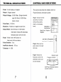
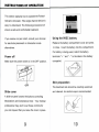
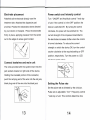
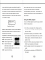
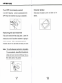
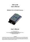
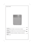
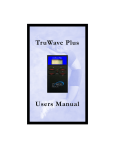
PCS-123T.M.
PULSED-GALVANIC
STIMULATOR
Instruction Manual
CONTENT
23
WARRANTY
22
SERVICE
21
TROUBLESHOOTING
9
INSTRUCTIONS OF OPERATION
8
CONTROLS AND INDICATIONS
7
TECHNICAL SPECIFICATIONS
3
SAFETY AND PRECAUTIONS
1
INTRODUCTION
INTRODUCTION
The Pulsed-Galvanic Stimulator is a High Voltage
The LED indicator can show the battery condition
Galvanic system.
and function mode. When turn on the power, the
LED will turn into green color. If the battery power
This device is battery powered and generates
is low, the LED will show red color. In the alternation
small pulses of electrical current. The output signal
mode, the LED will alternate between red and
has a "twin-peak monophasic wave form with a
green color.
fixed duration". Each pulse is much shorter in
duration (5 us) and can achieve much higher
All the selectors, controls, and switches are very
voltage than conventional stimulator.
clearly. The user is easy to operate this device by
following the user manual.
The Pulsed-Galvanic stimulator system provides
single channel in a single device package.
The polarity switch sets the polarity of the active
in relation to the dispersive electrode. The active
electrode is the pad that delivers the treatment
current. The dispersive electrode completes the
patient circuit.
The Pulsed-Galvanic stimulator has fully
adjustable amplitude (voltage) and the rate of twin
pulses is adjustable from 2 pairs (two pulses) per
second to 100 pairs per second.
1
SAFETY AND PRECUATIONS
The following warnings and precautions apply to
using the Pulsed-Galvanic stimulator system:
12) Several spasm of the laryngeal and pharyngeal
muscle may occur when the electrodes are
placed across the neck or the mouth. This may
1) Federal law (USA) restricts this device to be
used by or on the order of a physician.
2) Keep this system out of children.
3) Do Not use this device on the patients who
have circulatory impairment.
4) Do not stimulate over the carotid sinus.
be strong enough to close off the airway or
cause difficulty in breathing.
13) Patient should never operate potentially
dangerous machinery such as power saw,
automobiles during treatment period.
14) Some patient may have skin irritation.
5) Do not use this device on the patients who
have demand on pacemaker.
6) Do not use this system on the pregnant women.
7) Do not use this system across the temporal
region.
8) Do not apply to individuals prone to seizure.
9) Do not apply electrode over skin defects.
10) Do not apply this device transcerebrally.
11) Adequate precautions should be taken in the
case of persons with suspected or diagnosed
epilepsy.
Precautions
Precautions should be observed:
1) When there is a tendency to hemorrhage
following acute trauma or fracture.
2) Following recent surgical procedures when
muscle contraction may disrupt the healing
process.
3) When stimulating over the menstruating uterus.
Where sensory nerve damage is present resulting
in a loss of normal skin sensation.
4
Additional precautions
Adverse Reactions:
1) Avoid adjusting controls while operating
Possible allergic reaction to tape or gel. Possible
machinery or vehicle.
2) Turn the system off before applying or removing
skin irritation under electrode. If skin irritation
persists, discontinue use and consult a physician.
electrodes.
3) Do not immerse the stimulator in the water or
other liquid.
4) Do not use the stimulator on any muscle or for
any purpose other than that for which it was
prescribed.
5) Do not use the device on any individuals other
than those for whom the device has been
prescribed.
6) Stimulations over areas where bone is near
the skin can be painful in some patients. Be
sure to adjust amplitude slowly.
7) If treatment is ineffective or uncomfortable,
discontinue therapy and consult your physician
or therapist.
8) For external use only.
9) Do not use over the eyelids.
6
TECHNICAL SPECIFICATIONS
CONTROLS AND INDICATIONS
Power : 9 volt battery or Adaptor
This section describes the related switch on
Output : Single channel
Pulsed-Galvanic stimulator system.
Output Voltage : 0-240V Max. (Single channel,
load 500 Ohm) 0-350V Max.
(Open circuit)
Figure 1 shows the front
side oftors, the mode
(left) and the polarity
Pulse Rate : 2-100 Hz
(right), on the display
Waveform : Positive or negative wave form.
board.
Output Mode : Synchronous or Alternation.
Altermation /
Synchronous
Wave Form : Positive /
Negative
Alternation mode-LED alternates
between green and red color.
Power : Green color LED-power on.
Jack Red (+) Receptacle
Red color LED-low battery.
Pulse Duration : 5 us.
Jack Black (-) Receptacle
Figure 2 there are two
IntraPulse Interval : 100 us.
jacks locate in the right
Tolerance :+/- 20%
side view.
Figure 3 shows the
Indicator Light
frequency control, the
Frequency Control
amplitude control, and
an LED indicator.
On/Off and Amplitude Control
(Current Control)
8
INSTRUCTIONS OF OPERATION
This section explains how to operate the PulsedGalvanic stimulator. This single channel device is
easy to understand. The following procedure will
ensure a safe and comfortable treatment.
If you receive no pain relief, consult your clinician
Using the 9VDC battery
for electrode placement or stimulation mode
Replace the battery compartment cover and press
alternatives.
to close. Insert the battery into the compartment.
If a battery is being used, match the battery
Power off
terminals " + " and " - " to the label in the battery
Make sure the power switch is in the OFF position.
compartmt.
Skin preparation
OFF
Slide cover
The treatment site should be carefully examined
and cleaned. An alcohol wipe is recommended.
A slide-on panel covers the buttons controlling
Modulations and Compliance timer. Your medical
professional may wish to set these controls for
you and request that you leave the cover in place.
10
Electrode preparation
Connect leadwires and electrodes
1) Clean the electrode application sites.
Insert each pin of the lead wire into the female
receptacle of each electrode. The red and black
tipped leads should be inserted into the
electrodes and the black tipped leads should be
inserted into the electrode.
2) Apply gel in an even layer (about as thick as a
match book cover) to the bottom of the electrode.
Output plug
(plugs into
output receptacle)
Red Pin Connectors
(plugs into electrodes)
> + (pos)
-(neg)
Avoid using excessive amount of gel.
Electrode Pin Socket
Electrode-
3) The electrode attached with adhesive tape. Be
sure that all sides are evenly taped and that the
Output plug
(plugs into
output receptacle)
Black Pin Connectors
(plugs into electrodes)
-(neg)
electrode is held firmly against the skin.
Remark: If you use the self-stick electrodes,
then you can skip step 2 and step 3.
11
Electrode Pin Socket
Electrode-
12
Electrode placement
Power switch and Intensity control
Attached active electrode directly over the
Turn " ON/OFF and Amplitude control " knob top
treatment site. Attached the dispersive pad
of unit. If the control is in the OFF position, the
proximal. Position the electrodes where directed
device is switched Off. By turning the control
by your doctor or therapist. Press the electrodes
clockwise, the power will be switched On. The
firmly in place, applying pressure from the center
current strength of the impulses transmitted to
out to the edges to ensue good contact.
the electrodes increases further when the control
is turned clockwise. To reduce the current
strength or switch the device Off, turn the control
counter clockwise to the required setting or OFF
position, respectively. Turn the power on. LED
will be on (green color).
Connect leadwires and main unit
The wires provided with the system insert into the
jack sockets located on right side of the device.
Holding the insulated portion of the connector,
push the red plug end of the wire into the red jack,
black plug end of the wire into the black jack.
Setting the Pulse rate
Set the pulse rate as directed by the clinician.
Pulse rate is adjustable. Turn " Frequency control
" knob top of unit. This controls determine how
13
14
many electrical impulses are applied through the
Set all dails and slowly turn up the amplitude
skin every second. By turning the control clockwise,
until you reach the amount of stimulation
the number of current impulses per second (Hz) for
recommended by the clinician. The duration of
channel can be continually adjusted. Unless
treatment should base on the recommendation of
otherwise instructed, turn the pulse rate control to
the clinician.
the 2-100 Hz range.
Using the 9VDC adaptor
If you use 9VDC adaptor as power supply, please
follow the steps below.
Frequency Control
1) Turn off your stimulator first. Make sure the
Setting the Polarity and Function Mode
stimulator power is OFF. Both intensity knobs
Select the desired polarity and function mode as
are set to "OFF".
directed by the clinician.
2) Take the 9V battery out of stimulator. Make
Adjustable the Alternating/Synchronous, Positive/
sure to take out 9V battery before you use the
Negative of Mode setting.
9VDC adaptor, otherwise the battery may ex-
POS means positive wave.
plode or leak.
NEG means negative wave.
ALT
means Alternation
3) Insert the 9VDC output plug of adaptor into the
9VDC input receptacle of stimulator.
(Alternation mode-LED
alternates between green and red color).
CON means Synchronous.
4) Put the adaptor body into the receptacle of AC
outlet.
5) Then follow the indication of PREPARATION
FOR USE.
15
16
AFTER USE
Turn OFF the intensity control
Uninstall battery
Turn the Frequency control in anticlockwise to
Slide away the battery cover and take out the
OFF when the treatment has been completed..
battery.
Removing wire and electrode
Pull out the wires from the output jacks. Leave the
electrode on skin if another treatment is going to
start in minutes. After a treatment session is
finished, take off the electrode and clean your skin.
Note : The self-adhesive electrode is disposable.
To use repeatedly, please flush the electrode
mildly and leave it air-dried with the gel side up,
then stick back to the paster.
17
18
MAINTENANCE AND CLEANING
Main unit
Battery power indication
Your Pulsed-Galvanic Stimulator device may be
When the battery indicator become red, it means
cleaned by wiping gently with a damp cloth
the battery should be replaced with a new one as
moistened with a mild soapy solution. Never
soon as possible. However, unit will continue to
immerse the unit or allow it to be splashed with
operate for several more hours before
water or other liquids. Wipe lead wires with a
replacement.
damp cloth, as above, if they become soiled.
Electrode and leadwire
Reusable electrodes lose their conductive
properties after repeated uses. They should be
replaced when they no longer conduct properly or
if the gel begins to separate from the rest of the
electrode. Reusable electrodes should be stored
on their protective release liner and in their
resealable bags between uses.
Replacement electrodes, lead wires and batteries
should be ordered through your authorized
stimulation device dealer. Use only replacement
parts recommended by the manufacturer. Other
brands of components may cause less than
satisfactory performance and/or system failure.
19
20
TROUBLESHOOTING
SERVICE
If your Pulsed-Galvanic stimulator device seems
To obtain service, first calls your nearest dealer
to work improperly, use the following guide to
for assistance. You may need to send your
determine what may be wrong.
complete Pulsed-Galvanic stimulator system with
a letter describing the problems.
1) If the LED is off, check the battery condition, or
replace battery with a new one.
2) Are electrodes in proper position?
3) Check lead wires. Make sure all connectors are
firmly seated.
4) Replace cord set with another to check for
broken wires.
5) Check the electrode condition. Following the
electrode manufacture's instructions to check
electrode.
21
22
WARRANTY
We warrant each Pulsed-Galvanic stimulator
system only (excluding lead wires, electrodes, and
battery) for ONE (1) year from defects in materials
and workmanship.
This warranty covers parts and labor for ONE (1)
year. Thereafter until the warranty expires, only
the defective part will be repaired or replaced and
the customer will have to pay for the labor.
This warranty does not cover abuse, accident,
damage resulting from failure to follow operating
instructions and alteration/disassembly other than
by us.
The defective unit must be returned to us postage
prepaid and insured.
We shall not be liable for any direct or indirect
consequential damages resulting from the use of
the unit.
23
BBBB
Manufacturer: Skylark Device & Systems Co., Ltd
2F 8-9, No. 40-2, Sec.1, Minsheng N. Rd,
Guishan Township, Taoyuan County 333, Taiwan
www.skylarkdevice.com
! Manufactured for Pain Management Tech Akron, OH