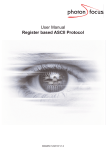
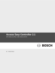
1
Mobile Multimedia Processor Technical Information IMB – YB2 – 000585 Document No. EMMA Mobile TM 1 1/13 Oct 23rd. ,2009 Date issued Mobile Platform Group (MC-10118A、μPD77630A) SoC Systems Division Usage Restrictions Issued by nd 2 SoC Operations Unit NEC Electronics Corporation User’s Manual : Related documents S19598E, S19687E Data Sheet : S19657E, S19686E Notification classification Usage restriction Upgrade Document modification Other notification 1. Affected products MC-10118A, μPD77630A 2. New restrictions [Restriction 5] DDR-SDRAM memory can be used with uPD77630A (only for uPD77630A) [Description] Please use DDR-SDRAM, whose AC spec tXSR (Exit self refresh to first valid command) smaller than 132ns. The products NEC Electronics checked on the data sheet are shown below Vendor Product name Hynix 512Mb_(16Mx32bit) Mobile DDR SDRAM H5MS5122DKA(J3M) Samsung 32Mx32 Mobile DDR SDRAM K4X1G323PE - 8GD6(8) 32Mx32 Mobile DDR SDRAM K4X1G323PC - L(F)E/G ELPIDA 1G bits DDR Mobile RAM EDD10323BBH-LS (32M words × 32 bits) 512M bits DDR Mobile RAM EDD51323DBH-LS (16M words × 32 bits) tXSR(ns) 120(min) 120(min) 120(min) 120(min) 120(min) [Restriction 6] Clock setting at QR (Quick Recovery) operation of ACPU [Description] Using QR (Quick Recovery) operation, the division setting of ACPU clock is just the same as HBUS clock just before entering QR operation. To change the division setting, please use mode transition of Normal Mode A,B,C,D(see P.221 of EMMA Mobile 1 User’s Manual System Control/General-Purpose I/O Interface). The example below shows Normal Mode A for normal operation and Normal Mode C for QR operation. IMB-YB2-000585 Page 2 of 13 Ordinary operation to QR operation CPU_CLK Normal operation Normal Mode A QR operation Normal Mode C QR operation to Ordinary operation CPU_CLK QR operation Normal Mode C Normal operation Normal Mode A [Restriction 7] Write buffer control in the L2 Cache Controller of ACPU [Description] There is the write buffer (256bit x 2slot) in the L2 Cache controller of ACPU. Before cutting off the power switch of ACPU, please drain the data in the write buffer to DRAM (call this operation as Write Buffer Drain). Sample program for restriction 6 & 7 is shown below. IMB-YB2-000585 Page 3 of 13 No.6 ENTRY(cpu_v6_do_idle) 2: ldr r2, =IO_ADDRESS(MP200_SMU_BASE) ldr r0, =0x00244202 str r0, [r2, #0xf8] ldr r3, [r2, #0x80] @ backup current div slot mov r0, #3 @ change with Normal-C slot str r0, [r2, #0x80] ldr r0, [r2, #0x80] lsr r0, #8 cmp r0, #3 bne 2b ldr r2, =IO_ADDRESS(MP200_L220_BASE) ldr r0, =1f mcr p15, 0, r0, c7, c13, 1 ldr r0, =3f mcr p15, 0, r0, c7, c13, 1 Transition @ modify CPU div rate from normal operation (Normal A) to QR operation (Normal C). The division setting of ACPU clock is just the same as that of HBUS clock. Before executing this, the interrupts should be disable. @ prefetch I cache No.7 @ prefetch I cache Prefetch the I-Cache mov r0, #0 mcr p15, 0, r0, c7, c10, 4 to avoid I-Cache @ drain write buffer Write mov r0, #0x1 str r0, [r2, #0x730] 2: 3: data Buffer after Drain Operation and then execute Write Buffer @ L2 Sync Drain. L2_sync_loop: 1: fetching ldr r0, [r2, #0x730] cmp r0, #0 bne L2_sync_loop mcr p15, 0, r1, c7, c0, 4 b 2f ldr r2, =IO_ADDRESS(MP200_SMU_BASE) str r3, [r2, #0x80] mov pc, lr @ wait for interrupt WFI No.6 @ restore CPU div rate After recovering from WFI, transition from QR operation (Normal C) to normal (Normal A). operation IMB-YB2-000585 Page 4 of 13 [Restriction 8] Power switch (L1, L2, L3) control [Description] Power switch of the power domain L1, L2 and L3 should be controlled by setting the registers of each power switch and burrier gate control respectively. - L1&L2 should be controlled by PMU. Please implement the sequence below. - L3 should be controlled by ACPU. Please implement the sequence below. 【L1 Power Off】 Execute below sequence on PMU PMU code PMU command Macro Select Register name Write Data Count 0x000A0268, 0x00000000, REG_WRITE ASMU L1_BUZ 0x00000000 0x000A026C, 0x00000000, REG_WRITE ASMU L1_BUZ2 0x00000000 0x000A0244, 0x00000F0F, REG_WRITE ASMU L1 burrier gate valid ↑ L1_POWERSW 0x00000F0F All of the L1 power switch OFF 【L1 Power On】 Execute below sequence on PMU PMU code PMU command Macro Select Register name ASMU Write Data Count 0x000A0244, 0x00000F07, REG_WRITE L1_POWERSW 0x00000F07 One of the L1 power switch ON 0x4C000050, CYCLE_WAIT 0x000A0244, 0x00000F03, REG_WRITE 0x4C000050, CYCLE_WAIT 0x000A0244, 0x00000F01, REG_WRITE 0x4C000050, CYCLE_WAIT 0x000A0244, 0x00000F00, REG_WRITE 0x4C000050, CYCLE_WAIT 0x000A0244, 0x00000700, REG_WRITE 0x4C000050, CYCLE_WAIT 0x000A0244, 0x00000300, REG_WRITE 0x4C000050, CYCLE_WAIT 0x000A0244, 0x00000100, REG_WRITE 0x4C000050, CYCLE_WAIT 0x000A0244, 0x00000000, REG_WRITE 0x4C000050, CYCLE_WAIT 0x000A0208, 0x01000000, REG_WRITE ASMU 0x000A0268, 0x00001111, REG_WRITE ASMU L1_BUZ 0x00001111 ↑ 0x000A026C, 0x00000011, REG_WRITE ASMU L1_BUZ2 0x00000011 ↑ 0x000A0208, 0x00000000, REG_WRITE ASMU ASMU_BGCTRL 0x00000000 ↑ 0x50 Wait ASMU ↑ L1_POWERSW 0x00000F03 0x50 ASMU ↑ L1_POWERSW 0x00000F01 0x50 ASMU ↑ ↑(All of the L1 power switch ON) L1_POWERSW 0x00000000 0x50 ASMU_BGCTRL 0x01000000 ↑ ↑ L1_POWERSW 0x00000100 0x50 ASMU ↑ ↑ L1_POWERSW 0x00000300 0x50 ASMU ↑ ↑ L1_POWERSW 0x00000700 0x50 ASMU ↑ ↑ L1_POWERSW 0x00000F00 0x50 ASMU ↑ ↑ L1 burrier gate invalid IMB-YB2-000585 Page 5 of 13 【L2 Power Off】 Execute below sequence on PMU PMU code PMU command MacroSelect Register name Write Data Count 0x000A0500, 0x00000000, REG_WRITE ASMU L2_POWERSW 0x00000000 L2 burrier gate valid 0x000A0500, 0x000000FF, REG_WRITE ASMU L2_POWERSW 0x000000FF All of the L2 power switch ON 【L2 Power On】 Execute below sequence on PMU PMU code PMU command MacroSelect Register name 0x000A0500, 0x0000007F, REG_WRITE 0x4C000010, CYCLE_WAIT 0x000A0500, 0x0000003F, REG_WRITE 0x4C000010, CYCLE_WAIT 0x000A0500, 0x0000001F, REG_WRITE 0x4C000010, CYCLE_WAIT 0x000A0500, 0x0000000F, REG_WRITE 0x4C000010, CYCLE_WAIT 0x000A0500, 0x00000007, REG_WRITE 0x4C000010, CYCLE_WAIT 0x000A0500, 0x00000003, REG_WRITE 0x4C000010, CYCLE_WAIT 0x000A0500, 0x00000001, REG_WRITE 0x4C000010, CYCLE_WAIT 0x000A0500, 0x00000000, REG_WRITE 0x4C000010, CYCLE_WAIT 0x000A0500, 0x00010100, REG_WRITE ASMU Write Data Count L2_POWERSW 0x0000007F One of the L2 power switch ON 0x10 Wait ASMU ↑ L2_POWERSW 0x0000003F 0x10 ASMU ↑ L2_POWERSW 0x0000001F 0x10 ASMU L2_POWERSW 0x00010100 ↑ ↑(All of the L2 power switch ON) L2_POWERSW 0x00000000 0x10 ASMU ↑ ↑ L2_POWERSW 0x00000001 0x10 ASMU ↑ ↑ L2_POWERSW 0x00000003 0x10 ASMU ↑ ↑ L2_POWERSW 0x00000007 0x10 ASMU ↑ ↑ L2_POWERSW 0x0000000F 0x10 ASMU ↑ ↑ L2 burrier gate invalid IMB-YB2-000585 Page 6 of 13 【L3 Power Off】 Execute below sequence on ACPU Register Name Write Data ASMU_L3_POWERSW_BUZ 0x00000000 L3 burrier Valid ASMU_L3_POWERSW_BUZ 0x000000FF All of L3 power switch Off 【L3 Power On】 Execute below sequence on ACPU Register Name Write Data ASMU_L3_POWERSW_BUZ 0x0000007F ASMU_L3_POWERSW_BUZ 0x0000003F ↑ ASMU_L3_POWERSW_BUZ 0x0000001F ↑ ASMU_L3_POWERSW_BUZ 0x0000000F ↑ ASMU_L3_POWERSW_BUZ 0x00000007 ↑ ASMU_L3_POWERSW_BUZ 0x00000003 ↑ ASMU_L3_POWERSW_BUZ 0x00000001 ↑ ASMU_L3_POWERSW_BUZ 0x00000000 ↑ ASMU_L3_POWERSW_BUZ 0x00010100 [Restriction 9] USB [Description] One of L3 power Switch On L3 burrier gate invalid D- pin pull-down control USB D- pin in EM1 is always pull-down with 15kohm when device mode is used. To use USB without D- pin pull-down, after Initializing, please RUN(=USBCMD register, bit0(R/S)=1), then set the value=0x600e0001 to USBViewport register. 3. List of restrictions See Appendix 4. History EMMA Mobile1 restrictions documents Document number IMB-YB2-000509 Issue date July 3rd. 2009 Note 1st. edition IMB-YB2-000585 Page 7 of 13 <Appendix: List of restrictions> 1. Detail of restrictions No. 1 Item AXI bus 2 3 GPIO DTV 4 NTSC 5 DRAM 6 ACPU 7 8 9 ACPU Power SW USB Outline MC-10118A uPD77630A After a bus master of AXI(except ACPU) bus reads SRC, the bus master can not read other slave. The FIQ interrupts of GPIO[96:117] do not work. After stopping DMA transfer to DTV module, DTV module continues to send transfer request to AHB bus under the specific conditions. Indication of 1st FIELD (even field) and 2nd FIELD (odd field) reverses NTSC output. The AC spec(TXSR: Exit self refresh to first valid command) of DDR-SDRAM restriction Clock setting at QR(Quick Recovery) operation of ACPU Write buffer control in the L2 Cache Controller Power switch(L1,L2,L3) control D- pin pull-down control [Restriction 1 ] AXI bus [Description] When a bus master of AXI (except ACPU) bus reads SRC (ISRAM 128KB), the bus master can not read other slave after read access to SRC.. [Conditions] - The bus master can read SRC continuously.. - Bus masters can read/write other slaves except SRC. - ACPU (one of the bus master) can read/write SRC without problem. - Bus masters can write slaves including SRC.. [Workaround] - Bus masters which access to SDRAM (one of bus slaves) shall not read SRC . - Bus master (PDMA) which access to SRC shall not read SDRAM. [Restriction 2 ] FIQ interruption of GPIO [Description] The FIQ interrupts of GPIO[96:117] do not work. GPIO[96:117] can be used as IRQ interrupt. IMB-YB2-000585 Page 8 of 13 [Workaround] Use GPIO[0-95] as FIQ interrupt. [Restriction 3 ] DMA transmission of DTV [Description] After stopping DMA transfer to DTV module, DTV module continues to send transfer request to AHB bus under the specific conditions. [Workaround] When DTV module user wants to stop DMA transfer to DTV module, use HW_RSTZ of DT_MODULECONT register (4015_0040H) instead of using DTVSTOP of_DT_STATUS register (4015_0000H). After stopping DMA transfer, reset (HW reset) DTV module if DTVSTOPRAW of DT_RAWSTATUS register (4015_0004H) is 1 and DMAREQ of DT_DMAREQ register (4015_0024H) is 1. (This workaround is supported in NEC EL device driver for Linux) [Restriction 4 ] Indication abnormality of NTSC output [Description] Indication of 1st FIELD (even field) and 2nd FIELD (odd field) reverses NTSC output. - BTB.656 (Right format) - Wrong format 263 263 5 1 1 264 264 2 2 265 265 20 21 I 20 T 283 U 262 263 - R 21 284 B T I 283 T - 284 U R 6 524 5 6 262 525 263 B T 524 6 6 525 × 1st FIELD 2nd FIELD [Workaround] 1stFIELD (even field) and 2ndFIELD (odd field) are exchanged by software (This workaround is supported in NEC EL device driver for Linux). IMB-YB2-000585 Page 9 of 13 [Restriction 5] DDR-SDRAM memory can be used with uPD77630A (only for uPD77630A) [Description] Please use DDR-SDRAM, whose AC spec tXSR (Exit self refresh to first valid command) smaller than 132ns. The products NEC Electronics checked on the data sheet are shown below Vendor Product name Hynix 512Mb_(16Mx32bit) Mobile DDR SDRAM H5MS5122DKA(J3M) Samsung 32Mx32 Mobile DDR SDRAM K4X1G323PE - 8GD6(8) 32Mx32 Mobile DDR SDRAM K4X1G323PC - L(F)E/G ELPIDA 1G bits DDR Mobile RAM EDD10323BBH-LS (32M words × 32 bits) 512M bits DDR Mobile RAM EDD51323DBH-LS (16M words × 32 bits) tXSR(ns) 120(min) 120(min) 120(min) 120(min) 120(min) [Restriction 6] Clock setting at QR(Quick Recovery) operation of ACPU [Description] Using QR(Quick Recovery) operation, the division setting of ACPU clock is just the same as HBUS clock just before entering QR operation. To change the division setting, please use mode transition of Normal Mode A,B,C,D(see P.221 of EMMA Mobile 1 User’s Manual System Control/General-Purpose I/O Interface). The example below shows Normal Mode A for normal operation and Normal Mode C for QR operation. Ordinary operation to QR operation CPU_CLK Normal operation Normal Mode A QR operation Normal Mode C QR operation to Ordinary operation CPU_CLK QR operation Normal Mode C Normal operation Normal Mode A [Restriction 7] Write buffer control in the L2 Cache Controller of ACPU [Description] There is the write buffer(256bit x 2slot) in the L2 Cache controller of ACPU. Before cutting off the power switch of ACPU, please drain the data in the write buffer to DRAM(call this operation as Write Buffer Drain). Sample program for restriction 6 & 7 is shown below. IMB-YB2-000585 Page 10 of 13 No.6 ENTRY(cpu_v6_do_idle) 2: ldr r2, =IO_ADDRESS(MP200_SMU_BASE) ldr r0, =0x00244202 str r0, [r2, #0xf8] ldr r3, [r2, #0x80] @ backup current div slot mov r0, #3 @ change with Normal-C slot str r0, [r2, #0x80] ldr r0, [r2, #0x80] lsr r0, #8 cmp r0, #3 bne 2b ldr r2, =IO_ADDRESS(MP200_L220_BASE) ldr r0, =1f mcr p15, 0, r0, c7, c13, 1 ldr r0, =3f mcr p15, 0, r0, c7, c13, 1 Transition @ modify CPU div rate from normal operation (Normal A) to QR operation (Normal C). The division setting of ACPU clock is just the same as that of HBUS clock. Before executing this, the interrupts should be disable. @ prefetch I cache No.7 @ prefetch I cache Prefetch the I-Cache mov r0, #0 mcr p15, 0, r0, c7, c10, 4 to avoid I-Cache @ drain write buffer Write mov r0, #0x1 str r0, [r2, #0x730] 2: 3: data Buffer after Drain Operation and then execute Write Buffer @ L2 Sync Drain. L2_sync_loop: 1: fetching ldr r0, [r2, #0x730] cmp r0, #0 bne L2_sync_loop mcr p15, 0, r1, c7, c0, 4 b 2f ldr r2, =IO_ADDRESS(MP200_SMU_BASE) str r3, [r2, #0x80] mov pc, lr @ wait for interrupt WFI No.6 @ restore CPU div rate After recovering from WFI, transition from QR operation (Normal C) to normal (Normal A). operation IMB-YB2-000585 Page 11 of 13 [Restriction 8] Power switch (L1,L2,L3) control [Description] Power switch of the power domain L1,L2 and L3 should be controlled by setting the registers of each power switch and burrier gate control respectively. - L1&L2 should be controlled by PMU. Please implement the sequence below. - L3 should be controlled by ACPU. Please implement the sequence below. 【L1 Power Off】 Execute below sequence on PMU PMU code PMU command Macro Select Register name Write Data Count 0x000A0268, 0x00000000, REG_WRITE ASMU L1_BUZ 0x00000000 0x000A026C, 0x00000000, REG_WRITE ASMU L1_BUZ2 0x00000000 0x000A0244, 0x00000F0F, REG_WRITE ASMU L1 burrier gate valid ↑ L1_POWERSW 0x00000F0F All of the L1 power switch OFF 【L1 Power On】 Execute below sequence on PMU PMU code PMU command Macro Select Register name Write Data Count 0x000A0244, 0x00000F07, REG_WRITE ASMU L1_POWERSW 0x00000F07 One of the L1 power switch ON 0x4C000050, CYCLE_WAIT 0x000A0244, 0x00000F03, REG_WRITE 0x4C000050, CYCLE_WAIT 0x000A0244, 0x00000F01, REG_WRITE 0x4C000050, CYCLE_WAIT 0x000A0244, 0x00000F00, REG_WRITE 0x4C000050, CYCLE_WAIT 0x000A0244, 0x00000700, REG_WRITE 0x4C000050, CYCLE_WAIT 0x000A0244, 0x00000300, REG_WRITE 0x4C000050, CYCLE_WAIT 0x000A0244, 0x00000100, REG_WRITE 0x4C000050, CYCLE_WAIT 0x000A0244, 0x00000000, REG_WRITE 0x4C000050, CYCLE_WAIT 0x000A0208, 0x01000000, REG_WRITE ASMU 0x000A0268, 0x00001111, REG_WRITE ASMU L1_BUZ 0x00001111 ↑ 0x000A026C, 0x00000011, REG_WRITE ASMU L1_BUZ2 0x00000011 ↑ 0x000A0208, 0x00000000, REG_WRITE ASMU ASMU_BGCTRL 0x00000000 ↑ 0x50 Wait ASMU ↑ L1_POWERSW 0x00000F03 0x50 ASMU ↑ L1_POWERSW 0x00000F01 0x50 ASMU ↑ ↑(All of the L1 power switch ON) L1_POWERSW 0x00000000 0x50 ASMU_BGCTRL 0x01000000 ↑ ↑ L1_POWERSW 0x00000100 0x50 ASMU ↑ ↑ L1_POWERSW 0x00000300 0x50 ASMU ↑ ↑ L1_POWERSW 0x00000700 0x50 ASMU ↑ ↑ L1_POWERSW 0x00000F00 0x50 ASMU ↑ ↑ L1 burrier gate invalid IMB-YB2-000585 Page 12 of 13 【L2 Power Off】 Execute below sequence on PMU PMU code PMU command MacroSelect Register name Write Data Count 0x000A0500, 0x00000000, REG_WRITE ASMU L2_POWERSW 0x00000000 L2 burrier gate valid 0x000A0500, 0x000000FF, REG_WRITE ASMU L2_POWERSW 0x000000FF All of the L2 power switch ON 【L2 Power On】 Execute below sequence on PMU PMU code PMU command MacroSelect Register name 0x000A0500, 0x0000007F, REG_WRITE 0x4C000010, CYCLE_WAIT 0x000A0500, 0x0000003F, REG_WRITE 0x4C000010, CYCLE_WAIT 0x000A0500, 0x0000001F, REG_WRITE 0x4C000010, CYCLE_WAIT 0x000A0500, 0x0000000F, REG_WRITE 0x4C000010, CYCLE_WAIT 0x000A0500, 0x00000007, REG_WRITE 0x4C000010, CYCLE_WAIT 0x000A0500, 0x00000003, REG_WRITE 0x4C000010, CYCLE_WAIT 0x000A0500, 0x00000001, REG_WRITE 0x4C000010, CYCLE_WAIT 0x000A0500, 0x00000000, REG_WRITE 0x4C000010, CYCLE_WAIT 0x000A0500, 0x00010100, REG_WRITE ASMU Write Data Count L2_POWERSW 0x0000007F One of the L2 power switch ON 0x10 Wait ASMU ↑ L2_POWERSW 0x0000003F 0x10 ASMU ↑ L2_POWERSW 0x0000001F 0x10 ASMU L2_POWERSW 0x00010100 ↑ ↑(All of the L2 power switch ON) L2_POWERSW 0x00000000 0x10 ASMU ↑ ↑ L2_POWERSW 0x00000001 0x10 ASMU ↑ ↑ L2_POWERSW 0x00000003 0x10 ASMU ↑ ↑ L2_POWERSW 0x00000007 0x10 ASMU ↑ ↑ L2_POWERSW 0x0000000F 0x10 ASMU ↑ ↑ L2 burrier gate invalid IMB-YB2-000585 Page 13 of 13 【L3 Power Off】 Execute below sequence on ACPU Register Name Write Data ASMU_L3_POWERSW_BUZ 0x00000000 L3 burrier Valid ASMU_L3_POWERSW_BUZ 0x000000FF All of L3 power switch Off 【L3 Power On】 Execute below sequence on ACPU Register Name Write Data ASMU_L3_POWERSW_BUZ 0x0000007F ASMU_L3_POWERSW_BUZ 0x0000003F ↑ ASMU_L3_POWERSW_BUZ 0x0000001F ↑ ASMU_L3_POWERSW_BUZ 0x0000000F ↑ ASMU_L3_POWERSW_BUZ 0x00000007 ↑ ASMU_L3_POWERSW_BUZ 0x00000003 ↑ ASMU_L3_POWERSW_BUZ 0x00000001 ↑ ASMU_L3_POWERSW_BUZ 0x00000000 ↑ ASMU_L3_POWERSW_BUZ 0x00010100 [Restriction 9] USB [Description] One of L3 power Switch On L3 burrier gate invalid D- pin pull-down control USB D- pin in EM1 is always pull-down with 15kohm when device mode is used. To use USB without D- pin pull-down, after Initializing, please RUN(=USBCMD register, bit0(R/S)=1), then set the value=0x600e0001 to USBViewport register.