1
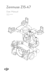
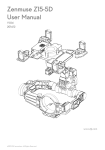
Zenmuse Z15 User Manual V1.9 2012.11.19 Revision www.dji-innovations.com ©2012 DJI Innovations. All Rights Reserved. 1 | Warning & Disclaimer No adjusting or amending is allowed to Z15. Z15 is specialized for Camera and Lens before it leaves the factory. Please mount your camera to Z15 when get it. No adjusting or amending is allowed to Z15. Do not modify or add any other component/device (such as filter, lens hood, etc.) to the camera; make sure to use the original battery; otherwise it may ends up with worse performance or even internal malfunction. Z15 can only work with Autopilot system specified by DJI Innovations (Ace One/ Ace WayPoint/ WooKong M), so as to ensure the highest stability and precision.Please download the corresponding assistant software and upgrade the autopilot system MC firmware, otherwise may lead the Z15 work abnormally. Make sure the Autopilot system operates in the safest manner when the main power battery is connected. We strongly recommend customers to remove all propellers, use power supply from R/C system or flight pack battery, and keep children away during gimbal calibration and parameter setup. Please strictly follow these steps to mount and connect gimbal on your aircraft, as well as to install the assistant software on your computer. Please respect the AMA’s National Model Aircraft Safety Code. As DJI Innovations has no control over use, setup, final assembly, modification (including use of non-specified DJI parts i.e. motors, ESCs, propellers, etc.) or misuse, no liability shall be assumed nor accepted for any resulting damage or injury. By the act of use, setup or assembly, the user accepts all resulting liability. DJI assumes no liability for damage(s) or injuries incurred directly or indirectly from the use of this product. DJI and Zenmuse is registered trademark of DJI Innovations Names of product, brand, etc., appearing in this manual are trademarks or registered trademarks of their respective owner companies. This product and manual are copyrighted by DJI Innovations with all rights reserved. No part of this product or manual shall be reproduced in any form without the prior written consent or authorization of DJI Innovations. No patent liability is assumed with respect to the use of the product or information contained herein. Note1: Upgrade WooKong M firmware to V5.08 or above, ACE ONE firmware to V4.02 or above, or ACE WayPoint firmware to V4.02 or above. Note2: Specified Camera and Lens Type list for Z15-N and Z15-G. (Items in gray italics font are not yet supported at present.) Z15 Type Z15-N Camera Type Z15-G SONY Panasonic Lens Type NEX-5N NEX-7 Supported GH2 Lumix G14 mm/F2.5 E 16mm f/2.8(SEL16F28) Lumix G20 mm/F1.7 Not yet supported Sonnar T*E 24mm F1.8 ZA Lumix G 1:2.5 / 14 ASPH Note3: All diagrams in the manual are for SONY NEX-5N with SEL16F28 unless stated, since different camera or lens should use special component. ©2012 DJI Innovations. All Rights Reserved. 2 Product Profile Z15 is an excellent gimbal designed for AP. The gimbal has built-in slip ring in the mechanical structure, preventing wire rod from winding up. It also has built-in independent IMU module, special servos drive module, HDMI- AV module, etc. Excellent job can be done by Z15 in any working mode, including Orientation-locked control, Non orientation-locked control and FPV Mode (Reset). Z15 Working Mode Non orientation-locked FPV Mode Mode (Reset) Orientation-locked Mode Gimbal pointing stays Gimbal Gimbal pointing pointing stays when aircraft moves Gimbal Pointing the same as aircraft unchanged with aircraft nose direction nose direction when nose moves. power up Gimbal and Gimbal pointing keeps the Relative Aircraft Nose same relative angle with gimbal pointing and aircraft between gimbal pointing aircraft nose direction nose direction may change and aircraft nose Relative Angle TX Control Attitude stability angle between Zero relative angle Controlled Controlled Not controlled YES YES YES YES YES YES Vibration Reduction ROLL is locked level in 0~2/3 command stick and Command stick stands for rotate in 2/3 ~endpoint; gimbal rotation velocity,Stick command stick stands for Stick Meaning center position is for 0,its —— rotation angle limited to +- 45o in PAN; command endpoint is maximum velocity. stick stands for gimbal rotation velocity in TILT. Command YES YES —— Linearity Note1: Gimbal pointing means gimbal PAN rotation direction. Note2: Attitude stability means that gimbal’s ROLL/TILT will not follows the aircraft’s ROLL/PITCH. Note3: Gimbal rotating maximum velocity is corresponding to TX 100%end-point. ©2012 DJI Innovations. All Rights Reserved. 3 In Box Gimbal ×1 In the mechanical structure, the gimbal has built-in slip rings, preventing wire rod from winding up, which also enables free rotations for the 3 axes rotating rods. The gimbal has built-in Z15 gimbal special servos drive module, independent IMU module and HDMI-AV module. Gimbal Controller Unit (GCU)×1 Connect the gimbal controller to the autopilot system by CAN bus. The GCU will control the gimbal’s pan, roll and tilt axes rotation. Lens Retaining Ring×1, L-Connector ×1(Z15-N) For fixing the camera lens. (With jackscrew ×2) Lens Retaining Ring Shim×1(Z15-N) For fastening the camera lens. Mounting Bracket ×4 For gimbal and bi-pod connection. Camera Mount Screw×1 For camera mount. Lens Retaining Ring Screw×1(Z15-N) For fixing the lens retaining ring to the gimbal. Hot Shoe ×1(Z15-G) For fastening the camera to gimbal. ©2012 DJI Innovations. All Rights Reserved. 4 Quick Twist Screw for Hot Shoe ×1(Z15-G) For fixing the hot shoe to camera. Quick Twist Screw for Camera ×1(Z15-G) For fixing the camera to gimbal. Screw×10(Z15-N) or Screw×8(Z15-G) For mounting gimbal to aircraft (2.5*8 Head-cup screw×8). (OnlyZ15-N needs)For fixing the lens retaining ring (M2.5*5 Screw×2). Gimbal Video Power Cable×1 For gimbal controller and Wireless Video Transmission Unit connecting, transmitting AV signal. Micro-USB Cable×1 For adjusting parameter and upgrading firmware via PC. DJI Use CAN-Bus to power and communicate with the autopilot DJI CAN-Bus Cable×1 system. Spare Package×1 Damping units, Spare Screw, and Mounting Bracket. Note: there are different between Z15-N and Z15-G. ©2012 DJI Innovations. All Rights Reserved. 5 Contents WARNING & DISCLAIMER ...............................................................................................2 PRODUCT PROFILE ..........................................................................................................3 IN BOX ............................................................................................................................4 CONTENTS ......................................................................................................................6 MATTERS NEED ATTENTION............................................................................................7 GIMBAL DESCRIPTION ....................................................................................................8 CAMERA SETUP ............................................................................................................ 10 MOUNT ........................................................................................................................ 12 CAMERA WIRING/SHUTTER CONTROL ......................................................................... 15 VIDEO SIGNAL TRANSMISSION ..................................................................................... 17 GIMBAL CONTROLLER WIRING ..................................................................................... 18 WORKING MODES/HDMI/AUX2/AUX3 SWITCH SETUP ...................................................... 20 ASSISTANT .................................................................................................................... 22 TEST ............................................................................................................................. 25 APPENDIX ..................................................................................................................... 27 1-PILOT SOLUTION .............................................................................................................. 27 2-PILOT SOLUTION ..............................................................................................................28 PORT DESCRIPTION ..............................................................................................................29 GIMBAL LED INDICATOR .......................................................................................................30 GIMBAL L ABEL DESCRIPTION .................................................................................................30 TROUBLE SHOOTING ............................................................................................................31 SPECIFICATIONS ...................................................................................................................32 ©2012 DJI Innovations. All Rights Reserved. 6 Matters Need Attention For safety reasons, please pay serious attention to all following items: Ensure nothing blocks the servo driver module rotation, to avoid motor damage. Camera’s HDMI resolution should be set to 1080i. Ensure to mount the side of servo driver module1 without ports to the aircraft nose direction. The gimbal center of gravity has been set, whose position directly determine gimbal performance. Please do not adjust the gimbal center of gravity by yourself. The gimbal is a high-precision control device. Do not remove any other screws in the gimbal, which may result in bad performance or even damage. Do not unplug any cable attaching to the gimbal ports, or even change the mechanical structure. Make sure all wiring is correct, otherwise may lead to gimbal abnormal work or even out of control. Make sure to connect Video Transmission Unit to gimbal controller before power on the system. The standard gimbal video power cable is recommended. Make sure you solder the gimbal video power cable to the wireless video transmission unit correctly, to avoid the 12V power burn the gimbal or your own device. And ensure the cables are insulated, to prevent from short circuit. Ensure the 12V power is safe for you own device when other power cable is used. Make sure the wireless video transmission module current consumption does not exceed 1A, to prevent GCU from damage. Pay attention to that S800 power supply voltage is within the defined limits (6S), when using one battery for both S800 and Gimbal power supply. Different camera or lens should use special component. Prevent the Gimbal from the power cable; otherwise it may lead to the short circuit of the Gimbal. ©2012 DJI Innovations. All Rights Reserved. 7 Gimbal Description Notices: Ensure nothing blocks the servo driver module rotation, to avoid motor damage. Clear obstacle at once if the rotating gimbal is blocked. Tips: Servo driver module is with two motor command input ports and one encoder private port. HDMI-AV module converts HDMI video signal to AV video signal with a cable connecting to camera HDMI port; also transforms TX signal into shutter control signal with a shutter control module. (Z15-N)Shutter control module is for camera shutter control using an infrared signal emission head. Please read the related content according to your product (Z15-N or Z15-G). Z15-N Pan ±360° continuous rotation Mounting Bracket Motor Command Input Port (To GCU G6) Servo Driver Module 1 Damping Unit Port of 8-Pin Cable (To GCU G8) Servo Driver Module 3 Servo Driver Module 2 HDMI-AV Port Cameral Mount Position Lens Retaining Ring Lens Retaining Ring Shim Camera Mount Screw-hole Roll Shutter Control Module ±40° (±360° mechanic continuous rotation) HDMI-AV Module Gimbal LED Indicator IMU Module Servo Driver Module Port ±360° continuous rotation Tilt ©2012 DJI Innovations. All Rights Reserved. Motor Command Input Port Encoder Private Port 8 Z15-G Pan ±360° continuous rotation Mounting Bracket Motor Command Input Port (To GCU G6) Servo Driver Module 1 Damping Unit Port of 8-Pin Cable (To GCU G8) Servo Driver Module 3 HDMI-AV Port Servo Driver Module 2 Cameral Mount Position Hot Shoe Camera Mount Screw-hole Roll Shutter Control Cable ±40° (±360° mechanic continuous rotation) Gimbal LED Indicator HDMI-AV Module IMU Module Servo Driver Module Port ±360° continuous rotation Tilt ©2012 DJI Innovations. All Rights Reserved. Motor Command Input Port Encoder Private Port 9 Camera Setup Configure your camera by following the settings, meeting the requirements of Z15. Please read the related content according to your product (Z15-N or Z15-G). Sony NEX-5N /7 Menu Shot Mode Camera Image Size Brightness/ Color Playback Setup Shot Mode Camera Manual Exposure Drive Mode M AF/MF Select 1/60 Shutter Aperture Brightness/Color Remote Cdr. ISO MF Not use Auto White Balance Not use Auto Setup Lens Comp: Shading Lens Comp: Distortion Off HDMI Resolution F3.5 Off Lens Comp: Chro.Aber Off Please set Shot Mode as Manual Exposure M. Shutter: Value 1/15~1/80 is recommended, do not set it bellow 1/80(like 1/120). Aperture: According to exposure degree. Drive Mode: Set as Remote Cdr., so that camera shutter can be controlled by TX. AF/MF Select: Select MF, otherwise output image would be flashing. ISO: Please fix a certain value instead of automatically. White Balance: Please do not set it to auto white balance mode. Lens Comp: Set Shading/Chro.Aber/Distortion Off. HDMI Resolution: Should be set to 1080i. 1080i Panasonic GH2 iA A P SC N M C3 C2 C1 M S MF AFC AFS Please set Shot Mode as Manual Exposure M. MF/AFC/AFS Select: Select MF。 Using the MOTION PICTURE Mode Menu, set the REC MODE as AVCHD(1080i)。 ©2012 DJI Innovations. All Rights Reserved. 10 Tips: In the Menu settings, the mandatory values are in red italic font while recommended values in blue. Notices: Flashing image output may occur if not follow the recommended settings. ©2012 DJI Innovations. All Rights Reserved. 11 Mount Mount Lens(Z15-N)/ Mount Hot Shoe(Z15-G) Please read the related content according to your product (Z15-N or Z15-G). For Z15-N, please read Mount Lens, otherwise read Mount Hot Shoe for Z15-G. Mount Lens (Z15-N) Step1 Step2 Step3 Screw L-Connector Jackscrew Camera Retaining Ring Lens Mark align align Shim Step1: Put retaining ring through lens before mounting onto camera, accurate the alignment by matching the mark. Step2: Slip the shim between lens and retaining ring, fix in (but not tighten) screws (M2.5*5 Screw×2). Step3: The L-Connector is active. Mount Hot Shoe (Z15-G) Step1 Step2 Step3 Quick Twist Screw for Hot Shoe Hot Shoe Camera Step1: Insert the hot shoe into the camera. Step2: Adjust the hot shoe and fix the quick twist screw. Step3: Finished. ©2012 DJI Innovations. All Rights Reserved. 12 Mount Camera into Gimbal Please read the related content according to your product (Z15-N or Z15-G). Z15-N Retaining Ring Screw Jackscrews and Other Screws Camera Mounting Screw Step4: Mount the camera into the gimbal and tighten the camera mounting screw. Step5: Adjust the L-Connector, and fix the retaining ring screw. Step6: Tighten the jackscrews and other screws. Z15-G: Quick Twist Screw for Camera Camera Mounting Screw Step4: Mount the camera into the gimbal. Step5: Adjust the camera and tighten the camera mounting screw. Step6: Tighten the quick twist screw for camera. ©2012 DJI Innovations. All Rights Reserved. 13 Mount Gimbal to Bi-pod Following diagram shows mounting gimbal to DJI Innovations S800 bi-pod. You may mount the gimbal to a bi-pod prepared by you referring to the following diagram. Screws Mounting Bracket Parallel N raft Airc ose Camera Gimbal Lens X Y Step7: Z DJI S800 Bi-pod Install gimbal to a bi-pod with mounting bracket; tighten up screws (2.5*8 Head-cup screw×8) with appropriate screw glue. Notices: Ensure to mount the side of servo driver module1 without ports to the aircraft nose direction. Make sure the top and bottom plates of damping unit stay parallel when mounting, preventing the damping units from stretched and distorted. Keep overall balance when mounting, in order to make the center of gravity on the red line (Z axis). The gimbal center of gravity has been set, whose position directly determine gimbal performance. Please do not adjust the gimbal center of gravity by yourself. The gimbal is high-precision controlled. Do not remove any other screws in the gimbal, which may result in bad performance or even damage. Do not unplug any cable attaching to the gimbal ports, or even change the mechanical structure. Make sure the wiring is correct, otherwise may lead to gimbal abnormal work or even out of control. ©2012 DJI Innovations. All Rights Reserved. 14 Camera Wiring/Shutter Control Camera Wiring Connect the camera correctly, since the gimbal works with a HDMI-AV module for converting video signal format and transforming TX signal into shutter control signal. Please read the related content according to your product (Z15-N or Z15-G). Ensure camera is setup first, and then follow the procedures to connect camera and gimbal. Z15-N Shutter Control Module Infrared Signal Emission Unit HDMI-AV Module IMU Shutter Remote Sensor Camera Lens HDMI-AV Interface Camera Gimbal LED Indicator Camera HDMI Port Z15-G HDMI-AV Module IMU Shutter Camera Shutter Control Cable Camera Lens HDMI-AV Interface Camera Gimbal LED Indicator Camera HDMI Port Step1: Connect the gimbal HDMI-AV module to camera HDMI port with a HDMI-AV connection cable. Step2: For Z15-N, make sure the infrared signal emission unit is aligned to the remote sensor. For Z15-G, connect the camera shutter control cable to the camera. Notices: ©2012 DJI Innovations. All Rights Reserved. 15 When disconnect the cable between HDMI-AV module and camera, dismount the camera, and unplug the HDMI-AV interface. (Z15-N) Make sure the infrared signal emission unit is aligned to the remote sensor. Shutter Control Z15 enables transforming TX command into shutter control signal, please set one 2-position switch/channel for remote shutter control. For Z15-N, set the Drive Mode as Remote Cdr. in Camera Menu, and make sure the shutter control module is correctly mounted and wired. For Z15-G, make sure camera shutter control cable is correctly wired. Whichever 2-position switch on your transmitter selected, wire the right channel of receiver to SHUT port. One switch toggle is for one shooting. For example, toggle twice will achieve two shootings. Position-1 Position -2:First shooting Position -2Position -1:Second shooting 2-Positon Switch 1 2 Tx Notices: Set the camera of Z15-G to “Manual Video”, the shutter can be used to record video. One toggle is for start/stop recording. The video recording of Z15-N is available by setting the AUX3 channel of the GCU. Please refer to the AUX3 Switch Setup for details. Tips: Following diagram shows how the shutter control works. If the shutter control works abnormally, please check each step. TX RC Receiver TX Command 2-Position Switch Wireless GCU TX Command 2-Position SHUT Switch Channel 3-Pins Cable Camera Shutter Shutter Control Module Control Signal Camera Shutter Wireless Gimbal TX Command HDMI-AV Module Internal Cable Shutter Control Signal Infrared Unit Camera Shutter Control Cable ©2012 DJI Innovations. All Rights Reserved. Z15-N 2-Pins Cable Z15-G 16 Video Signal Transmission A wireless video transmission module is necessary for video signal accessing remotely. Gimbal Video Power Cable Wireless Video Transmission Module Air End Power Video Signal Port Video Signal Power(Red:1A@12V) GND Video Signal(Yellow:AV) GND(Black: ) Step1: Respectively solder the Power/Video Signal/GND cables to wireless video transmission module (Air End). Step2: Plug the gimbal video power cable head into the GCU Video Signal Port. Notices: Make sure to connect Wireless Video Transmission Unit to GCU first, then power on. Set HDMI Resolution as 1080i for Z15-N; set the REC MODE as AVCHD (1080i) using Z15-G; otherwise the wireless video transmission module will work abnormally. The standard gimbal video power cable is recommended. Make sure you solder the gimbal video power cable to the wireless video transmission unit correctly, to avoid the 12V power burn the gimbal or your own device. And ensure the cables are insulated, to prevent from short circuit. Power Cable(1A @12V) Video Signal Cable(AV) GND Cable Ensure the 12V power is safe for you own device when using other power cable. Make sure the wireless video transmission module current consumption does not exceed 1A, to prevent GCU from damage. Tips: Following diagram shows how video signal transit when gimbal working. If video signal access fails, please check each step. Camera GCU Gimbal AV signal HDMI signal HDMI HDMI-AV cable Monitor AV input AV signal AV signal G8 HDMI-AV module Gimbal Video Power Cable 8-Pins cable Wireless video transmission module Ground end Wireless video transmission Wireless signal module 5.8G/2.4G/1.2G Air end Self-prepared by user ©2012 DJI Innovations. All Rights Reserved. 17 Gimbal Controller Wiring GCU Wiring WKM/ ACE ONE/ ACE Waypoint USB Port PC connection for configuration and firmware upgrades with an USB cable. RC Receiver (Aircraft control) Any spare CAN port on DJI autopilot system Battery 2-Position Switch 2-Position Switch (4S~12S) 2-Position Switch AUX2 RUDD RC Receiver (JR) ELEV AILE 8-Channel Or Wireless Video Transition Module Air End Heat Sinks 8-Channel 1 2 4 7 RC Receiver (Futaba 2-Position Switch / Hitec) 2-Position Switch 2-Position Switch Or S-Bus S-Bus Receiver (Futaba) G8 G8 G6 G6 Or PPM PPM Receiver G6 Ensure the side with copper contacts is facing upward towards the heat sinks. Turn to next page to obtain the correspondence between t h e GCU channels and S-Bus/PPM channels. Battery · Connect the XT60 to the GIMBAL on the center frame if DJI S800 used. · Attention that S800 power supply voltage should be within the defined limits (6S), when using one battery for both S800 and Gimbal power supply. · Please refer to S800 User Manual for details. WKM/ACE ONE/ACE Waypoint Please refer to WKM/ACE ONE/ ACE Waypoint User Manual for all connection and configuration details. · · · · · Gimbal Controller (GCU) M ake sure ports are accessible when installing MC so as to facilitate wiring and software configuration. In 3-pin ports, pins near the nicks are signal pins. 6-pin cable for G6, 8-pin cable for G8. DO NOT cover the heat sinks, keep them unobstructed. The IMU module is NOT water-proof or oil-proof. RC Receiver · These are example connections. Prepare 2 TXs, one is for gimbal control, the other one for aircraft control, refer to 2-Pilots Solution for more detail in Appendix. · If one receiver is used for aircraft and gimbal control at the same time, refer to 1-Pilot Solution for detail in Appendix. · Setup Aileron, Elevator, Rudder channels on gimbal control TX. Command stick stands for gimbal rotation velocity, center position is for 0,endpoint for maximum velocity(both clockwise and counter clockwise directions). (End Point is 100%) · Choose one 3-position switch/channel as Z15 working modes switch.(MODE) · Choose one 2- position switch/channel As camera shutter control switch(SHUT), one for HDMI switch(AUX1), one for camera lens orientation switch in Reset Mode (AUX2), and also one for Z15-N video control switch(AUX3). · Please refer to WKM/ACE ONE/ACE Waypoint User Manual for aircraft control setting. · Connect the receiver to GCU correctly. ©2012 DJI Innovations. All Rights Reserved. 18 GCU Ports Indication Following table shows the GCU channels and TX channels connection. TX Channels GCU Indications JR Futaba/Hitec Channels AILE 1 ROLL ELEV 2 TILT For tilt axis control. Velocity is zero if disconnection. RUDD 4 PAN For pan axis control. Velocity is zero if disconnection. AUX2 7 MODE For roll axis control (left/right). Velocity is zero if disconnection. For Working Mode switch. For camera shutter control. Off when non-connection and 2-position switch channel SHUT disconnection. For HDMI-AV conversion switch. Conversion function is on 2-position switch channel AUX1 while non-connection or disconnection. When AUX2 is connected to a 2-position switch channel, it is used as camera orientation (down or forward) switch in FPV 2-position switch channel AUX2 Mode (Reset). The camera orientation is forward while Or Futaba S-Bus channel non-connection or disconnection. If S-Bus receiver is used, it should be connected to AUX2 port. When AUX3 is connected to a 2-position switch channel, it is 2-position switch channel AUX3 used for Z15-N video recording control. Or PPM channel If PPM receiver is used, it should be connected to AUX3 port. Following table shows the corresponding relationship between the GCU and the S-Bus/PPM channels. S-Bus/PPM Channels GCU Channel 1 ROLL 2 TILT 4 PAN 7 MODE 5 SHUT 8 AUX1 9 AUX2 6 AUX3 ©2012 DJI Innovations. All Rights Reserved. 19 Working Modes/HDMI/AUX2/AUX3 Switch Setup Gimbal Working Mode Switch Set Whichever 3-position switch selected as working mode switch, wire the right channel of receiver to MODE port. At each switch position, use end-point fine tuning, set the channel AUX2(JR) /7(Futaba/Hitec) for the three Working modes. Orientation-locked Mode MODE channel end-point 60%~90% FPV Mode (Reset) back to center Non orientation-locked Mode MODE channel end-point 60%~90% Notices: The gimbal will work in Orientation-locked Mode, if not connect to MODE. Gimbal default works in FPV Mode after power on. The gimbal will maintain the Working Mode from last moment, if the cable between MODE and RC receiver is disconnecting while working. Tips: For 3-position switch, you may assign: 3-Position Switch Position-1 to Non orientation-locked Position-2 to FPV Mode (Reset) 1 2 3 Tx Position-3 to Orientation-locked Position-1 and Position-3 can be reverse assigned. One 2-position switch can be assigned for any two of the working modes as you like. HDMI Switch Set HDMI-AV module can be set on/off by TX. Please ensure camera HDMI port is connected to gimbal correctly. Whichever 2-position switch selected as HDMI switch, wire the right channel of receiver to AUX1 port. You may assign: Position-1 to ON; Position-2 to OFF; or reverse the assignment. 2-position switch 1 2 Tx Notices: The camera HDIM will be on if AUX1 and RC receiver is disconnected. ©2012 DJI Innovations. All Rights Reserved. 20 AUX2 Switch Set Z15 supports to control the camera lens down or forward in Reset Mode. Please wire the right channel of receiver to AUX2 port. You may assign: Position-1 to DOWN; Position-2 to FORWARD; or reverse the assignment. 2-position switch 1 2 Tx Notices: This function can only work in FPV Mode (Reset). When this function is on, if the working mode switch from other modes to FPV Mode (Reset), the gimbal will force the camera lens to face forward or down depending on AUX2 Switch. The camera orientation is forward while non-connection or disconnection. Tips: When AUX2 is connected to Futaba S-Bus channel it is used as the S-Bus channel input. AUX3 Switch Set Z15-N supports camera video recording. Please wire the right channel of receiver to AUX3 port. Every toggle is for start/stop recording. Notices: Only Z15-N gimbal needs to set the AUX3 channel when using the camera for video recording. Z15-G gimbal controls the camera to record video by setting the camera to“Manual Video”. ©2012 DJI Innovations. All Rights Reserved. 21 Assistant Install Driver and Software STEP1: Make sure driver is installed correctly, which has been installed before you use WKM,ACE ONE or ACE WAYPOINT. STEP2: Please download assistant software ZenmuseInstaller.exe from DJI Innovations website. STEP3: Double click ZenmuseInstaller.exe file and follow the steps to finish installation. STEP4: Run DJI Zenmuse Assistant. GUI Connect GCU and PC via USB cable, power on GCU. 1 2 1 DJI · Tools: Upgrade. For upgrading the gimbal firmware · Language: 中文or English · Help: About. For version and SN access 2 Gimbal · Basic: For Roll/Tilt/Pan/Mode observation · Function: For Shutter/HDMI/AUX2 observation 3 Connection indicator 5 · Blue LED On: Disconnected with PC · Green LED On: Connected with PC 4 Communication indicator · Blue LED On: Without communication · Green LED Blink: Communicating with PC 4 3 ©2012 DJI Innovations. All Rights Reserved. 5 Text Description · Mouse over each item will display the corresponding content 22 Firmware Upgrade Please strictly follow the operation procedures for firmware upgrade, otherwise Z15 might not work properly: Step1: Make sure your computer is connected to the Internet. Step2: Please close all the other applications during firmware upgrade, including anti-virus software and firewall. Step3: Make sure the power supply is securely connected. DO NOT un-plug the power supply until firmware upgrade has finished. Step4: Connect GCU to PC with a Micro-USB cable, DO NOT break connection until firmware upgrade has finished. Step5: Run Software and wait for connection. Step6: Select DJITools Upgrade. Step7: DJI Innovations server will check current firmware version, and get the latest firmware prepared for the unit. Step8: If there is a firmware version more up-to-date than your current version, you will be able to click the Upgrade button. Step9: Wait until Assistant software finishes reading gimbal and GCU. Step10: Click OK and power cycle the unit after at least 5 seconds. Notices: After firmware upgrade, please re-recognize setup using Assistant software. If abnormally read or write, close software and power off, and then restart software and power up. If it is notified that the network or DJI Innovations server is busy, please try again later with above procedures. If firmware upgrade failed, please try again with the above procedures. Product Information You can check the product version via Help About. This includes Hardware ID,IMU,GCU,Software. SN is a 32 digits authorization code for unit function activations. We had already filled in the authorization code for your unit after manufacture. You might be asking to fill in the new SN in the future if you brought new function upgrades. Fill in the SN and then click Write button. If you filled in an invalid SN over 30 times, your product will be locked and you have to contact our customer support. ©2012 DJI Innovations. All Rights Reserved. 23 Basic Make sure your setups according to Basic. ROLL/PAN/ TILT: Push the joystick on TX to obtain the stick direction and the gimbal rotation direction. If you use the DJI iOSD, you may obtain the gimbal attitude information (PAN/ TILT/ ROLL) on the bottom right corner of the display screen. The following diagram shows the gimbal rotation direction and the cursor slide direction on assistant. PAN axis rotation Cursor slide right Cursor slide left Cursor slide right TILT axis rotation Cursor slide left Cursor slide right Cursor slide left ROLL axis rotation MODE: Toggle the 3-position switch, the corresponding slider of cursor will turn red . Function SHUT/AUX1/AUX2/AUX3 :Toggle the 2-position switch, the corresponding slider of cursor will turn red . ©2012 DJI Innovations. All Rights Reserved. 24 Test Check Before Flight Notices: Gimbal is installed firmly to bi-pod, and camera mounted correctly and stably. All cables are in correct connection, without anyone in backwards. Gimbal video power cable is in good soldered condition if wireless video transmission module used. Correct TX settings. Camera shutter control module is correctly mounted. Correct camera setups. Correct connection between GCU and RC receiver. Normal connection between GCU and autopilot system. Upgrade Autopilot System MC Firmware. Tips: Gimbal LED flashing red quickly when camera and gimbal connection fails. Gimbal LED stays solid green when camera and gimbal is successful connection. Please turn to Trouble Shooting in Appendix if abnormal situation occurs. Test Step1: Ensure batteries are fully charged for transmitter, GCU and all the other devices on your aircraft. Step2: Make sure all connections and wirings are in good condition. Step3: Switch on the TX. Step4: Power on gimbal and wait for self-testing, whose three axes will rotate quickly at the same time. Step5: After self-testing, camera lens will point to aircraft nose direction, that is, the three axes of gimbal should be in the condition as the following diagram shows. Step6: Gimbal goes into initialization, at this time the three axes will rotate very slowly. Step7: Gimbal is at a standstill after initialization, and ready for usage. Step8: Toggle the Working Modes switch on your transmitter, and make sure it is working properly. Step9: Switch the Working Modes to Non orientation-locked, FPV Mode (Reset), Orientation-locked respectively, and then try to push your sticks lightly in Roll, Tilt and Pan to feel if your gimbal moves to the corresponding direction. If not, go back to Gimbal Working mode Switch Set to correct your settings. ©2012 DJI Innovations. All Rights Reserved. 25 Notices: If the gimbal is abnormal (unlike the diagram shows) after initializing, please turn to Trouble Shooting in Appendix. ©2012 DJI Innovations. All Rights Reserved. 26 Appendix 1-Pilot Solution 3-Position Switch 3-Position Switch 3-Position Switch 3-Position Switch 2-Position Switch 2-Position Switch 2-Position Switch 14-Channel RC Receiver (Futaba) Gimbal Control Aircraft Control 1 (AILE) 2 (ELEV) 3 (THRO) 4 (RUDD) 5 (GEAR) 6 (Collective Pitch) 7 (Control Mode Switch) Tx or · · This is example connection. Prepare one 14-channel TX/RC receiver for aircraft and gimbal control. Setup Aileron, Elevator, Throttle,Rudder channels on TX for aircraft roll, elevator, throttle, rudder control, and TX AUX2 for aircraft control modes(Please refer to Autopilot System User Manual). · Choose three 3-position switches for ROLL, TILT, and PAN rotation control. Switch center position is 0 velocity and end positions are maximum velocity. · Choose one 3-position switch/channel as Z15 Working Modes switch (MODE). · Choose one 2-position switch/channel as camera shutter control switch (SHUT), and one as HDMI switch (AUX1). · Connect the receiver to GCU and Autopilot System MC correctly. ©2012 DJI Innovations. All Rights Reserved. 27 2-Pilot Solution Rx1 2-Position Switch Gimbal Control 2-Position Switch 2-Position Switch AUX2 RUDD ELEV AILE RC Receiver (JR) 8-Channel Or 1 2 4 7 Tx1 8-Channel RC Receiver (Futaba / Hitec) 2-Position Switch 2-Position Switch 2-Position Switch Or Aircraft Control Rx2 S-Bus S-Bus Receiver (Futaba) PPM PPM Receiver Or AUX2 RC Receiver (JR) 8-Channel RUDD ELEV AILE THRO AUX2 Or Tx2 1 2 3 4 7 RC Receiver (Futaba / Hitec) 8-Channel Or Futaba S-Bus S-Bus WKM Or ACE ONE ACE Waypoint Rx2 RC Receiver (JR) 8-Channel AUX2 AUX1 GEAR RUDD ELEV AILE THRO AUX2 Or RC Receiver (Futaba / Hitec) 8-Channel or 7 6 5 4 3 2 1 Prepare 2 TXs and 2 RXs. TX1 and RX1 are for gimbal control. TX2 and RX2 are for aircraft control. Please refer to Gimbal Controller Wiring for more details. ©2012 DJI Innovations. All Rights Reserved. 28 Port Description Gimbal Controller ROLL For roll axis control TITL For tilt axis control PAN For pan axis control MODE For Working Mode switch SHUT For camera shutter control AUX1 For HDMI switch AUX2 For Gimbal orientation (down or forward) switch in FPV Mode S-Bus Receiver AUX3 For Z15-N video recording control PPM Receiver To wireless video transmission unit, transmitting AV signal XT60 To battery (To GIMBAL if DJI Innovations S800 used) G6 To Gimbal, transmitting motor command G8 To Gimbal, transmitting video signal Micro-B USB port: PC connection for configuration and firmware upgrades CAN-Bus port: Use CAN-Bus to connect GCU to the autopilot system Gimbal HDMI-AV Port To Camera HDMI port Motor Command To GCU G6 Input Port 8-Pin Cable Port To GCU G8 ©2012 DJI Innovations. All Rights Reserved. 29 Gimbal LED Indicator Description LED Indicator Camera and gimbal connected Camera and gimbal disconnected Gimbal Label Description Camera Type _ Lens Type For example NEX5N_16 Camera Type SONY NEX-5N Lens Type E 16mm f/2.8(SEL16F28) ©2012 DJI Innovations. All Rights Reserved. 30 Trouble Shooting NO. What Why How to (1) TX trims are too much (1) Adjust the TX trims (2)GCU and autopilot system (2)Connect GCU and autopilot is disconnected system (3)Z15 mounting direction is (3)Ensure Z15 mounting direction disaccording to aircraft nose is the same with aircraft nose The gimbal is abnormal Abnormal Please contact local dealer or DJI after initializing manufacture Gimbal keeps drifting 1 after initialization calibration after 2 Innovations customer service Can’t distinguish gimbal 3 Switch to FPV Mode first, then to BVR flight pointing when using another Working Mode needed (1) The gimbal and camera (1)Make sure cable connected disconnected 4 Gimbal LED flashing red (2)Please power on camera (2)Camera is off (3)Set HDMI resolution as 1080i (3) Camera setup failure (1) Wireless video (1) Check the wireless video transmission unit disconnected transmission unit connection (2)Wrong power supply for (2) Ensure the power supply for wireless wireless video transmission unit is Gimbal green LED is on 5 but without video display unit ©2012 DJI Innovations. All Rights Reserved. video transmission 12V 31 Specifications General Built-In Functions Three Working Modes Orientation-locked control Non orientation-locked control FPV mode (Reset) Built-in independent IMU module DJI gimbal special servos drive module HDMI- AV module Wireless video transmission support Camera shutter control support Z15-N video recording control support Wide range voltage input support S-Bus/PPM Receiver support SONY NEX-5N SONY NEX-7 Panasonic GH2 SONY: E 16mm f/2.8(SEL16F28) Panasonic: Lumix G14 mm/F2.5 Peripheral Supported Camera Supported Lens Currently Lumix G20 mm/F1.7 GCU Input Power 4S~12S LiPo (Recommend 6S if with S800) Control Requirement Four spare receiver channels at least Assistant Software System Requirement Windows XP SP3; Windows 7 Mechanical& Electrical Characteristics Working Current Static current: 200mA (@25V) Dynamic current: 400mA (@25V) Locked-rotor current: 4A (@25V) Operating Temperature -10°C ~ 50°C Weight Z15-N: 1.25Kg Z15-G: 1.3Kg Dimensions 200mm ×200mm ×230mm Frame Dimensions For Camera (Inside) Z15-N: 115mm ×75mm Z15-G: 142mm ×76mm ©2012 DJI Innovations. All Rights Reserved. 32 GCU BEC Output 10A@12V GCU Wireless Video Transmission Power 1A @12V GCU Weight 300g GCU Dimensions 64.2 mm ×34.1mm ×19.5mm Working Performance Load Weight (Reference Value) 336g(@Sony NEX-5N with Lens and Battery) 489g(@Panasonic GH2 with Lumix G14 mm/F2.5 and Battery) 534g(@Panasonic GH2 with Lumix G20 mm/F1.7 and Battery) Controlled Angle Accuracy ±0.05° Maximum Controlled Rotation Speed Pan axis: ±130°/s Tilt axis: ±130°/s Roll axis: ±30°/s Controlled Rotation Range Pan axis control: ±360°continuous rotation Tilt axis control: ±360°continuous rotation Roll axis control: ±40°(±360°mechanic continuous rotation) Regulatory Approvals FCC (USA) Yes IC (Canada) Yes ROHS(EU) Yes ©2012 DJI Innovations. All Rights Reserved. 33