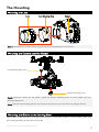
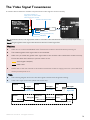
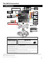
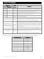
1
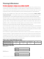
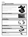
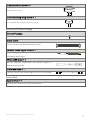
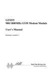
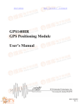
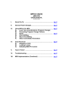
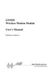
Zenmuse Z15-5D User Manual V1.04 2014.12 www.dji.com ©2013 DJI Innovations. All Rights Reserved. Warning & Disclaimer No further adjustment or changes are permitted to the Z15. The Z15 is specifically adjusted to support the Camera and Lens before leaving the factory. Please mount your camera directly to the Z15 when installing as no further adjustment or changes are necessary or permitted. Do not modify or add any other component/device (such as a filter, lens hood, etc.) to the camera; make sure to use the original battery; Failure to follow these guidelines may result in decreased performance or internal malfunction. The Z15 is only compatible with a flight control system specified by DJI Innovations (A2/Ace One/Ace WayPoint/WooKong M). To ensure highest stability and precision, download the corresponding assistant software and upgrade the flight control system MC firmware. Failure to do so may result in the Z15 working abnormally. Make sure the flight control system is operated in the safest possible environment when the main power battery is connected. We strongly recommend users remove all propellers, DO NOT use power supply from R/C system or flight pack battery, and keep children away during gimbal calibration and parameter setup. Please follow the guidelines in order to correctly mount and connect gimbal to your aircraft, as well as to install the assistant software on your computer. Please respect the AMA’s National Model Aircraft Safety Code. As DJI Innovations has no control over use, setup, final assembly, modification (including use of non-specified DJI parts i.e. motors, ESCs, propellers, etc.) or misuse, no liability shall be assumed nor accepted for any resulting damage or injury. By the act of use, setup or assembly, the user accepts all resulting liability. DJI assumes no liability for damage(s) or injuries incurred directly or indirectly from the use of this product. DJI and Zenmuse are registered trademarks of DJI Innovations Names of product, brand, etc., appearing in this manual are trademarks or registered trademarks of their respective owner companies. This product and manual are copyrighted by DJI Innovations with all rights reserved. No part of this product or manual shall be reproduced in any form without the prior written consent or authorization of DJI Innovations. No patent liability is assumed with respect to the use of the product or information contained herein. Firmware versions of supported DJI Flight control systems Flight control systems Firmware version of MC Ace One Ace WayPoint WooKong M A2 V4.02 V4.02 V5.26 V2.0 or above Specified Camera and Lens Type Z15-5D Mark II Camera Lens Canon 5D Mark II Canon EF 24mm f/2.8 IS USM Z15-5D Mark III Camera Lens Canon 5D Mark III Canon EF 24mm f/2.8 IS USM ©2013 DJI Innovations. All Rights Reserved. 2 Product Profile Z15 is an excellent gimbal designed for Aerial Photography. It has built-in slip rings within the mechanical structure, preventing the wire rod from entangling. The gimbal has an integrated independent IMU module, a special servos drive module, etc., which are dedicated to provide excellent performance in any working modes, including Orientation-locked control, Non orientation-locked control and FPV Mode (Reset). Working Mode Orientation-locked Mode Gimbal Point Gimbal point stays locked with aircraft nose direction FPV Mode Non orientation-locked Mode Gimbal point stays unchanged when aircraft nose direction changes. (Reset) Gimbal point stays the same as aircraft nose direction when powered up Gimbal and Gimbal point keeps the Relative angle between the Zero Aircraft Nose same relative angle with the gimbal point and aircraft nose between the gimbal point aircraft nose direction direction may change and aircraft nose Relative Angle TX Control Attitude stability Vibration Reduction Controlled Controlled Not controlled YES YES YES YES YES YES Command stick stands for gimbal rotation velocity, Stick Meaning Stick center position is for 0,its endpoint is maximum velocity. Command Linearity relative YES angle Command stick stands for gimbal rotation velocity,Stick center position is for 0,its —— endpoint is maximum velocity. YES —— Note1: ‘Gimbal point’ refers to the gimbal PAN rotation direction. Note2: ‘Attitude stability’ means the gimbal’s ROLL/TILT will not follow the aircraft’s ROLL/PITCH. Note3: ‘Gimbal rotating maximum velocity’ is corresponding to the TX 100% end-point. ©2013 DJI Innovations. All Rights Reserved. 3 In Box Gimbal & Gimbal Controller Unit (GCU) Gimbal × 1 The Z15 gimbal has built-in slip rings within the mechanical structure, which work to prevent the wire rod from entangling and enables rotational freedom for the 3 axes rotating rods. The gimbal has special built-in Z15 gimbal servo drive modules and independent IMU module. Gimbal Controller Unit (GCU) × 1 Connect the gimbal controller unit to the flight control system with a 5D CAN–Bus cable. The GCU will control the gimbal’s PAN, ROLL and TILT axes rotation. Main Parts Package Lens Retaining Ring × 1 For fixing the camera lens. Mounting Bracket × 4 For the gimbal and landing gear connection. Mounting Board for Receiver × 1 For fixing the GCU and providing the mounting position for the receiver or other device. Cable Clamp For tidying the cables on gimbal. ©2013 DJI Innovations. All Rights Reserved. 4 Camera Mount Screw × 1 For the camera mount. Lens Retaining Ring Screw × 1 For fixing the lens retaining ring to the gimbal. Screws and Cables Package Screws Package For mounting the gimbal to the aircraft (M2.5*8 Head-cup screw). 8-pin Cable Connect the GCU and Gimbal use the 8-pin cable. Gimbal Video Signal Cable × 1 For connecting the GCU and Wireless Video Transmission Unit, transmitting the AV signal. Micro-USB Cable × 1 For the parameter configurations and firmware upgrade via Assistant Software on PC. DJI The GCU communicates with the flight control unit via a CAN-Bus. DJI CAN-Bus Cable × 1 Spares Pack Spares Pack × 1 Damping units, Spare Screw, and Mounting Bracket. ©2013 DJI Innovations. All Rights Reserved. 5 Contents WARNING & DISCLAIMER ...............................................................................................2 PRODUCT PROFILE ..........................................................................................................3 IN BOX ............................................................................................................................4 CONTENTS ......................................................................................................................6 GIMBAL DESCRIPTION ....................................................................................................7 CAMERA SETUP ..............................................................................................................9 MOUNT ........................................................................................................................ 11 CAMERA WIRING/SHUTTER CONTROL ......................................................................... 13 VIDEO SIGNAL TRANSMISSION ..................................................................................... 14 GCU CONNECTION ........................................................................................................ 15 WORKING MODES/AUX2/AUX3 SWITCH SETUP ............................................................ 17 ASSISTANT SOFTWARE .................................................................................................. 18 TEST ............................................................................................................................. 18 APPENDIX ..................................................................................................................... 20 IMPORTANT NOTES...............................................................................................................20 PORT DESCRIPTION ..............................................................................................................21 GIMBAL LED INDICATOR .......................................................................................................21 TROUBLE SHOOTING ............................................................................................................22 SPECIFICATIONS ...................................................................................................................23 ©2013 DJI Innovations. All Rights Reserved. 6 The Gimbal Description Notes: Make sure nothing blocks the servo driver module rotation to avoid motor damage. Clear the obstacles at once if the rotating gimbal is blocked. No mechanical and electrical adjustment or change is permitted. Tips: Each servo driver module has two G8 ports, which are used to transmit servo and video signals. Z15-5D MARK II PAN 360° continuous rotation 8-pin Port To the G8 port of GCU 8-pin Cable Connect the GCU and Gimbal The Mounting Board for Receiver Servo Driver Module 1 Cable Clamp Damping Unit ROLL ±25° Servo Driver Module 3 TILT -120°~+15° Servo Driver Module 2 Gimbal status Indicator Lens Retaining Ring' s Screw IMU Module Lens Mount Position Video Transmission Cable To the A/V OUT port of 5D Mark II ©2013 DJI Innovations. All Rights Reserved. 7 Z15-5D MARK III PAN 360° continuous rotation 8-pin Port To the G8 port of GCU 8-pin Cable Connect the GCU and Gimbal The Mounting Board for Receiver Servo Driver Module 1 Cable Clamp Damping Unit ROLL ±25° Servo Driver Module 3 TILT -120°~+15° Servo Driver Module 2 Gimbal status Indicator Lens Retaining Ring's Screw IMU Module Lens Mount Position Video Transmission Cable To the A/V OUT/DIGITAL port of 5D Mark III ©2013 DJI Innovations. All Rights Reserved. 8 The Camera Setup Configure your camera by the following settings to meet the requirements of Z15 and make sure to read the related content according to your camera. Canon 5D Mark II Mode Dial Live View Turn the Mode Dial to set the shooting mode to Shutter-priority AE (Tv) or Manual exposure (M). Press down the Live View/shooting/Print/Share ( Press the AF.DRIVE button, select the drive mode as ) button. (10-sec.self-timer/Remote control) or (2-sec.self-timer/Remote control). Turn the Image Stabilizer switch, which is located on the lens, to OFF. It is recommended to adjust the shutter speed to within 1/100sec to 1/30sec. If shooting mode is set to Manual exposure, please adjust the aperture properly and set the ISO speed to A (Auto). Tips: In the Menu settings, the values in red italic font are strongly recommended. Failure to follow the recommended settings may results in shakey or poor footage/image quality. Canon 5D Mark III Mode Dial Movie Shooting Turn the Mode Dial to set the shooting mode to Shutter-priority AE (Tv) or Manual exposure (M). Turn the Live View shooting/Movie shooting switch ( Press the AF.DRIVE button and select the drive mode as ) to the Movie shooting position. (10-sec.self-timer/Remote control) or (2-sec.self-timer/Remote control). Turn the Image Stabilizer switch, located on the lens, to OFF. It is recommended to adjust the shutter speed within 1/100sec to 1/30sec. If shooting mode is Manual ©2013 DJI Innovations. All Rights Reserved. 9 exposure, please adjust the aperture properly and set the ISO speed to A (Auto). Tips: In the Menu settings, the values in red italic font are strongly recommended. Failure to follow the recommended settings may results in shakey or poor footage/image quality. The use of an SD card is preferred, as a CF card may effect the balance performance of the gimbal and lead to shakey or poor footage/image quality. ©2013 DJI Innovations. All Rights Reserved. 10 The Mounting Mounting the Lens Lens Lens Retaining Ring Camera Step 1: Mount the lens on the retaining ring first, before mounting the lens to the camera. Mounting the Camera onto the Gimbal Lens Retaining Ring Screw Camera Mounting Screw Step2: Mount the camera into the gimbal. Tighten the Camera Mounting Screw first then tighten the Lens Retaining Ring Screw. Note: Take care when pushing the lens into the lens mount position; too much force may damage the lens. Mounting the Gimbal to the Landing Gear Please adhere to the dimensions of the gimbal shown below to mount the gimbal to a proper Landing Gear using the mounting brackets (4) and M2.5*8 screws (8). ©2013 DJI Innovations. All Rights Reserved. 11 Ai rcr aft No se Mounting brackets and screws Landing Gear No se Camera and Gimbal Gi mb al X Y Z Step3: Attach the gimbal to the landing gear then tighten the thread locking screws. Notes: Ensure that the correct side of the servo driver module 1 faces the direction of the aircraft tail. Make sure the top and bottom plates of the dampening unit remain parallel when mounting in order to prevent the damping unit from being stretched or distorted. Keep overall balance when mounting, in order to ensure the center of gravity on the Z axis. The gimbal center of gravity has already been set, which directly determines the gimbal’s performance. Please do not adjust the gimbal center of gravity by yourself. The gimbal is a high-precision controlled instrument. Do not remove any screws in the gimbal. Doing so may result in decreased performance or even damage. Do not unplug any cables which are attached to the gimbal ports, or attempt to change or customize the mechanical structure. Make sure the cable connections are correct and secure to ensure the gimbal works normally and is in full control. ©2013 DJI Innovations. All Rights Reserved. 12 The Camera Wiring/Shutter Control The Camera Wiring Z15-5D gimbal can transfer the signal from transmitter to infrared signal for shutter control, please make sure you connect the camera with the Z15-5D gimbal correctly and the camera settings are correct. Step1: Connect the video transmission cable to the correct port on the camera. Z15-5D MARK II: To the A/V OUT port of 5D MARK II. Z15-5D MARK III: To the A/V OUT/DIGITAL port of 5D MARK III. Note: Make sure to press the AF.DRIVE button and set the drive mode as control) or (10-sec.self-timer/Remote (2-sec.self-timer/Remote control). The Shutter Control Z15-5D gimbal can transfer the signal from transmitter to infrared for shutter control, please set one 2-position switch/channel for remote shutter control. Make sure the shutter control module is correctly mounted and wired. Whichever selection of the switch on your transmitter was set; wire the right channel of the receiver to the SHUT port. One switch toggle corresponds to one photo shot. For example, toggle twice will result in two shot. Position – 1 Position – 2: First shot Position – 2 Position – 1: Second shot 2-Positon Switch 1 2 Tx Tips: The following diagram shows how the shutter control works. If the shutter control works abnormally, please check each step. RC Receiver TX TX Command 2-Position Switch Wireless 2-Position Switch Channel 3-Pins Cable GCU Camera TX Command SHUT Internal wire Infrared sensor Infrared shutter control command Wireless Camera Shutter ©2013 DJI Innovations. All Rights Reserved. 13 The Video Signal Transmission A wireless video transmission module is required for the video signal to access remotely. Connect to a battery to supply power for the wireless video transmission module + Gimbal Video Signal Cable Wireless Video Transmission Module Power Air End Video Signal Port Video Signal Disconnected GND Video Signal(Yellow:AV) GND(Black: ) Step1: Solder the Power/Video Signal/GND cables to a wireless video transmission module (Air End) respectively. Step2: Plug the gimbal video signal cable head into the GCU Video Signal Port. Notices: Make sure to connect the Wireless Video Transmission module to the GCU before powering on. The standard gimbal video signal cable is recommended. Make sure you solder the gimbal video signal cable to the wireless video transmission module correctly. Ensure the cables are insulated, to prevent a short circuit. Video Signal Cable(AV) GND Cable Please refer to the user manuals of the wireless transmitter module to supply power for it, since the GCU cannot provide power for it. Tips: The following diagram shows how the video signal transmits with the gimbal working. If the video signal access fails, please check each step. Camera GCU Gimbal AV signal AV signal AV Monitor AV input AV signal G8 Video transmission cable AV signal Gimbal Video Signal Cable 8-Pins cable Wireless video transmission module Ground end Wireless video transmission Wireless signal module 5.8G/2.4G/1.2G Air end Self-prepared by user ©2013 DJI Innovations. All Rights Reserved. 14 The GCU Connection The GCU Connection A2/WKM/ ACE ONE/ ACE Waypoint Micro-USB Port PC connection for configuration and firmware upgrades via a Micro-USB cable. Battery RC Receiver (Aircraft control) 2-Position Switch (4S~12S) 2-Position Switch 2-Position Switch 5D Wireless Video Transition Module Air End Heat Sinks AUX2 RUDD RC Receiver (JR) ELEV AILE 8-Channel Or 1 2 4 7 8-Channel RC Receiver (Futaba 2-Position Switch / Hitec) 2-Position Switch 2-Position Switch Or S-Bus S-Bus Receiver (Futaba) G8 Or Reserved & Disconnected Ensure the side with copper contacts is facing upward towards the heat sinks. PPM PPM Receiver CAN-Bus port of GCU For WKM/ACE ONE/ACE Waypoint, connect to any spare CAN-Bus port of the flight control system via a CAN-Bus cable. For A2, connect to the CAN2 or CAN1 port. Battery Make sure the battery voltage is in the required range of both the aircraft and the gimbal if you use only one battery for power supply. A2/WKM/ACE ONE/ACE Waypoint Refer to the A2/ WKM/ACE ONE/ ACE Waypoint User Manual for more connection and configuration details. Gimbal Controller (GCU) Make sure the ports are accessible when installing the GUC so as to facilitate wiring and software configuration. In 3-pin ports, pins near the nicks are the signal pins. DO NOT cover the heat sinks, keep them unobstructed. The GCU module is NOT water-proof or oil-proof. Transmitter and Receiver Above are example connections, which require two transmitters and two receivers. One transmitter and receiver are used for gimbal control and the other are used for aircraft control. Users can also use a transmitter and a receiver to control both the gimbal and aircraft. Configure the Aileron, Elevator, Rudder channels on the transmitter for gimbal control. Command stick stands for the gimbal rotation velocity,the center position is for 0 and the endpoint for maximum velocity (both clockwise and counter clockwise directions). (End Point is 100%) Choose one 3-position switch/channel as the Z15 working modes switch.(MODE) Choose one 2- position switch/channel as the camera shutter control switch(SHUT), one for the camera lens orientation switch in Reset Mode (AUX2). Please refer to the A2/ WKM/ACE ONE/ACE Waypoint User Manual for aircraft control setting. Connect the receiver to GCU correctly. * When using with A2 latest firmware version 2.5, all of the gimbal channels can be setup through the A2 receiver. Refer to A2 User Manual for details. ©2013 DJI Innovations. All Rights Reserved. 15 The GCU Ports Description The following table shows the GCU channels and the TX channels connection. TX Channels GCU Descriptions JR Futaba/Hitec Channels AILE 1 ROLL For roll axis control (left/right). The velocity is zero if disconnected. ELEV 2 TILT For tilt axis control. The velocity is zero if disconnected. RUDD 4 PAN For pan axis control. The v is zero if disconnected. AUX2 7 MODE 2-position switch channel For Working Mode switch. For camera shutter control (both taking picture and recording video SHUT are available). It is off when non-connection and disconnected. When the AUX2 is connected to a 2-position switch channel, it is used 2-position switch channel Or Futaba S-Bus channel for camera orientation (downward or forward) switch in FPV Mode AUX2 (Reset). The camera orientation is set to forward while non-connection or disconnected. If a S-Bus receiver is used, it should be connected to the AUX2 port. When the AUX3 port is connected to a 2-position switch channel, it is PPM channel AUX3 used for the Z15-5D video recording control. If a PPM receiver is used, it should be connected to the AUX3 port. The following table shows the corresponding relationship between the GCU and the S-Bus/PPM channels. S-Bus/PPM Channels GCU Channel 1 ROLL 2 TILT 4 PAN 7 MODE 5 SHUT 8 AUX1 9 AUX2 6 AUX3 ©2013 DJI Innovations. All Rights Reserved. 16 The Working Modes/AUX2/AUX3 Switch Setup Setting the Gimbal Working Mode Switch Whichever 3-position switch you select as the working mode switch, wire the right channel of receiver to MODE port. At each switch position, use end-point fine tuning to set the AUX2 channel of JR/7 channel of Futaba/Hitec for the three Working modes. Orientation-locked Mode Back to center FPV Mode (Reset) MODE channel end-point 60%~90% Non orientation-locked Mode MODE channel end-point 60%~90% Notes: The gimbal will work in Orientation-locked Mode, if there is no connection to the MODE port. Gimbal default works in FPV Mode after power on. The gimbal will maintain the Working Mode from the last moment if the cable between the MODE port and the Receiver is disconnected while powered on. Tips: For the 3-position switch, you may assign: Position-1 to Non orientation-locked 3-Position Switch Position-2 to FPV Mode (Reset) 1 2 3 Tx Position-3 to Orientation-locked Position-1 and Position-3 can be reverse assigned. One 2-position switch can be assigned for any two of the working modes as you like. Setting the AUX2 Switch The Z15 supports controlling the camera lens downward or forward in Reset Mode. Please wire the right channel of receiver to the AUX2 port. You may assign: Position-1 to DOWNWARD; Position-2 to FORWARD; or reverse the assignment. 2-position switch 1 2 Tx Notices: This function can only work in FPV Mode (Reset). When this function is enabled, if the working mode switches from the other modes to the FPV Mode (Reset), the gimbal will force the camera lens to face forward or downward depending on AUX2 Switch. The camera orientation is forward while non-connection or disconnected. Tips: When the AUX2 port is connected to the Futaba S-Bus channel it is used as the S-Bus channel input. ©2013 DJI Innovations. All Rights Reserved. 17 Setting the AUX3 Switch The Z15-5D supports camera video recording. Please wire the right channel of receiver to AUX3 port. Every toggle is set for start/stop recording. The Assistant Software Installation and Usage Step1: Make sure the driver is installed correctly and has been installed beforehand if you use A2, WKM, ACE ONE or ACE WAYPOINT. Step2: Please download the assistant software installer from the DJI Innovations website. Step3: Double click the assistant software installer file and follow the steps to finish installation. Step4: Run the assistant software. Step5: Please upgrade the firmware and configure the parameters according to the assistant software indications if necessary. Test Check List Before Flight Notes: The gimbal is installed firmly to the landing gear, and the camera is mounted correctly and stably. All cables are correctly connected, without any connected back to front. The gimbal video signal cable is in good soldered condition if wireless video transmission module used. Correct connection between the GCU and RC receiver. Normal connection between the GCU and flight control system. Correct camera setup. Correct Transmitter settings. The firmware of flight control system has been upgraded to the latest version. Tips: Please turn to the Trouble Shooting section in Appendix if an abnormal situation occurs. ©2013 DJI Innovations. All Rights Reserved. 18 Flight Test Step1: Ensure the batteries are fully charged for the transmitter, GCU and all the other devices on your aircraft. Step2: Make sure all connections and wirings are in good condition. Step3: Toggle on the switch. Step4: Make sure to adjust the Roll axis of the gimbal to be level. Step5: Power on the gimbal and wait for self-testing to begin. The Roll axis will rotate first, and then the yaw and pitch axes will rotate quickly at the same time. Step6: After self-testing, the camera lens will point to the aircraft nose direction and the three axes of the gimbal should be in the condition as the above diagram shows. Step7: The gimbal will enter initialization, at this time the three axes will rotate very slowly. Step8: The gimbal is at a standstill after initialization and ready for use. Step9: Toggle the Working Modes switch on your transmitter, making sure it is working properly. Step10: Toggle the Working Modes to the Non orientation-locked, FPV Mode (Reset), Orientation-locked respectively, and then try to push your sticks lightly in Roll, Tilt and Pan modes to see if your gimbal moves to the corresponding direction. If not, return to the ‘Setting the Working Mode Switch’ section to correct your settings. Note: If the gimbal is abnormal after initialization, please refer to the Trouble Shooting in Appendix. ©2013 DJI Innovations. All Rights Reserved. 19 Appendix Important Notes For safety reasons, please pay serious attention to all following items: Ensure nothing blocks the servo driver module rotation, to avoid motor damage. Before powering on, spin the gimbal by hand through the complete rotational axes to ensure nothing is blocking the mechanical movement of the gimbal. Ensure that the side of the servo driver module 1 with ports correctly points towards the aircraft tail direction. The gimbal center of gravity has been set, which directly determines the gimbal’s performance. Please do not adjust the gimbal center of gravity by yourself. The gimbal is a high-precision controlled instrument. Do not remove any screws in the gimbal. Doing so may result in decreased performance or even damage. Do not unplug any cables which are attached to the gimbal ports, or attempt to change or customize the mechanical structure. Make sure the cable connections are correct and secure to ensure the gimbal works normally and is in full control. Make sure to connect the Wireless Video Transmission module to the gimbal controller before powering on the system. The factory gimbal video signal cable is recommended. Make sure you solder the gimbal video signal cable to the wireless video transmission module correctly. And ensure the cables are insulated, to prevent a short circuit. Make sure the current consumption of wireless video transmission module does not exceed 1A, to prevent the GCU from damage. Keep the gimbal away from any power cables; otherwise it may lead to a short circuit of the gimbal. Make sure to adjust the Roll axis of the gimbal to be level before powering on. ©2013 DJI Innovations. All Rights Reserved. 20 The Port Description The GCU ROLL For roll axis control TITL For tilt axis control PAN For pan axis control MODE For Working Mode select SHUT For camera shutter control AUX2 For gimbal orientation (downward or forward) switch in FPV Mode; S-Bus Receiver AUX3 For the video recording control; PPM Receiver To the wireless video transmission module, transmitting the AV signal XT60 To the battery G8 To the gimbal, transmitting video signal Micro-USB port: PC connection for configuration and firmware upgrades CAN-Bus port: Use CAN-Bus to connect the GCU to the flight control system The Gimbal Video Transmission cable port 8-Pin Cable Port To the AV port of Camera To the G8 port of GCU The Gimbal LED Indicator LED Indicator Description The gimbal works normally Some servo is recovering from overcurrent protection The gimbal is performing a self-check The GCU is disconnected from the Flight control system ©2013 DJI Innovations. All Rights Reserved. 21 Trouble Shooting NO. 1 2 What Why (1) Too much TX trim (1) Adjust the TX trims (2) The GCU and flight control (2) Connect the GCU and flight The gimbal keeps drifting system is disconnected control system after initializing (3) The Z15 mounting (3) Ensure the Z15 mounting direction is not aligned to the direction is aligned with the aircraft nose aircraft nose The gimbal is abnormal Abnormal calibration after Please contact the local dealer or after initializing manufacture DJI Innovations customer service Cannot distinguish the 3 How to gimbal direction when in BVR flight use Switch to the FPV Mode first, then to another Working Mode needed (1) The wireless video transmission unit has been 4 The gimbal green LED is on disconnected but without video display (2) Wrong power supply for (1) Check the wireless video transmission unit connection wireless video transmission unit ©2013 DJI Innovations. All Rights Reserved. 22 Specifications General Built-In Functions Three Working Modes Orientation-locked control Non orientation-locked control FPV mode (Reset) Built-in independent IMU module DJI gimbal special servos drive module Wireless video transmission supported Camera shutter control supported Wide range voltage input supported S-Bus/PPM Receiver supported Peripheral Supported Camera CANON EOS 5D MARK II; CANON EOS 5D MARK III Current Supported Lens CANON EF 24mm f/2.8 IS USM GCU Input Power 4S~12S LiPo Battery Control Requirement Four spare receiver channels at least Assistant Software System Requirement Windows XP SP3; Windows 7; Windows 8(32 or 64 bit) Mechanical& Electrical Characteristics Working Current Static current: 200mA (@25V) Dynamic current: 400mA (@25V) Locked-rotor current: 4A (@25V) Operating Temperature -10°C ~ 50°C Weight 1.42Kg Dimensions 204mm × 242mm × 264mm GCU Weight 63g GCU Dimensions 64.2 mm × 34.1mm × 19.5mm Working Performance Load Weight (Reference Value) 2615g(5D MARK II with SD Card & Battery & CANON EF 24mm f/2.8 IS USM Lens) 2664g(5D MARK III with SD Card & Battery & CANON EF 24mm f/2.8 IS USM Lens) Controlled Angle Accuracy ±0.02° Maximum Controlled Rotation Speed Pan axis:±±90°/s ©2013 DJI Innovations. All Rights Reserved. 23 Tilt axis:±±130°/s Roll axis:±±30°/s Controlled Rotation Range Pan axis control: ±360° continuous rotation Tilt axis control: ±From -120° to +15° Roll axis control:±±25° ©2013 DJI Innovations. All Rights Reserved. 24