1
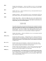
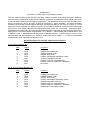
TRANSTERM 5
USERS MANUAL
COMPUTERWISE.
TRANSTERM 5
USERS MANUAL
Copyright 1997-1999
(All rights reserved)
Specifications and information
subject to change without notice.
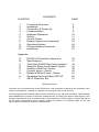
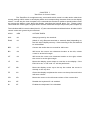
CONTENTS
CHAPTER
PAGE
1
2
3
4
5
6
7
8
9
10
11
4
6
7
8
10
11
18
20
24
26
27
Functional Overview
Installation
Connection & Power Up
Communication
Keyboard Operation
Set-Up
Control Codes
Escape Sequence Commands
Operating Modes
Communications Protocols
Interfacing
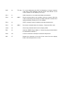
Appendix
A
B
C
D
E
F
G
H
I
EIA RS-232 Interface Signal List
Specifications
TransTerm 5A/B/C Bar Code Interface
Magnetic Stripe Card Reader Option
Auxiliary Serial Port Option
Counter Inputs - Option
Relays & Relay Drivers - Option
Re-setting Factory Default SETUP
ASCII Character Set
30
31
33
36
38
42
44
46
47
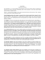
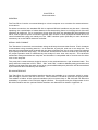
INTRODUCTION
To ensure your successful use of the TransTerm 5, this handbook contains all the necessary information for installation, interfacing, operation and programming of the terminal.
This manual presents material relevant to the TransTerm 5, 5A, 5B, and 5Cmodels. Most features
and capabilities are common to all three models with the TT5 being the basic model and the TT5A
having enhancements over and above that of the 5 primarily in the I/O options, and the 5B and 5C
are for those configurations which support multiple I/O options. As of March 1998, the 5C has
superceded the 5B which has been discontinued.
CHAPTER 1
Functional Overview
The TransTerm 5 is a self-contained keyboard/display data entry terminal which is designed to
transmit and receive information interactively with a host computer or with some other similar
communications capable device.
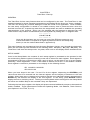
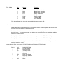
Figure 1-1 presents block diagram of the major functional elements of the terminal. Each element
of the terminal will be briefly described here.
The keyboard is used by the operator to input character codes for transmission to the host computer or, depending upon the mode of operation, for local presentation on the display or local
terminal functions. The keyboard is a 24 key sealed membrane switch array with an embossed
graphic overlay. Each valid keystroke will be accompanied by an audible “click” sound for positive
operator feedback.
The display is a two line by twenty-four (48) character electro-reflective liquid crystal display. It
can display any of the 96 standard ASCII characters in a 5 x 7 dot matrix font and has a blinking
cursor symbol to indicate current character placement. The display has as its primary purpose to
visually present to the operator all valid displayable ASCII codes which are received via the Communication port, or are operator entered in Modes 2 and 3. The display is also used to present the
terminal setup parameter values to the operator in the setup Mode. A display backlight option is
available (a different display module) that incorporates an electroluminescent (electro-chemical)
lighting element behind the liquid crystal display. It is preferable to order the TransTerm 5 with the
backlight option rather than to add the option after the original purchase.
The communication port serves as the interface between the TransTerm 5 and the computer (by
direct connection or via a modem). The communication port takes data entered from the keyboard
(in Mode 1) or data in the display memory and transmits it in serial asynchronous format at the
selected baud rate and character parity. The communication port also de-serializes received data
and places it in the input buffer. The standard communication port has an RS-232 serial interface
on a DB-25F connector. The port can be optionally equipped with the RS-422 compatible TNET
interface for networking applications. The TNET interface signals are available on the standard
DB25F connector or the optional RJ45 modular jacks (not available on the TT5-xx models).
The input buffer is a 100 (16 characters on the TT5-xx models) character first-in/first-out (FIFO)
memory used to temporarily hold data which has been received by the communications port. The
received data is subsequently removed from the input buffer and routed to the display buffer or
operated upon as in the case for ASCII control codes and ESCape commands.
The barcode interface option (Not available on the TT5-xx models) is a built-in interface for a
wand barcode scanner or other types of wand emulating scanners, including CCD or laser scanners which posses which will auto-discriminately decode bar code symbols in any one of several
symbologies (Code 39, Code 128, Interleaved 2of5, UPC/EAN and CODABAR). The decoded
data will be placed on the display screen at the cursor position and/or transmitted out the serial I/
O port, depending on the operating mode and setup configuration.
The magnetic stripe reader interface option (not available on the basic TT5-xx models) is an
integral input interface for the MT-211 magnetic stripe card reader. It is capable of interfacing to a
track 2 reader or a track 1 reader on the TT5A model, or a dual track (1 and 2) reader on the TT5B/
C models. The data read from the card is translated to ASCII characters and transferred to the
display buffer at the cursor position and/or transmitted out the serial I/O port (depending on the
operating mode and the setup configuration).
The auxiliary serial I/O port option (not available on the basic TT5-xx models) is a built-in interface which supports unidirectional serial communications, at a user selectable baud rate with
another RS-232 compatible device.
The TT5A/B/C models can also be equipped with the Pulse Output option and Quad Counter Input
option. The TT5B/C models can be equipped with the enhanced auxiliary serial port, the Dual or
Quad relay output module, Touch Key Reader Input Option, and Weigand Input Option (some
restrictions may apply, please consult the factory about option compatibility).
CHAPTER 2
Installation
GENERAL
This chapter contains information related to the unpacking and installing of the Transterm 5 terminal. The installation procedure includes power application, hookup and power-up checkout procedures.
UNPACKING
The Transterm 5 is packed in a reinforced cardboard carton containing the following items:
TransTerm 5 terminal
AC power adapter
Operator’s Manual
Other Optional Accessories
Remove each of the above mentioned items from the box and inspect each item and the box itself
for physical damage. Notify the shipper and selling agent immediately of any damage.
*********
WARNING
*********
Subjecting the Liquid Crystal Display to temperatures above 70 C or below 20 C for extended periods of time could permanently damage the display.
The Transterm 5 is designed to either set on a horizontal surface such as a desk or work bench
(consider the optional “tilt base” for this situation), or to be mounted on a vertical surface (consider
using the “tilt bracket” for this situation). There is also a new enclosure specifically designed for
wall-mounted applications which has in integral two-piece mounting bracket. You should refer to
the instruction leaflet which accompanies that enclosure for its specific mounting procedure. For
built-in O.E.M. applications, the terminal can be removed from its standard enclosure and panel
mounted behind an appropriately sized cutout using the optionally available bezel kit.
CHAPTER 3
Connection and Power-up
CONNECTION
Depending on your installation requirements (see Chapter 10), connect the cable from your computer or modem to the TransTerm 5 I/O connector (DB-25F) (See Figure 3-1). Next insert the
power plug from the wall plug-in power adapter into the jack next to the I/O connector. Plug the
power adapter into a nearby 120 VAC outlet. Power is now applied to the unit.
NOTE
The TransTerm 5 has no fuse or power on/off switch. Within one second,
three loud beeps will be heard to indicate that a successful power-up reset
has occurred and that the unit is ready for operation. If more than three
beeps are announced, the terminal is making an exceptional power-on sequence due to there being invalid setup data in the EEPROM.
POWER-UP AND CHECKOUT
Perform the following procedure to power-up and checkout your terminal.
1. Apply power to the unit by inserting the AC power adapter’s miniature phone plug into
the terminal’s power jack. The terminal will report a successful power-up sequence on
the display in the following manner:
“TRANSTERM 5x C199x
TT5x Ver x.xx”
2. After a successful power-up, configure the desired set-up features as described in
Chapter 6. This would include the adjustment of the display contrast for the viewing
angle best suited for the installation situation. The contrast on the TT5B and TT5C can
only be adjusted by opening the terminal’s enclosure to access a screwdriver potentiometer.
3. The new or modified set-up features will be programmed into the terminal’s nonvolatile memory.
CHAPTER 4
Communication
GENERAL
The TransTerm 5 can be connected directly to a local computer or to a modem for remote telecommunications.
For direct connection, the standard RS-232 or optional RS-422 interfaces may be used. Generally
speaking, the consideration of cable distance is the determining factor in choosing which of the two
interfaces is preferred. For a connection of less than fifty feet, the standard RS-232 interface will
serve, and for point-to-point connections greater than 50 feet or when multiple terminals are to be
communicated with using one serial port, the TNET interface option (RS-422) on each terminal is
necessary as is the TIM1B network controller.
SERIAL DATA FORMAT
The Transterm 5x terminal communicates using serial asynchronous data format. Each character
is transmitted using a leading start bit, 7 or 8 data bits, a parity bit, and one or two stop bits. The
data bits are transmitted and received with the least significant bit first in time sequence followed
by the parity bit and the stop bit(s). The terminal’s serial receiver needs to receive only one stop bit
for proper operation and is unaffected by the receipt of more than one stop bit. The terminal’s
transmitter always transmits two stop bits and therefore is compatible with a receiver set for either
one or two stop bits.
The parity bit is used to detect single bit errors in the received data on a per character basis. The
parity selection setup bits in SR1; “PEN”, “PS1” and “PS2”, enable or disable parity generation and
checking and determine the state of the parity (even/odd/mark/space) bit which will be transmitted
by the terminal and checked by the receiver.
RS-232 INTERFACE
The TransTerm 5x communication interface signals are available on a connector which is accessible through a cutout in the rear of the unit. The connector is a DB-25 (EIA RS-232 type) female.
The addition of either of the optional interfaces (20 ma current loop or RS-422) will not affect the
availability or operation of the RS-232 signal interface. The signals and pin assignments for the
RS-232 interface and the optional RS422 interface are described in detail in Appendix A.
LOCAL KEYBOARD ECHO
In a typical Mode 1 installation, the TransTerm 5x will transmit and receive data simultaneously.
Data entered on the keyboard will be transmitted out the communications port; however, with local
echo enabled (LKE), the keyed data is also presented locally on the display in addition to being
transmitted.
CHAPTER 5
Keyboard Operation
The TransTerm 5 keyboard delivers operator keyed input to the terminal. In so doing it generates
ASCII codes that, depending on the Mode of operation, are either transmitted out the communications port or processed and/or displayed internally within the terminal.
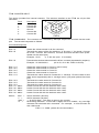
The TransTerm 5 keyboard (See Figure 5-1) is a flat panel membrane keyswitch array organized in
a six column by four row array of key elements located on 0.750 inch center-to-center placement.
The array is covered by a laminated five-color graphic overlay which also includes a clear window
covering the display. The twenty-two main keys on the TransTerm 5 keyboard can generate codes
in each of three different manners, by singular depression of the key or by preceding the key
depression with a single depression of either the S1 (Red) or S2(Blue) shift keys. For custom
applications, the standard 5-color overlay can be replaced by (at the time of order) a window
overlay which then allows the purchaser to customize the keyboard legends easily.
Unshifted keys include the nine numerics (0-9), Clear, Delete, Enter, Space and the eight function keys F1 through F8 inclusive. The numeric keys generate the ASCII numeric codes in the
range of Hex 30-39. The Clear, Delete, Enter and Space keys generate Hex 18, 7F, OD and 20
respectively. The eight function keys can generate up to fourteen characters of ASCII data (only
two codes in the TT5-xx model) depending on how they are programmed by the user. The character codes so generated may be regular displayable ASCII or can be control codes (such as the
ENTER code) or an escape sequence which will be transmitted or internally interpreted accordingly depending on the current operating mode of the terminal, or a mixture of all of these.
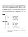
Shifted keys are generated with a two-key-stroke sequence which begins with either the Red “S1”
key or the Blue “S2” key. The codes which can be keyed with these two shift keys are as follows:
Shift Key
Codes
S1 Red
ACEGIKMOQS
U W Y “( % = . - * ESC
S2 Blue
BDFHJLNPRT
V X Z ‘ ) $ @ ? + / HEX
CHAPTER 6
TransTerm 5 Set-Up
GENERAL
The TransTerm 5x has many features that can be configured by the user. The TransTerm 5x has
standard settings for these operating parameters pre-initialized at the factory as “factory defaults”.
The user can change any of these settings to meet the needs of his application. Once modified,
the new setup configuration is saved in non-volatile memory that is preserved even when the
terminal is turned off. At power-up reset time, the setup values are used to establish the operating
characteristics of the terminal. When you are satisfied with the features as selected you may
inhibit further setup feature modifications from the keyboard by setting Bit 7 in Register SR3.
**********
C A UT I O N
**********
Once this bit has been set you must use one of the ESCape sequence commands described in Chapter 8 to regain keyboard access to the Setup Registers (or use the method described in Appendix H).
The setup features are programmed into the setup Registers via key entry through the keyboard.
When the two shift keys are actuated in the following order, S2 (blue) - S1 (red) - S2 (blue), the
TransTerm 5 will enter the setup mode. Any data, which was on the display will be erased and lost.
SETUP MODE
Once in the Setup Mode, the contents of each setup register is presented to the operator for his/
her review along with the option of entering a new set of values into each register. Each register is
represented in the form of eight binary digits, each of which, can be either a one or a zero setting.
Generally, where applicable, a one ‘1’ will enable a feature and a zero ‘0’ will disable a feature.
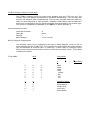
Each register’s contents is presented on the display in the following format:
SR 12345678 12345678
SR1 00101100
When you have keyed in the new “1”s and “0”s for the register, depressing the ENTERkey will
cause those bits to be entered into the internal register and the display to advance to the next
register. When there are no changes to be made to the bits in an individual register, depressing the
ENTER key will advance the display to the next register. To exit Setup, press ENTER until the
display returns to a blinking cursor. The keys on the keyboard which are illegal for the Setup Mode
will cause an Audible Beep to be sounded if they are depressed.
Following the last setup register, the display will present several additional prompts to be examined
and/or modified. These parameters include the Operating Mode, Unit Address, Total Columns,
(and Options in the TT5A ,B, or C).
SUMMARY OF SET-UP FEATURES
Set-Up
Register
Bit
No.
Name
1
1
1
1
1
1
1
1
1
2
3
4
5
6
7
8
BR1
BR2
BR3
PS1
PS2
PEN
DBS
CSE
Baud Rate Selection
Baud Rate Selection
Baud Rate Selection
Parity Selection
Parity Selection
Parity Enable
7/8 Data Bits
CTS Enable
2
2
2
2
2
2
2
2
1
2
3
4
5
6
7
8
EKR
LKE
ELW
ENL
ELM
XAL
AKE
EXP
Enable Key Repeat
Enable Local Echo
Enable Line Wrap
Enable New Line
Enable Line Mode
Send All Data
Auto Kbd Re-enable
Enable Xon/Xoff
3
3
3
3
3
3
3
3
1
2
3
4
5
6
7
8
DKB
DBT
DSK
DRS
DES
DHX
DSM
DRM
A/B/C
B/C
A/B/C
Disable Keyboard
Disable Backlight Timeout
Disable Shift keys
Disable Reset Msgs
Disable ‘ESC’ Key
Disable ‘HEX’ Key
Disable ‘SETUP’ Mode
Disable ‘RESET’ Mode
4
1-8
—-
A/B/C
See Appendices
5
1-8
—-
A/B/C
See Appendices
6
1-8
—-
B/C
See Appendices
7
7
7
7
1
2
3
8
ETM
WEN
WFC
EHM
B/C
C
C
5B
Enable Touch Memory
Enable Weigand Reader Input
Enable Weigand Facility Code
Enable Display Hide Mode
8
8
1-4
5-8
ECL
ECH
B/C
B/C
Enable Counter Input Low Detect
Enable Counter Input High Detect
Model
Function
A/B/C - Setup bit for TT5A, B, and C models only.
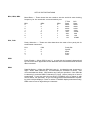
SET-UP BIT DEFINITIONS
BR1, BR2, BR3
Baud Rate — These three bits are used to set the serial bit rate clocking
frequency for the terminal’s communications port.
TT5/A
B/C
BR1
BR2
BR3
Rate
Rate
0
0
0
9600
9600
1
0
0
4800
4800
0
1
0
2400
2400
1
1
0
1200
1200
0
0
1
600
19200
1
0
1
300
300
0
1
1
150
150
1
1
1
110
57600
PS1, PS2
Parity Selection — These two bits determine the state of the parity bit for
transmitted characters.
PS1
0
1
0
1
PS2
0
0
1
1
Parity Bit
Space
Mark
Even
Odd
PEN
Parity Enable — When PEN is set (1), a parity bit who’s state is determined
by PS1 and PS2 is appended to the data bits of the transmitted and received
data character.
DBS
Data Bit Select — When the DBS bit is set (1), the data bits per character is
eight. When DBS cleared (0), the data bits per character is seven. This
count excludes the Start, Stop and/or any Parity bit specified. If the PEN bit
is cleared (0), and the DBS is cleared (0) (7 bits), then a parity bit of zero is
transmitted. If you are using the terminal (TT5A/B/C only) in Mode 3 with
UAC’s above 127 (decimal), or you are using the broadcast address capability (UAC=255)to display a “clock” on all the TT5A/B/C displays simultaneously,
DBS must be set to eight bits per character.
CSE
CTS Enable — When the CSE bit is set (1), the TransTerm 5 logic will sense
the state of the CTS signal (RS-232 pin 5) before it transmits data out the
communication port. If CTS is false, the transmission will not commence and
will be held off until the CTS signal returns to a true state. When the CSE bit
is cleared (0), the state of the CTS signal is ignored by the terminal.
EKR
Enable Key Repeat — When EKR is set (1), and a keyboard key is pressed
for more than one half a second, the keyboard will generate the same key
code repeatedly at a rate of eleven per second until the key is released.
LKE
Local Keyboard Echo — When LKE is set (1), data generated by keyboard
entry in addition to being transmitted out the communications port is internally echoed back to the terminal input for effective half-duplex operation.
ELW
Enable Line Wrap — Whenever ELW is cleared (0), and the cursor is on the
last character location of the line, the next character placed on the display
will overwrite the last character on the current line. If ELW is set (1), and the
cursor is on the last character location of the line, the next character will
cause the cursor to move to the next line and that character to be placed in
the left-most position of the new line. If the cursor is on the bottom line of the
display at this occurrence, then the display will scroll up one line unless
scrolling is disabled by ELM being cleared (0).
ENL
Enable New Line — When ENL is set (1), it will cause “LF” codes received by
the terminal to be interpreted as a “CR” and “LF”. When ENL is cleared (0),
the ENTER key will generate a “CR” in Mode 1 and when ENL is set (1), the
ENTER key will generate a “CR” and “LF” in Mode 1. If LKE and ENL are
both set (1) in Mode 1, then a “CR” will be locally echoed and a “CR” and “LF”
will be transmitted.
ELM
Enable Line Mode — When the ELM bit is cleared (0), the display buffer is
organized as a fixed page and scrolling is inhibited. The cursor will not advance beyond the last line of the display nor will the top line be lost due to
scrolling. In addition, in Modes 2 and 3, when ELM is cleared (0), all keyed
data in the display buffer is transmitted when the ENTER key is depressed,
and when ELM is set (1), only keyed data on the current line (cursor location) will be transmitted (See XAL bit for additional permutations).
XAL
Send All Data — When the XAL bit is set (1), in Modes 2 and 3 the terminal
will transmit all of the data in the display buffer at the time the ENTER key is
depressed. When the XAL bit is cleared (0), only the key-entered data in the
display buffer is transmitted.
AKE
Auto Keyboard Re-enable — When the AKE bit is set (1) in Mode 2, the
terminal will automatically have its keyboard re-enabled after completing transmission of the data for the previous ENTER operation. When the AKE bit is
cleared (0), the terminal’s keyboard will remain disabled until it has received
an ASCII SI code.
EXP
Enable Xon/Xoff Protocol — When the EXP bit is set (1), the terminal will
transmit the ASCII XOFF (Hex 13) code whenever the input buffer is full.
When the input buffer is again empty the XON (Hex 11) code is transmitted.
When the EXP bit is cleared (0), this procedure is disabled.
DKB (A/B/C)
Disable Keyboard — When DKB is set (1), keyboard input will be inhibited.
Input from optional interfaces will be permitted. This is normally set and
cleared under program control to temporarily accept data solely from the
optional input device (TT5A/B/C only).
DBT (B/C)
Disable Backlight Timeout — When DBT is set (1), the backlight for the LC
display remains on. When DBT is cleared (0), the display backlight turns off
after *** minutes of idle time.
DSK
Disable Shift Keys — When DSK is set (1), the S1 and S2 shift keys are
inhibited. This is used primarily to disable the alpha shift inputs from the
keyboard. WARNING - Setting this bit will lock the user out of the setup
mode.
DRS
Disable Reset Messages — When the DRS bit is set (1), the messages
presented on the display during the power-up reset sequence will be inhibited.
DES
Disable “ESC” Key — When the DES bit is set (1), the keyboard ESC key (S1
space) entry has no affect.
DHX
Disable Hex Mode — When the DHX bit is set (1), the keyboard’s “HEX” key
(S2 SPACE) used to enter hexadecimal character code values is defeated.
DSM
Disable Setup Mode — When the DSM bit is set (1), the operator will no
longer be able to gain access to the SETUP Mode from the keyboard of the
TransTerm 5. You are in effect locked out of the SETUP mode and can no
longer modify any of the SETUP registers.
***********
C A UT I O N
***********
To re-gain such access, the terminal would have to be connected to another
RS-232 compatible ASCII device and the appropriate ESCape Command
(See CSB in Chapter 8) would have to be transmitted to the terminal from the
attached device to clear the DSM bit and regain keyboard access to the
SETUP Mode. If the user is unable to clear the DSM bit remotely, then the
user will have to perform one of the procedures outlined in Appendix H.
DRM
Disable Reset Mode — When the DRM bit is set (1), the keyboard entered
reset sequence is defeated.
ETM (A/B/C)
Enable Touch Memory Option — When ETM is set (1), and the TransTerm is
equipped with the Touch Memory Interface Option, the TransTerm will read
Touch memories (coin sized stainless steel cans that are pre-encoded with
hexidecimal characters). Touch memories are more durable than barcodes
or MSCR cards.
ECL (B/C)
Enable Counter Input Low Detection – Each of the four ECL bits, when
set to a one will cause the respective counter input to increment its value
upon detecting a high-to-low transition of its input state.
ECH (B/C)
Enable Counter Input High Detection – Each of the four ECH bits, when set
to a one (1) will cause the respective counter to increment its value upon
detecting a low-to-high transition of its input state.
EHM (B/C)
Enable Hide Mode — When EHM is set (1), the LCD does not display operator entered characters. The LCD displays a special symbol for each key
entry to “Mask” the actual data entered. This is for security applications
where scanned/keyed codes/passwords are to be protected. EHM is available in Operating Modes 2 & 3.
OPERATING MODE — Enter a value of 1, 2 or 3 (See Chapter 9).
CONTRAST — Enter a value from 1 to 7 followed by the ENTER key and observe display from a
comfortable viewing angle for the best contrast. Repeat until satisfactory. Press ENTER to continue.
UNIT ADDRESS — Enter a “UAC” value from 001 to 250 for the Mode 3 address.
TOTAL COLUMNS — Enter a value of 24. (A value of greater than 24 for the TransTerm 5 or 5A will
create extra bytes of hidden data storage into which key-entered data can be stored unseen by the
terminal operator. This facility might typically be used to key in a hidden password, etc.
OPTIONS — (Not for TT5-xx) Enter a numeric value which will be interpreted by the particular
option installed in the TT5A/B/C (bar code interface option, magnetic stripe card reader interface,
auxiliary serial port option).
CHAPTER 7
TransTerm 5 Control Codes
The TransTerm 5 recognizes many commands which cause it to take action other than
merely placing ASCII codes in the display buffer and corresponding character fonts on the display
screen. In this way the host computer can command the terminal to perform special actions such
as moving the display cursor about the display, sounding the internal alarm, etc. These control
commands are of two types, singular ASCII control codes and Escape sequences (see Chapter 8).
The individual ASCII control codes (Hex 01-1F) are summarized and defined below. All other ASCII
control codes are ignored by the terminal.
ASCII
HEX
ACTION TAKEN
NUL
00
Always ignored by the terminal.
ENQ
05
(Mode 3 only) Request terminal to transmit data (depending on
the XAL bit) in display memory. If the enter flag is set, the data will
be transmitted.
BEL
07
Causes the audio alarm to sound for 250 msec.
BS
08
Will move the cursor one character location to the left, unless
cursor is at the left margin.
HT
09
Will move the cursor one character location to the right, unless
the cursor is at the right margin.
LF
0A
Moves the display cursor down to next line on the display. If the
ENL bit is set, a “CR” and “LF” will be performed.
VT
0B
Move the display cursor up to the top line unless the cursor is
already on the top line.
FF
0C
Clears the display and places the cursor on the top line and in the
left-most column.
CR
0D
Moves the cursor to the left-most column of the current line.
SO
0E
Disable the keyboard if it is enabled.
SI
0F
Enables the keyboard if it is disabled.
DLE
10
TT5 only For cursor addressing the DLE is followed by a single character
code with a value between Hex 20 and 6F that defines a new
cursor location on the display (TT5 only).
DC1
11
XON character to re-enable serial data transmission.
DC2
12
DC3
13
DC4
14
CAN
18
Clears key-entered data from the display buffer.
EM
19
Sets the “SEND” Flag in Mode 3. Causes any key-entered data to
be transmitted in Mode 2.
ESC
1B
Lead-in character for Escape Command Sequences.
DEL
7F
Deletes the character to the left of the cursor from the display
buffer and backspaces the cursor.
A/B/C
Route received data to the auxiliary serial port output. After this
code is received by the terminal, all data received is routed to the
optional auxiliary serial port if it is installed.
XOFF character used to disable serial data transmission.
A/B/C
Re-routes received data to the display - Reverses DC2 code.
CHAPTER 8
Escape Sequence Commands
The host computer can issue commands to the TransTerm 5 in addition to the ASCII control characters by using an Escape Sequence Command. The first character of an Escape Sequence is
always an ASCII “ESC” Escape code (Hex 1B) followed by one or more displayable ASCII character codes which complete the command (but will not actually appear on the display). A summary of
commands is listed below.
ASCII
SEQUENCE
COMMAND
NAME
ACTION
TAKEN
ESC 1
ESC 2
ESC 3
ESC A
ESC B
ESC C
ESC D
ESC E
ESC F
ESC G l c
ESC H
ESC K r
ESC L d
ESC M r b
ESC N r b
ESC Q nnn A
ESC Q nnn O
ESC R
ESC S
ESC V r
ESC W r xxx
ESC X
ESC Z
SM1
SM2
SM3
TDL
TDB
CDL
CDB
SSM
CSM
LCA
HOM
TSR
LDC
SSB
CSB
LAR
LOR
TCA
SVB
TFK
LFK
RST
XID
Set Mode to 1 #
Set Mode to 2 #
Set Mode to 3 #
Transmit Current Line
Transmit Display Buffer
Clear Display Line
Clear Display Buffer
Set Suspend Mode
Clear Suspend Mode
Load Cursor Address
Home Cursor
Transmit Setup Register
Load Display Contrast
Set Setup Bit
Clear Setup Bit
Load Unit ADDRESS Value
Load Options Register
Transmit Cursor Address
Store Setup Bits in EEPROM
Transmit Function Key Registers
Load Function Key Registers
Terminal RESET
Transmit ID
A/B/C
A/B/C
A/B/C
A/B/C
TT5C
TT5C
A/B/C
Escape Sequence Command Definitions
NAME
ACTION TAKEN
ESC 1
SM1 Set Mode 1 — Causes the terminal to be placed in operating Mode 1 Teletype Compatible Mode (Valid only after RESET- ESC X).
SM2 Set Mode 2 — Causes the terminal to be placed in operating Mode 2 Block Send Mode (Valid only after RESET – ESC X).
SM3 Set Mode 3 — Causes the terminal to be placed in operating Mode 3 TNET compatible multidrop/polling mode (Valid only after RESET – ESC X).
ESC 2
ESC 3
ESC A
TDL Transmit Display Line — Causes all of the keyed data characters on the
current display line to be transmitted to the host computer as a string. The
string will be terminated by an ASCII “CR” (Hex OD).
ESC B
TDB Transmit Display Buffer — Causes all of the keyed data in the display
buffer to be transmitted to the host computer. The line will be terminated by
an ASCII “CR”.
ESC C
CDL Clear Display Line — The keyed data on the current line in the display
buffer will be cleared. The cursor will be positioned at the left most position.
This command duplicates the clear key.
ESC D
CDB Clear Display Buffer — All keyed data in the display buffer will be cleared
and the cursor will be placed at the left-most position.
ESC E
A/B/C
SSM Set Suspend Mode — This command causes the terminal (A/B/C only)
to enter a suspended mode of operation wherein keyboard input is disabled
and the cursor position is saved to allow the host computer to temporarily
gain control of the terminal resources needed to place data independently in
the display buffer.
ESC F
A/B/C
CSM Clear Suspend Mode — This command reverses the effect of the SSM
command. The cursor is restored to its original (stored) position and the
keyboard is re-enabled.
ESC G l c
LCA Load Cursor Address — This is a four (4) character (ESC, G, l, c)
sequence that allows the host computer to place the cursor anywhere in the
display buffer. The third character (l) defines the line number (1 or 2) and the
fourth character (c) defines the column number (1-24). The range of l and c
are defined below for the various configurations. Any value for l or c that is
not in the valid range is defaulted to 1.
Hex Values for l and c
Line
1
2
Hex
20
21
ASCII
Space
!
Column
1
2
.
.
24
Hex
20
21
.
.
37
ASCII
Space
!
7
ESC H
HOM Home — Will move the cursor to the far left column (1) of the top line of
the display.
ESC K r
TSR Transmit Setup Register — This command will cause the terminal to
transmit the contents of the setup register specified by “r” (1-5) in the form of
eight ASCII “1” and “0” digits that represent the state of each of the eight bits
in the respective setup register. Least significant bit first.
ESC M r b
SSB Set Setup Bit — This command allows the host computer to “set” an
individual setup bit which in turn determines the terminal’s operating characteristics. The SSB command is a four character sequence (ESC, M, r, b).
The third character (r) selects the “register” and must be in the range of
ASCII “1” to “8” (Hex 31 - 38). Any invalid values for “r” or “b” will cause this
command to have no effect. This command sequence should be used with
care to avoid making irreversible changes such as to the baud rate, etc.
ESC N r b
CSB Clear Setup Bit — This command is used to “Clear” a setup bit. It is a
four character command (ESC , N, r, b) as defined for the SSB command.
ESC R
TCA Transmit Cursor Address — This command is used by the host computer to ascertain the current cursor position. Upon receipt of the command,
the TransTerm 5 will transmit its cursor address as a two character response
identical to the LCA command.
ESC S
SVB Store Setup Bits — This command will cause the TransTerm 5 to save
its setup bits in permanent EEPROM memory. For the TT5B, this command
will also save the Function key registers in EEPROM. For the TT5C, this
command will also save the current Operating Mode value in EEPROM thus
effective a permanent Operating Mode change for the terminal (See
SM1,SM2,SM3).
ESC V r
TFK Transmit Function Key — This command is used to request the terminal
to transmit the contents of designated the function key register (1 through 8)
out the communication port. The TT5 transmits the register value in a four
character message consisting of the ASCII representation of the hexadecimal values (00-FF) of each of the two bytes of the associated function key
register. The TT5A/B transmits the contents of the requested function key
register as actual ASCII codes in one continuous string.
ESC W
LFK Load Function Key — This command modifies the contents of one of the
function key registers. The sequence is as follows;
TT5
ESC W r XXXX
“r”
Is the function key number (1-8 for F1-F8)
“XXXX” Is the ASCII representation of the hexadecimal values (00-FF) to
be placed in the two bytes of the associated function key (each
key will hold up to 2 characters).
TT5A/B/C ESC W r d XXXX d
“r”
Is the function key number (1-8 for F1-F8)
“d”
Is the delimiter code. This code must be at the beginning and end
of the character string. This code can be any character not in the
string (ie $ or % are good delimiters).
“XXXX” Is the ASCII character string to be stored in the function key (each
key will hold up to 14 characters).
The TransTerm requires five milliseconds to load each character.
ESC X
RST Reset — This command has the same effect as applying power to the
unit. A complete terminal reset is performed.
ESC Z
A/B/C
XID Transmit Terminal ID — This command will cause the terminal to send
the following ASCII message back to the host computer:
TT5A Vx.xx
where x.xx is the current firmware version (ie. “V3.35”).
CHAPTER 9
Operating Modes
All models of the Transterm 5 have three standard operating modes: Mode 1 – Echo-plex mode,
Mode 2 - Block Send Mode, and Mode 3 – TNET Multi-terminal Mode. The operating mode of the
terminal can be set and/or changed in the SETUP Mode (See Chapter 6) or by receipt of one of
three ESCape Commands SM1, SM2 and SM3 , but only at power-up (See Chapter 8).
Mode 1 – Echo-plex Mode
In this mode the terminal operates as a separate display and keyboard. All characters received via
the serial communication port are directly displayed or, in the case of control codes, the appropriate action is taken. All data entered on the keyboard causes the corresponding character code to
be transmitted out the communication port independently of the receive activity. If Local Echo is
enabled (LKE, See Chapter 6), the key entered data will also be locally placed on the display
screen.
Mode 2 – Block Send Mode
In the Block Send Mode all received character codes are operated on as in Mode 1. The displayable
character codes entered from the keyboard are sent to the display and function keys cause the
function to be performed locally within the terminal. Once a message has been entered on the
display, depressing the “ENTER” key will cause all or part of the entered data (depending on setup
bit XAL) to be transmitted out the communication port and the keyboard to be disabled (depending
on setup bit AKE). Each line of the transmitted message is terminated with a “CR” or a “CR/LF”
depending on setup bit ENL. The keyboard will remain disabled until it is re-enabled by a SI control
code from the host computer.
Mode 3 – TNET Multi-terminal Mode
This mode allows up to 250 TransTerm terminals equipped with the optional RS-422 interface
(TNET interface) to share a common communication link with a central network controller which is
intern attached to a host computer. Each terminal on the network must have a unique address
(UAC), as established in the Setup Mode (See Chapter 6), and communication with the TIM1B
network controller requires the terminal(s) to be polled by the TIM1B using the “POLLING” sequence. In this manner, each terminal is selected by receipt of the selection character (SOH)
followed by the unit address character (UAC). Once selected, the terminal will be able to receive
ASCII data in a manner similar to Mode 2. Characters entered from the keyboard are placed into
the display buffer locally as in Mode 2. In Mode 3 however, depression of the “ENTER” key will
only set an internal “SEND” flag and disable the keyboard to prevent further operator input. The
key entered data is then requested by the host computer by its sending an ENQ code while the unit
is selected as described above. Such data residing in the display buffer is subsequently transmitted by the TransTerm 5 in the order in which it appears on the display. The message is preceded by
a STX code and followed by an EOT code. While the unit is selected, receipt of an EM code will set
the internal “SEND” flag. Once input data has been received and validated by the network controller, the host computer should re-enable the keyboard by sending a SI code along with the next
message sent to the terminal. The terminal will remain selected until the host computer selects
another unit, or until a non-existent unit address is selected.
Except for the TT5-xx, all models have a special Mode 3 “Broadcast” feature which allows all the
terminals on a TNET network to simultaneously receive an identical message. This is accomplished by selecting address ‘255’, which all the terminals present on a network will recognize,
followed by the broadcast message text, etc.. In order for this feature to work, all of the terminals
as well as the TIM1B’s TNET port must be configured for 8 data bits per character. See Figure 9-1
for additional protocol description.
CHAPTER 10
Communication Protocols
At the higher transmission rates, some of the functions performed by the TransTerm 5 require more
time to accomplish than is available between successive received data characters. To avoid loss of
data under these circumstances, the TransTerm 5 utilizes a 16 character input buffer operating in a
first in/first out (FIFO) fashion. The input buffer could however become full due to one of the
following situations:
1). The Host computer has sent successive commands that require considerable execution time
(i.e. CDB, SSB, etc).
2). The operator has entered a keyboard function, which keeps the TransTerm 5 busy for an
extended period of time (in milliseconds of time frame).
Because the input buffer can “overflow” for one of the above reasons, it is desirable to have a
means by which the terminal can regulate the flow of data being sent to it. This capability exists in
the TransTerm 5 by the use of one of either of the following methods:
XON/XOFF Protocol
The most efficient and recommended method is the use of the XON/XOFF protocol. Whenever the
TransTerm 5 cannot receive any additional data it will transmit an XOFF (Hex 13) code. The
sending device should receive and recognize the XOFF code and stop transmitting data to the
terminal until it receives and XON (Hex 11) code indicating that the TransTerm 5 is ready to receive
more data.
The TransTerm 5 can process incoming data very fast but may need to XOFF the host computer if
the 16 (100 in the TT5A/B) character input buffer fills to within 75% of full. When the buffer is
depleted back down to within 10% of empty, it will issue the XON to the host computer.
Fill Character Protocol
Because the TransTerm 5 ignores “NUL” (Hex 00) codes, they can be used to “fill” in time or create
delays after certain functions or commands. The exact number of fill characters may have to be
determined by experimentation because the execution time of some commands may vary with the
configuration of the terminal.
CHAPTER 11
INTERFACING
The TransTerm 5 Communications port has an RS-232 compatible 25-pin female connector for
establishing the electrical connection with external equipment. The connector is accessible through
a cutout in the end of the terminal case. For the TT5A or TT5B models, an RJ-45 compatible
modular jack can be provided in place of the DB-25F, and only the RS-422 TNET signals are
available.
RS-232 Interface
The standard TransTerm 5 provides the RS-232 compatible communications signals on the appropriate pins of the communications port connector as follows:
Pin #
EIA/Name Function
1
2
3
4
5
7
20
AA/FG
BA/TD
BB/RD
CA/RTS
CB/CTS
AB/SG
CD/DTR
Frame Ground
Transmitted Data
Received Data
Request to Send
Clear to Send
Signal Ground
Data Terminal Ready
Use of the RS-232 interface should be restricted to fifty foot cable lengths. See Figures 11-1 and
11-2.
NOTE
CTS (Pin No. 5) must be active to allow the terminal to
transmit.
CURRENT LOOP Interface (optional for the TT5 and TT5A models only)
The TransTerm 5 communications port may be optionally configured with a twenty-milliamp current
loop interface. Both of the transmit and receive loops are optically isolated passive circuits (external loop power required). The following pin connections are required for current loop operation:
Pin #
Name
Function
10
11
12
13
15
CLR+
CLRCLTCLT+
CLRO
Receive Data Loop (+)
Receive Data Loop (-)
Transmitted Data Loop (-)
Transmitted Data Loop (+)
CL Receiver output*
*Tie to RD (Pin 3) for current loop operation.
NOTE
CTS (Pin 5) must be tied to DTR (Pin 20) for current
loop operation.
TNET Interface Option Signals (DB25F connector)
The TransTerm 5 communications port may be optionally configured with a RS-422 compatible TriState differential interface for use on the Computerwise TNET shop floor network system. The pin
assignments on the DB25F I/O connector for the RS-422 signals are as follows:
Pin No.
Name
Function
22
23
24
25
16
DTDDTD+
DRDDRD+
DRO
Transmitted Data (-)
Transmitted Data (+)
Received Data (-)
Received Data (+)
RS422 RCVR output*
*Tie to RD (Pin 3) for RS-422 operation.
NOTE
The FG (Pin 1) or SG (Pin 7) to DC ground of the host computer using an
additional wire, wire pair or the cable shield, if available,
These connections are accomplished in the TMA1 modular adapter for TNET
(Mode 3) operation. More preferable, would be the –M model with a pair of
built-in modular jack which eliminates the need for the TMA1 adapter when
using modular cable (Category 3 or Category 5).
See Figures 11-4 and 11-5.
TNET Interface Option Signals (Built-in modular jacks)
Pin No.
Name
Function
1
2
3
4
5
6
7
8
VDC
GND
DTD
DTD
DRD
DRD
GND
VDC
Power (12Vdc Nom.)
Ground
Transmit Data (+)
Transmit Data (-)
Receive Data (+)
Receive Data (-)
Ground
Power (12Vdc Nom.)
12 3 4 5 6 7 8
RJ45 JACK
APPENDIX A
RS-232 Interface Signal List
DB-25F PIN
SIGNAL
DESCRIPTION
1
2
3
4
5
GND
TD
RD
RTS
CTS
7
20
GND
DTR
DC Ground of terminal
RS-232 transmit data output.
RS-232 receive data input.
Request to send control output.
Clear to send control input. May be used to
hold off terminal’s data transmission if the
CSE flag is Set (1).
DC Ground of terminal
Data Terminal Ready control output. High
(+12V) whenever terminal is powered on.
Also can be used for power input to terminal
from a 12Vdc external source.
Signals applicable to the optional 20 ma. current loop interface (Available for TT5 and TT5A only)
10
11
12
13
15
CLR+
CLRCLTCLT+
CLRO
Current loop receive data (+)
Current loop receive data (-)
Current loop transmit data (-)
Current loop transmit data (+)
Current loop receiver output. Tie to RD pin
for current loop operation.
Signals applicable to the optional RS-422 compatible TNET interface with pinouts for the DB25
standard connector and the optional RJ45 modular connector (See Figure 3-1 for modular jack
orientation).
16
DRO
TNET receiver input. Tie to RD pin for TNET.
See TMA1 wiring list.
22
DTDTNET Transmit data (-)
23
DTD+
TNET Transmit data (+)
24
DRDTNET Receive data (-)
25
DRD+
TNET Receive data (+)
APPENDIX B
Specifications
Display
Super Twist Liquid Crystal Technology. Two lines of 24 character positions
capable of displaying 96 ASCII characters (upper and lower case alpha plus
numeric and special characters), 5 x 7 dot matrix font, 0.179" high by 0.124"
wide (4.55mm x 3.15mm). Blinking cursor symbol. Variable contrast/viewing
angle control from keyboard entered setup mode or remotely with Escape
command (5A only). Optional electroluminescent backlight available.
Keyboard
24 key membrane keyboard with embossed polycarbonate graphic overlay.
Six columns by four rows of hermetically sealed keys on 0.750" center to
center placement. Audible key-click for tactile feedback.
Keyswitch travel - .006"-.008" typical.
Actuating force - 4 - 8 ounces typical.
Rated life - 10,000,000 cycles (per switch).
Communication
Serial asynchronous full duplex ASCII coding.
EIA RS-232 compatible interface (DB-25F connector)
Data Format 1 start bit
7/8 data bits
1 Optional parity bit (even, odd, mark, space)
1 stop bit
Baud rates 110, 150, 300, 1200, 2400, 4800, 9600, 19.2K
Construction
DESKTOP CASE - Light weight aluminum extrusions on the left and right
sides, aluminum front and back panels with top and bottom ABS endcaps.
WALL MOUNT CASE - Structural foam ABS enclosure with aluminum back
panel and mounting bracket.
Dimensions
DESKTOP CASE Height:
Width:
Depth:
1.75" (44 mm)
6.9" (175 mm)
5.625" (143 mm)
WALL MOUNT CASE Height:
9.25" (235 mm)
Width:
8.5" (216 mm)
Depth:
2.0" (51 mm)
Weights
Desktop Case:
Wall Mount Case:
Power Adapter:
1.40 lbs., 620 grams
2.25 lbs., 975 grams
0.50 lbs., 230 grams
Operating Environment
Temperature:
Humidity:
0-60 degrees C (32-120 F)
5% to 95% non-condensing
Temperature:
Humidity:
-20 to +70 degrees C (-4 to +158 F)
0% to 100%
Storage Environment
Electrical power (input to power adapter)
Domestic: 105-125 Vrms, 2-wire
Overseas:
198-256 Vrms, 2-wire
Frequency:
47-63 Hertz
Power output from power adapter (rated)
Voltage:
Current(Max):
Rated power:
12 Vrms AC
500 milliamps
6 VA
Power Consumptions (from 12Vdc source)
TT5, Basic terminal: 135 ma.
TT5A, Basic terminal:
TT5B, Basic terminal:
Display backlight:
Current loop opt.:
RS-422 TNET opt.:
A300 bar code wand:
Handheld Laser Gun
85 ma.
85 ma.
35 ma.
30 ma.
45 ma.
35 ma.
135-300ma
APPENDIX C
TransTerm 5 A/B/C Bar Code Imterface Option
The bar code interface option for the TransTerm 5A/B/C consists of decoding firmware, additional
internal circuit components and a panel mounted connector for attachment of a digital wand such
as the Hewlett-Packard HBCS-A300 or equivalent. The operation of the bar code decoding firmware is enabled by set-up bit EOP in SET-UP Register 4. When enabled, the wand decoding
firmware converts the received digital data from the attached wand in the form of a series of 1’s (for
bars) and 0’s (for spaces) into ASCII characters in accordance with one of the several symbologies
that the bar code option decoder will auto-discriminate (code 39, UPC/EAN, Interleaved 2of5,
CODABAR and Code 128). Successfully decoded data will be internally processed by the TransTerm
5A/B just as if it were keyboard entered data, i.e. in Mode 1, wanded data will be transmitted, and
in Modes 2 and 3, wanded data will be placed in display memory. If EAE setup bit is set (1), the
wanded data will be followed by a “ENTER” code (Hex 0D) in Mode 1, or will be transmitted
automatically when wanded if in Modes 2 or 3.
SETUP Registers for the Bar Code Interface Option
TT5A Setup Register #4
Bit#
Name
Function
1
2
3
4
5
6
7
8
EOP
EHD
EAE
ESS
EXC
ECC
ECS
N/A
Enable Bar Code Input
Enable Header Code
Enable Auto-Enter
Enable CODABAR Start/Stop codes
Enable Extended Code 39
Enable Code 39 Concatenation
Enable Code 39 Checksum Validation
Not used
TT5B & TT5C Setup Register #4
Bit#
Name
Function
1
2
3
4
5
6
7
8
EOP
EHD
EAE
ESS
EXC
ECC
ECS
EMS
Enable
Enable
Enable
Enable
Enable
Enable
Enable
Enable
Bar Code Input
Header Code
Auto-Enter
CODABAR Start/Stop codes
Extended Code 39
Code 39 Concatenation
Code 39 Checksum Validation
M.S. Start/Stop Codes
SETUP Bit Description
EOP
Enable Optional Input — When the EOP bit is set (1), the optional bar code
decoding interface is activated. When the EOP bit is cleared (0) the interface
is disabled.
EHD
Enable Header Code — When the EHD bit is set (1), the ASCII data which is
produced by successfully decoding a barcode symbol is preceded with a
Hex 7E code to identify the source of the data as scanned input rather than
normal keyboard input.
EAE
Enable Auto-Enter — When the EAE bit is set (1), at the completion of a scan
of barcoded data, the terminal will perform an ENTER operation (with different results depending upon the operating mode).
ESS
Enable Start/Stop Codes — When the ESS bit is set (1), the ASCII data from
the decoding of the symbol will include the symbol’s Start and Stop characters at the beginning and end of the data. In the case of a code 39 symbol,
both the Start and Stop characters are an ASCII “*” (Hex 2A). In the case of
a CODABAR symbol, the Start and Stop codes are ASCII “A”, “B”, “C”, or “D”
(one start code and one stop code).
EXC
Enable Extended Codes — When the EXC bit is set (1), the Code 39 decoding algorithm will also decode extended Code 39 (the full 128 character ASCII
set) which uses the $ % / special characters followed by on of the twenty-six
alpha codes to derive all 128 possible codes.
ECC
Enable Code 39 Concatenation — When the ECC bit is set (1), the Code 39
decoding algorithm will detect a trailing ASCII space code (last character of
the bar code symbol) and after dropping the space character will hold the
decoded data so that it can be merged with subsequent decoded data.
ECS
Enable Code 39 Checksum Validation — When the ECS bit is set (1), the
Code 39 decoding algorithm will compute the checksum of each decoded
symbol and compare it with the trailing checksum character found within the
symbol.
MSS
See Magnetic Stripe Reader Interface Option.
TT5A/B/C Setup Register #5
This setup register allows the user to Enable or Disable the various bar code symbologies which
are automatically decoded by the TT5A/B bar code interface. By setting a bit to a ‘1’, the specified
symbology is enabled, and by setting a bit to a ‘0’, the symbology is disabled. The SR5 bits are
assigned as follows:
Bit#
Function
1
2
3
4
5
6
7
8
Enable
Enable
Enable
Enable
Enable
Enable
Enable
Enable
Code 39 (w/Extended Code 39)
CODABAR
Interleaved 2 of 5
Code 128
UPC-A
UPC-E
EAN/JAN 13
EAN/JAN 8
OPTIONS Register
The value in this register sets the length of the Interleaved 2 of 5 symbols which will be recognized
by the decoding algorithm. If the value is set to zero, then any length I 2of5 symbol will be allowed.
If the register is set to any non-zero value, then only symbols of that exact length (# of digits) will
be decoded. The range of acceptable values is from 2 to 32 in even increments.
The electrical connections for the bar code interface option is via a 5-pin round DIN connector
which has the following pin/signal assignments:
PIN
1
2
3
4
5
SIGNAL
5 VDC
Input (0-5 pulses)
Ground
N/C
N/C
5
1
CDIN
APPENDIX D
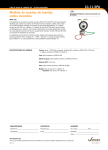
Magnetic Stripe Card Reader Option
The optional Magnetic Stripe Card Reader (MSCR) interface adds the necessary circuitry to the
basic terminal to interface a MT-211 read-only magnetic stripe card (credit card, etc.) reader unit to
the TransTerm 5A/B/C to capture and decode the data on either Track 2 or optionally Track 1 and
convert the data to ASCII. The ASCII data is then processed by the terminal as is key-entered
data. The reader is connected to the terminal by a ten inch cable, and if desired, can be mounted
on either the side or front of the terminal (add-on charge may apply). See the MT-211 documentation for more information on the operation and use of the reader.
The magnetic stripe reader interface in the TT5A is controlled by settings in Setup Register No. 4
as delineated below.
The magnetic stripe interface in the TT5B or C can be used with either a Track 1 or a Track 2 reader
or with a reader which will read both tracks; and in such case, the data read from Track 1 will take
precedence over data read from Track 2.
Setup Register Bit Assignments
TT5A SR#4
Bit #
Name
Function
1
2
3
4
5
6
7
8
—EHD
EAE
EOP
—EMS
——-
Not used by M.S. Opt
Enable Header Code
Enable Auto-Enter
Enable M.S. Input
Not used by M.S. Opt.
Enable M.S. Start/Stop Codes
Not used by M.S. Opt.
Not used by M.S. Opt.
Bit#
Name
Function
1
2
3
4
5
6
7
8
EOP
EHD
EAE
————EMS
Enable Optional Input
Enable Header Code
Enable Auto-Enter
Not used by M.S.Opt.
Not used by M.S.Opt.
Not used by M.S.Opt.
Not used by M.S.Opt.
Enable M.S. Start/Stop Codes
TT5B or TT5C SR#4
MSCR interface in the TT5A is configured by the following bits in SR4. The remaining bits in SR4
have no effect.
EOP
Enable Optional Input — When the EOP bit is set (1), the optional magnetic
stripe reader interface is activated. When the EOP bit is cleared (0), the
interface is disabled.
EHD
Enable Header Code — When the EHD bit is set (1), the ASCII data which is
produced by successfully reading a magnetic card is proceeded with a Hex
7E code to identify the source of the data as being from the reader input
rather than keyboard input.
EAE
Enable Auto-Enter — When the EAE bit is set (1), at the completion of a
swipe of a magnetic card through the reader, the terminal will perform an
ENTER operation (with different results depending upon the operating mode).
EMS
Enable Mag. Stripe Start/Stop Codes — When the EMS bit is set (1), the
magnetic stripe decoding algorithm adds the ASCII Start code to the beginning of the decoded data, and adds the ASCII Stop code to the end of the
decoded data.
PIN
1
2
3
4
5
SIGNAL
+5Vdc
CLK2
GND
DATA2
CARD2
5
1
CDIN
APPENDIX E
AuxIiliary Serial Port Option
GENERAL
The optional auxiliary serial communications port provides a means for the TransTerm 5A, B, or C
to either receive or transmit serial asynchronous ASCII data. The TT5A provides a half duplex TTL
(5V=space, 0V=mark) for the the input and output signals. The TT5B and C provides full duplex
RS-232 communications with built-in hardware and/or software hand shaking.
TT5A Aux Port Operation
The aux serial port in the TT5A can operate in one of three different modes to accommodate most
applications. These three modes are described below.
Bi-directional - In this mode, the serial input pin is used to receive data from the aux device and the
output pin is used to send data to the Aux device. The port cannot send and receive simultaneously and it is up to the user to make sure that this does not occur, otherwise data will be
corrupted.
Output Only - In this mode, the Output pin is used to send serial data to the external device and the
Input pin (2) is used as a Clear-to-Send input. When the Input pin is high, output is allowed and
when the Input pin is low, output is disallowed.
Input Only - In this mode, the Input pin is used to receive serial data from the external device and
the Output pin is used as a Ready signal. The Ready signal is high (+V) when the port is ready to
receive data, and it is low when the port is not ready to receive. Ready will go low when the 250
byte input buffer is 3/4 full and will go back high when the buffer is 3/4 empty. This mechanism is
used to throttle data transmission from very fast devices. The Ready signal may be tied to the
external device’s CTS input.
Electrical Interface
The signals for the TT5A Aux port are provided on a 5-pin circular DIN connector. The pin assignments are as follows:
Pin #
Description
1
2
3
4
+5VDC output
Serial data input
Signal Ground
Serial data output
5
1
CDIN
TT5B/C Auxiliary Serial Port Operation
The TT5B/C auxiliary serial port offers more flexibility than the TT5A aux port. The
TT5B/C port is full duplex and has built-in hardware handshaking. The port can both
receive and transmit data simultaneously, and has two separate 250 byte buffers in
which to spool data flow in each direction. Software hand-shaking with X-ON/X-OFF
protocol is recognized by the aux serial transmitter and generated by the receive logic.
The protocol is enabled and disabled by the EXP bit in Setup Register 2.
Communications Format
Data bits/character
Parity Bit
Stop Bit
Baud Rate(s)
- 8
- None
- 1
- 110 to 19,200
SETUP Register Assignments
The auxiliary serial port is configured by the bits in Setup Register 4 of the TT5A or
Setup Register 6 of the TT5B and C. The operating mode and baud rate of the auxiliary
port are initialized at terminal reset, or power-up. If either value is changed via the
Setup mode, the terminal should be reset to invoke the new setup values. TT5A SR#4
is defined as follows:
TT5A SR#4
Bit #
Description
1
3
0
1
0
1
0
1
0
1
0
0
1
1
0
0
1
1
0
0
0
0
1
1
1
1
9600
4800
2400
1200
19,200
300
150
110
7
8
Operating Mode
0
1
0
1
0
0
1
1
Bi-directional
Output Only
Input Only
Not Allowed
2
Baud Rate
TT5B SR#6
Bit
Name
Function
1
2
3
4
5
6
7
8
BR1
BR2
BR3
PS1
PS2
PEN
DBS
CSE
Baud Rate Selection
Baud Rate Selection
Baud Rate Selection
Parity Selection
Parity Selection
Parity Enable
7/8 Data Bits
CTS Enable
The above Setup bits have the same definition as those in SR 1.
Software Control
Serial data input via the AUX port is transmitted to the host computer as if it had been
entered from the keyboard of the terminal.
Serial data from the host computer is either sent to the display of the terminal or sent to
the AUX port. The host computer can direct the terminal where to send data with the
following control codes:
DC2 (12H) -> Will direct data from the host computer to the TT5A/B/C AUX port.
DC4 (14H) -> Will direct data from the host computer to the TT5A/B/C display.
All characters received by the terminal after a DC2 will be sent to the AUX port until the
terminal receives a DC4.
Auxiliary Serial Port Connector (DE9F) Pin/Signal Definition (TT5B/C only)
PIN #
1
2
3
4
5
6
7
8
9
I/O
NC
I
O
O
NC
O
I
NC
DESCRIPTION
Carrier Detect
Receive Data
Transmit Data
Data Terminal Ready
Ground
Data Set Ready
Request To Send
Clear To Send
Ring
APPENDIX F
Counter Inputs
Counter inputs are available on the TT5A, B and C models. The TT5A supports three counter
inputs while the B and C models support four. The counters accumulate count values based on the
opening and closing of external dry switch contacts. Each internal counter will count to 99,999,999
decimal. A count is recorded by shorting the counter input signal to DC ground. For each valid
count input, the contact must remain closed for a minimum duration of 20 milliseconds. The maximum count rate is 20 counts per second. Escape sequence commands are used to transmit the
current count values, clear the counters and determine the switch status (open or closed). The
TT5B/C counters support additional commands to load counters with preset values.
TT5A COUNTER INPUT
This option provides three internal counters. The switches interface to the TT5A via a 5-pin DIN
connector.
Pin #
1.
2.
3.
4.
5.
Description
Not used
Counter #1 input
Signal Ground
Counter #2 input
Counter #3 input
5
1
CDIN
TT5A COMMANDS - The counters are controlled by ESCape sequences received via the serial
port. The terminal responds as follows:
Command
ESC Y 0
Response
ESC Y 1
Transmits the value stored in counter #1 in decimal. First the
value is sent (with zeros suppressed) then a carriage return (CR) and optional line feed (LF).
Transmits the value stored in counter #2 in decimal.
Transmits the value stored in counter #3 in decimal.
Clears the value stored in Count #1.
Clears the value stored in Count #2.
Clears the value stored in Count #3.
ESC Y 2
ESC Y 3
ESC Y 4
ESC Y 5
ESC Y 6
Where;
Transmits the status of the three switches, “0” for open and “1” for
closed. The counter #1 is first, Counter #2 is second and counter #3 is last
(out the RS-232 port).
Example: 001
(1 & 2 are open, 3 is closed)
ESC = ASCII character (1B Hex)
“Y” = ASCII character (59 Hex)
“0” through “6” = ASCII characters (30 to 39 Hex)
TT5B COUNTER INPUT
This option provides four internal counters. The switches interface to the TT5B via a 5-pin DIN
connector.
Pin#
Description
5
1
1.
2.
3.
4.
5.
Counter
Counter
Ground
Counter
Counter
#4
#1
#2
#3
CDIN
TT5B COMMANDS - The counters are controlled by ESCape sequences received via the serial
port. The terminal responds as follows:
Command Response
ESC I C
ESC I S
Clears the values stored in all four counters.
Transmits the status of the four switches, “0” for open “1” for closed. Counter
#1 is first, Counter #2 is second, Counter #3 is third and #4 is last. (transmitted out the serial port)
Example: 0010
(1, 2 & 4 are open, 3 is closed)
ESC I X
Transmits the decimal values stored in all four counters (separated by a space).
Example: 25 49 33403 0
(25 in #1, 49 in #2, 33403 in #3 etc)
ESC I 1 C
ESC I 2 C
ESC I 3 C
ESC I 4 C
ESC I 1 X
Clears the value stored in Count #1 (set to zero).
Clears the value stored in Count #2.
Clears the value stored in Count #3.
Clears the value stored in Count #4.
Transmits the value stored in Counter #1 in decimal. First the value is sent
(with zeros suppressed) then a carriage return (CR) and optional line feed
(LF).
Transmits the value stored in Counter #2.
Transmits the value stored in Counter #3.
Transmits the value stored in Counter #4.
Loads Counter #1 with the decimal value “ddd”.
Loads Counter #2 with the decimal value “ddd”.
Loads Counter #3 with the decimal value “ddd”.
Loads Counter #4 with the decimal value “ddd”.
ESC I 2 X
ESC I 3 X
ESC I 4 X
ESC I 1 L ddd a
ESC I 2 L ddd a
ESC I 3 L ddd a
ESC I 4 L ddd a
Where;
ESC =
“I” =
“ddd” =
“a” =
ASCII character (1B Hex)
ASCII character (49 Hex)
1 - 8 ASCII digits - The value to store in the counter.
terminating character - If less than 8 digits are to be loaded, any non-digit
character will terminate this command. For example, to load Counter #2
with 1050 send:
ESC I 2 L 1050$ (where $ is the terminator)
APPENDIX G
Relays and Relay Drivers
TT5A RELAY DRIVER OPTION
This option provides 12 VDC source to drive a relay from a TransTerm 5A data terminal. This relay
could trigger an alarm, light bulb, door opener or larger relay etc. The option provides two output
lines from the TT5A, one to connect to the positive terminal of a 12VDC relay, and the other to the
negative terminal. The driver is controlled by ESCape commands sent from the host computer.
The two output lines exit the TT5A out the back or side of the unit. A relay must be selected that
matches the voltage and current requirements of the switched device.
TT5A COMMANDS - The driver is controlled by ESCape sequences received via the serial port.
The terminal responds as follows:
Command Response
ESC P n
If n = 0, the driver stays ON continually.
IF n = 1, the driver will pulse for 100ms.
IF n = 2, the driver will pulse for 200ms.
“ “ “ “ “ “ “ “ “ “
IF n = 9, the driver will pulse for 900ms.
(“n” is a variable from 0 to 9)
ESC O
Will turn the driver OFF.
Where;
ESC =
“P” =
“O” =
“n” =
ASCII
ASCII
ASCII
ASCII
character (1B Hex)
character (50 Hex)
character (4F Hex)
character (30-39 Hex)
TT5B/C RELAY OUTPUT OPTION
This option provides either two or four internal relays. Each relay can be controlled independently.
ESCape sequences sent from the host to the TransTerm can OPEN, CLOSE or PULSE a relay in
the TransTerm device. The relay is designed to open a door, flash a light, sound a siren, or trigger
a larger relay.
The relays are accessed via a terminal block on the back of the unit. Both relays use dry reed
contacts and the maximum contact rating is 10VA (20 VDC @ 500 ma). The maximum switched
voltage is 100 VDC.
TT5B/C COMMANDS - The relays are controlled by ESCape sequences received via the serial
port. The command is as follows:
Command
ESC J n x
Where;
ESC = ASCII character (1B Hex)
J = ASCII character (4A Hex)
n = The relay number (1-4), an ASCII character (31-34 Hex)
x = The relay control (0-9), an ASCII character (30-39 Hex)
The control characters are as follows:
0 = Relay OFF
1 = Relay ON
2 = Relay PULSE
3 = Relay PULSE
4 = Relay PULSE
5 = Relay PULSE
for
for
for
for
100
250
500
750
msec
msec
msec
msec
6=
7=
8=
9=
Relay
Relay
Relay
Relay
PULSE
PULSE
PULSE
PULSE
for
for
for
for
1.0
1.5
2.0
2.5
sec
sec
sec
sec
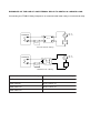
EXAMPLES OF THE USE OF AN EXTERNAL RELAY TO SWITCH A LARGER LOAD
Connecting the TT5B/C Relay Outputs to an external solid state relay or mechanical relay.
120 OR
240 VAC
TERMINAL
RELAY
12 VDC
SUPPLY
LOAD
Solid State Relay
120 OR
240 VAC
TERMINAL
LOAD
12 VDC
SUPPLY
Mechanical Relay
Potter & Brumfield Solid State Relay
Potter & Brumfield Mechanical Relay
SSR-240D25
KUP-11D15-24
SSR-240D50
KUP-14D15-12
SSR-240D110
KUP-17D15-12
SSR-480D110
APPENDIX H
Resetting Factory Default SETUP Values
In certain circumstances, due to known or unknown causes, the TT5/5A/5B
may fail to operate properly, or may become locked out of the SETUP mode
because Bit 7 of Register 3 has been set to a ‘1’. In either of these situations,
the following procedure(s) will clear the terminal’s setup memory and reprogram it with the original setting that it contained when it arrived from the
factory.
TransTerm 5 Procedure.
1. Disconnect TT5 from power.
2. Remove right side endcap and back panel.
3. Install a jumper between pins 1 and 20 of
the 40-pin LSI IC controller.
4. Apply power to TT5 and wait for power-up reset
to complete.
5. Remove power from TT5.
6. Remove jumper installed in step 3.
7. Re-assemble enclosure.
8. Restore TT5 SETUP to your requirements.
TransTerm 5A/B Procedure.
1. Disconnect TT5A/B from power.
2. Press and hold both the S1 (Red) and S2 (Blue) keys.
3. Apply power to the TT5A/B, wait for power-up
reset to complete.
4. Release S1 and S2 keys.
5. Remove power from TT5A/B.
6. Apply power to TT5A/B.
7. Restore TT5A/B SETUP to your requirements.
APPENDIX I
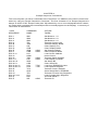
ASCII Character Set
Char
Decimal
Hex
Octal
Char
Decimal
Hex
Octal
NUL
SOH
STX
ETX
EOT
ENQ
ACK
BEL
BS
HT
LF
VT
FF
CR
SO
SI
DLE
DC1
DC2
DC3
DC4
NAK
SYN
ETB
CAN
EM
SUB
ESC
FS
GS
RS
US
SP
!
“
#
$
%
&
‘
(
)
*
+
,
.
/
0
1
2
3
4
5
6
7
8
9
:
;
<
=
>
?
00
01
02
03
04
05
06
07
08
09
10
11
12
13
14
15
16
17
18
19
20
21
22
23
24
25
26
27
28
29
30
31
32
33
34
35
36
37
38
39
40
41
42
43
44
45
46
47
48
49
50
51
52
53
54
55
56
57
58
59
60
61
62
63
00
01
02
03
04
05
06
07
08
09
0A
0B
0C
0D
0E
0F
10
11
12
13
14
15
16
17
18
19
1A
1B
1C
1D
1E
1F
20
21
22
23
24
25
26
27
28
29
2A
2B
2C
2D
2E
2F
30
31
32
33
34
35
36
37
38
39
3A
3B
3C
3D
3E
3F
000
001
002
003
004
005
006
007
010
011
012
013
014
015
016
017
020
021
022
023
024
025
026
027
030
031
032
033
034
035
036
037
040
041
042
043
044
045
046
047
050
051
052
053
054
055
056
057
060
061
062
063
064
065
066
067
070
071
072
073
074
075
076
077
@
A
B
C
D
E
F
G
H
I
J
K
L
M
N
O
P
Q
R
S
T
U
V
W
X
Y
Z
[
\
]
^
_
‘
a
b
c
d
e
f
g
h
i
j
k
l
m
n
o
p
q
r
s
t
u
v
w
x
y
z
{
|
}
~
DEL
64
65
66
67
68
69
70
71
72
73
74
75
76
77
78
79
80
81
82
83
84
85
86
87
88
89
90
91
92
93
94
95
96
97
98
99
100
101
102
103
104
105
106
107
108
109
110
111
112
113
114
115
116
117
118
119
120
121
122
123
124
125
126
127
40
41
42
43
44
45
46
47
48
49
4A
4B
4C
4D
4E
4F
50
51
52
53
54
55
56
57
58
59
5A
5B
5C
5D
5E
5F
60
61
62
63
64
65
66
67
68
69
6A
6B
6C
6D
6E
6F
70
71
72
73
74
75
76
77
78
79
7A
7B
7C
7D
7E
7F
100
101
102
103
104
105
106
107
110
111
112
113
114
115
116
117
120
121
122
123
124
125
126
127
130
131
132
133
134
135
136
137
140
141
142
143
144
145
146
147
150
151
152
153
154
155
156
157
160
161
162
163
164
165
166
167
170
171
172
173
174
175
176
177
Product Warranty
This equipment is warranted to be free from material defects and faults of
workmanship for a period of 90 days from the date of original purchase. At our option,
Computerwise agrees to repair or replace any such defective equipment.
This warranty is limited to defects arising under normal usage and does not
cover malfunctions or failures resulting from the misuse, abuse, neglect, alteration,
modification, or repairs by other than Computerwise or its authorized service agent(s).
This warranty does not cover damage to the membrane keyboard. NOTE: Repair or
replacement is the sole remedy hereunder.
This limited Warranty is in lieu of all other warranties, expressed, implied, or
statutory, including any warranties of merchantability or fitness for a particular purpose,
and extends to the original Buyer alone. In no event shall Computerwise, Inc. be liable
for lost profits or any incidental or consequential damages caused by this equipment or
related software, regardless of whether Computerwise is forewarned of such possibility
of damages.
Some states do not allow the exclusion or limitation of incidental or consequential damages, or allow limitations on how long an implied warranty lasts. If you are
a resident of such a state, the above limitations or exclusions may not apply to you. This
warranty gives you specific legal remedies, and you may also have other rights which
may vary from state to state.
To obtain warranty service during the warranty period, you must contact
Computerwise and notify us of the exact nature of the failure along with the model and
serial number of the piece of equipment (if applicable).
FCC Compliance
This equipment radiates radio frequency energy and if not installed and used
in accordance with the instructions in this manual may interfere with local RF communications. It has been tested and found to comply with the limitations for a Class B computing device pursuant to Subpart J of Part 15 of the FCC Rules for commercial environments. Operation of this equipment in a residential area is likely to cause interference in
which case the user at his own expense will be required to take whatever measures may
be necessary to correct or mask the interference by one or more of the following measures:
* Reorient the receiving antenna.
* Relocate the product with respect to the receiver.
* Move the product away from the receiver.
* Plug the product into a different AC power outlet.
If the above measures fail to solve the interference problem the user should consult the
dealer or an experienced RF technician for additional suggestions. The user may find
the
following FCC booklet helpful:
“How to Identify and Resolve Radio-TV Interference Problems”
This booklet may be ordered from the U.S. Government Printing Office.
Washington, D.C. 20402. STOCK No. 004-000-00345-4.