1
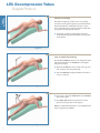
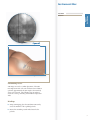
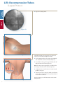
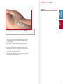
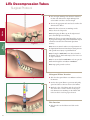
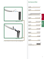
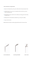
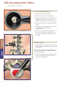
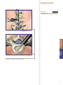
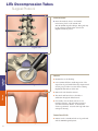
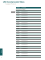
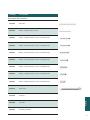
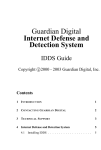
LITe Decompression Tubes
Surgical Protocol
• Minimally invasive approach
• Large selection of tubes
• Fast, rigid connection to bed
LITe
Less Invasive Technologies
LITe Decompression Tubes
Surgical Protocol
Table of Contents
Acknowledgments . . . . . . . . . . . . . . . . . . . . . . . . . . . . . . . . . . . . . . . . . . . . . . . . . . . . . . .4
Introduction . . . . . . . . . . . . . . . . . . . . . . . . . . . . . . . . . . . . . . . . . . . . . . . . . . . . . . . . . . . .4
Arm Assembly Positioning . . . . . . . . . . . . . . . . . . . . . . . . . . . . . . . . . . . . . . . . . . . . . . .6
Patient Positioning . . . . . . . . . . . . . . . . . . . . . . . . . . . . . . . . . . . . . . . . . . . . . . . . . . . . . .6
Establishing Access . . . . . . . . . . . . . . . . . . . . . . . . . . . . . . . . . . . . . . . . . . . . . . . . . . . . . .7
Markings . . . . . . . . . . . . . . . . . . . . . . . . . . . . . . . . . . . . . . . . . . . . . . . . . . . . . . . . . . . . . . .7
Dilation . . . . . . . . . . . . . . . . . . . . . . . . . . . . . . . . . . . . . . . . . . . . . . . . . . . . . . . . . . . . . . . .9
Tube Insertion . . . . . . . . . . . . . . . . . . . . . . . . . . . . . . . . . . . . . . . . . . . . . . . . . . . . . . . . .10
Subsequent Dilator Insertion . . . . . . . . . . . . . . . . . . . . . . . . . . . . . . . . . . . . . . . . . . . .10
Interbody Fusion . . . . . . . . . . . . . . . . . . . . . . . . . . . . . . . . . . . . . . . . . . . . . . . . . . . . . . .16
Disc Preparation and Removal . . . . . . . . . . . . . . . . . . . . . . . . . . . . . . . . . . . . . . . . . . .16
Closure . . . . . . . . . . . . . . . . . . . . . . . . . . . . . . . . . . . . . . . . . . . . . . . . . . . . . . . . . . . . . . .18
Contralateral Side . . . . . . . . . . . . . . . . . . . . . . . . . . . . . . . . . . . . . . . . . . . . . . . . . . . . . .18
Catalog . . . . . . . . . . . . . . . . . . . . . . . . . . . . . . . . . . . . . . . . . . . . . . . . . . . . . . . . . . . . . . .20
Warnings . . . . . . . . . . . . . . . . . . . . . . . . . . . . . . . . . . . . . . . . . . . . . . . . . . . . . . . . . . . . .22
LITe Decompression Tubes
Surgical Protocol
Acknowledgments
Stryker Spine wishes to thank the following physicians for authoring this surgical
technique:
Terrence Julien, MD
Reginald Knight, MD
Jeffrey Roh, MD
Introduction
This Surgical Technique sets forth detailed, recommended procedures for using the
LITe Decompression Tube System in order to perform a minimally invasive UniLIF
procedure. It offers guidance that you should heed but, as with any such technical
guide, each surgeon must consider the particular needs of each patient and make
appropriate adjustments when necessary and as required.
The objective of all minimally invasive surgeries (MIS) is to replicate the clinical
results of the corresponding open procedure. What sets MIS procedures apart from
open procedures is that while delivering similar clinical results, these procedures
have the potential to offer reduced intraoperative blood loss, reduced post operative
mobilization times, and minimize postoperative consumption of orally administered
narcotics.
The LITe Decompression Tube System was designed to provide a comprehensive
minimally invasive tubular platform. This would complement the existing MANTIS,
AVS PL-UniLIF, AVS PL and Reliance LITe platforms in order to perform minimally
invasive spine procedures.
4
Key Design Features
> Minimally invasive approach.
> Non-reflective PVD coating.
> Large selection of tubes.
> Fast, rigid connection to bed.
5
LITe Decompression Tubes
Patient
Positioning
Surgical Protocol
Patient Positioning
The LITe Decompression Tubes can be successfully
used under local, epidural, spinal or general anesthesia.
General anesthesia is commonly used since it is the
most comfortable for the patient and allows immediate
postoperative neurological assessment.
> The patient is prepped and draped in the usual
sterile manner for posterolateral fusion with pedicle
screw fixation.
Figure 1
Arm Assembly Positioning
The Mediflex Arm Post mounts to the hospital bed rail.
Check compatibility of the Arm Post to the hospital
bed prior to surgery.
> Mount the Arm Post to the bed rail on the opposite
side of surgeon near the patient’s hip.
> Turn the Arm Post locking mechanism clockwise to
secure it to the bed.
Figure 2
> Once secure, attach the Snake Arm to the Arm Post
and lock into place.
> The Snake Arm should be positioned across the
patient and wrap in front of the surgeon.
Note: For additional information see the Mediflex’s Flex
Arms™ Surgical User’s Manual.
Figure 3
6
48250010
Guide Pin
Patient
Positioning
Instrument Bar
Figure 4A
Figure 4B
Establishing Access
A/P images are used to confirm placement of the LITe
Decompression Tube. The tube is delivered via a dilation
system at approximately the same angle as the interbody
device to be inserted. The following steps are taken to
assure the correct positioning of the LITe Decompression
Tube.
Markings
> Using A/P imaging, place the Guide Pin transversely
across the mid-line of the cephalad pedicles.
> Draw a line extending several inches lateral to the
pedicles.
7
LITe Decompression Tubes
Patient
Positioning
Surgical Protocol
Dilation
> Repeat for caudal pedicles.
Figure 5A
Figure 5B
Carefully determine the appropriate entry point and
trajectory for the LITe Decompression Tube.
> For decompression the entry point is approximately
2cm off mid-line with a more medial trajectory.
> For a TLIF the entry point is approximately 4cm off
mid-line with a more lateral trajectory.
Note: The entry point is typically at or cephalad to the
accessory process (AP) on the transverse process.
> An incision, the size of the tube to be used, is made
parallel to the spine.
> The fascia can also be incised to make tissue dilation
easier. This is optional and can be performed later if
tissue dilation is difficult.
For this technique, we will demonstrate with a 26mm
diameter Tube.
Figure 6
8
Dilation
48080006
Dilator 1
Patient
Positioning
Instrument Bar
Figure 7
Dilation
> Place Dilator 1 through the incision. Advance the
dilator through the tissue while directing it toward
the inferior aspect of the superior lamina under
lateral imaging.
> The dilator is advanced through the lumbodorsal
fascia.
> Location of the dilator is confirmed using lateral
imaging. Use the dilator to palpate the lamina both
in the sagittal and transverse planes. This confirms
appropriate approach laterally.
> The tip of the dilator is used to sweep the paraspinal
musculature off the laminar edge.
9
LITe Decompression Tubes
Surgical Protocol
> Note the depth marking of the dilator in relation to
the skin. The dilators have depth markings laser
etched which correlate to the tube length.
> Choose the appropriate tube size based on where the
skin meets the dilator.
Dilation
Note: If the skin is between two markings on the
dilator, choose the longer tube.
Note: By keeping the dilator tip in the subperiosteal
space, this will help lessen bleeding.
Tube
Insertion
Figure 8
Note: Feel, fluoroscopy, anatomical knowledge, review
of preoperative images, and partial visualization may all
contribute towards desired instrument placement
accuracy.
Note: Great care must be taken to avoid penetration of
the ligamentum flavum and inadvertent dural puncture
with possible nerve injury or spinal fluid leak.
Note: If using the Guide Pin do not direct it lateral to
the lamina or facet, which risks injury to the nerve root
or deeper structures.
Note: To ensure that the Guide Pin is not bent, pass the
Guide Pin through the cannulation in Dilator 1.
Note: Wipe guide pin after each use.
Subsequent Dilator Insertion
Figure 9
> Slide the subsequent dilators over Dilator 1 and into
the incision.
> Use the subsequent dilators to penetrate and gently
spread and dissect soft tissue down to the lamina.
> Match the color of the dilator with the color of the
disc on the tube to ensure selection of the proper
tube diameter. Laser markings on the dilators and
tubes can also be used for proper selection.
Tube Insertion
> Slide the tube over the dilators and dock on the
lamina.
Figure 10
10
Instrument Bar
48250010
Guide Pin
48080012
Dilator 2
Figure 11A
48080014
Dilator 3
48080016
Dilator 4
Tube
Insertion
48080230
Snake Arm
Dilation
48080006
Dilator 1
48080018
Dilator 5
48080020
Dilator 6
48080022
Dilator 7
Figure 11B
> Insert the handle of the tube into the clamp of the Snake Arm.
48080026
Dilator 8
See Catalog
Decompression Tube
11
LITe Decompression Tubes
Surgical Protocol
> Secure the tube by closing the clamp.
Tube
Insertion
Figure 12
Note: To ensure proper locking, the handle of the tube
should be inserted entirely into the Snake Arm clamp.
The engagement feature of the tube is not coated with
the non-reflective PVD coating, and should not be seen
when properly inserted into the clamp.
Figure 13A
Figure 13B
12
Instrument Bar
See Catalog
Decompression Tube
48080230
Snake Arm
Tube
Insertion
Figure 14
> Secure the arm assembly by tightening the knobs.
Note: If repositioning of the tube is necessary to
expose the laminar edge, the tube can be wanded over
the pathology using the dilators. Once in the proper
location, the arm assembly is tightened.
Note: Check fitment of dilators and tubes prior to
surgery for any potential of deformation during
handling or cleaning process.
13
LITe Decompression Tubes
Surgical Protocol
Disc Preparation and Removal
Stryker Spine offers a comprehensive set of Reliance LITe decompression
instruments. This Reliance LITe set consists of:
> Penfield Elevators: Inspection of the surgical site between dura and bone.
> Nerve Hooks: Retract nerve during surgical procedure. Blunt tip to help protect
nerve.
> Nerve Retractors: Retract compressed nerve root away from disc space.
> Nerve Probes: Inspection of the surgical site. The ball tip helps to prevent
damage of nerve.
> Woodson Probes: Exploration of the disc space.
> Suction Tips: Provide suction capabilities to evacuate fluid and debris from
surgical site.
@
Kerrison Rongeurs: Remove disc material, cartilage
and hard connective tissue.
@
Bovie: Dissect soft tissue.
> Bi-Polar: Dissect soft tissue.
Penfield Bayoneted
Nerve Hook Bayoneted
Woodson Probe Bayoneted Ball Probe Bayoneted
These instruments are designed with:
> Bayoneted working shafts provide greater visibility while working through the Tube.
> Working lengths of 16cm or more for surgical procedures in the lower posterior
thoracic and lumbar spine.
> Non-reflective coating to further increase visibility by reducing glare, while working
through the Tube.
> Handle profiles and shaft diameters minimized to provide greater visibility.
> Tips rounded for safety.
Note: Instruments should be visually and physically checked for fit with each tube.
Nerve Root Retractor
Suction Tip with Bend
Micro Scissor
LITe Decompression Tubes
Surgical Protocol
Disc Preparation and Removal
> Identify the offending disc material.
> Enter the disc space at the vertebral margins.
> Resect the posterior lip of the vertebral body. This
will simultaneously help free the cartilaginous
endplate and provide direct entry to the disc space.
> Remove the offending disc material with a pituitary
rongeur.
> Intradiscal and extradiscal work can be executed, as
one would normally perform during a
microdiscectomy.
Interbody
Fusion
Disk Preparation
and Removal
Figure 15
Interbody Fusion
> A shaver (TPS Saber; Stryker Endoscopy) is ideal to
free the cartilaginous endplates while preserving the
bony endplate.
Note: Care must be taken when using a high speed
burr. Contacting the tube with a high speed drill may
reduce the life of the tube.
Figure 16A
Figure 16B
16
> The nerve root and spinal canal are explored to
ensure the decompression is complete. Once the
nerve root is decompressed, irrigate the disc space
thoroughly.
> If an interbody fusion is to be performed, complete
the discectomy, leaving the anterior and lateral
aspects of the annulus intact.
Instrument Bar
See Catalog
Decompression Tube
Figure 17B
Interbody
Fusion
Disk Preparation
and Removal
Figure 17A
> Prepare the endplate for interbody fusion.
17
LITe Decompression Tubes
Surgical Protocol
Graft Insertion
> Insert the interbody device. For detailed
instructions, please see the AVS PL and
AVS PL-UniLIF surgical technique. Bone graft may
be placed lateral, ventral and/or dorsal to the
implanted interbody device.
Figure 18A
Interbody
Fusion
Closure
> Examine the site for bleeding.
Figure 18B
> It is recommended that a visible inspection of the
surgical site be performed followed by irrigation and
suction post procedure to ensure that no existing
implantable materials are left in-situ.
Closure
> Remove the tube from the incision.
> The muscle and fascia close as the Tube is
withdrawn through the dilated tissues.
> If accessible, close the fascia with one or two
interrupted sutures. The subcutaneous tissue is
closed in an inverted manner. A subcuticular
closure is performed. Cover the skin edge with clear
waterproof dressing.
Contralateral Side
> Fixation on the contralateral side can be performed
with the MANTIS Spinal System.
Figure 19
18
Instrument Bar
Closure
Interbody
Fusion
See Catalog
Decompression Tube
19
LITe Decompression Tubes
Surgical Protocol
Catalog #
Description
Catalog
Instrument Part Numbers
20
48081603
Tube Ø16mm x 3cm
48081604
Tube Ø16mm x 4cm
48081605
Tube Ø16mm x 5cm
48081606
Tube Ø16mm x 6cm
48081607
Tube Ø16mm x 7cm
48081608
Tube Ø16mm x 8cm
48081609
Tube Ø16mm x 9cm
48082203
Tube Ø22mm x 3cm
48082204
Tube Ø22mm x 4cm
48082205
Tube Ø22mm x 5cm
48082206
Tube Ø22mm x 6cm
48082207
Tube Ø22mm x 7cm
48082208
Tube Ø22mm x 8cm
48082209
Tube Ø22mm x 9cm
48082603
Tube Ø26mm x 3cm
48082604
Tube Ø26mm x 4cm
48082605
Tube Ø26mm x 5cm
48082606
Tube Ø26mm x 6cm
48082607
Tube Ø26mm x 7cm
48082608
Tube Ø26mm x 8cm
48082609
Tube Ø26mm x 9cm
Catalog #
Description
48250010
Guide Pin
48080006
Dilator 1 (Ø6mm OD x 27.5cm)
48080012
Dilator 2 (Ø10.75mm OD x 25cm) for Ø12mm tube
48080014
Dilator 3 (Ø12.75mm OD x 23cm) for Ø14mm tube
48080016
Dilator 4 (Ø14.75mm OD x 21cm) for Ø16mm tube
48080018
Dilator 5 (Ø16.75mm OD x 19cm) for Ø18mm tube
48080020
Dilator 6 (Ø18.75mm OD x 17cm) for Ø20mm tube
48080022
Dilator 7 (Ø20.75mm OD x 15cm) for Ø22mm tube
48080026
Dilator 8 (Ø24.75mm OD x 13cm) for Ø26mm tube
48080230
Snake Arm
48250240
Arm Post
48080000
Container
48080001
Auxiliary Container
Catalog
Instrument Part Numbers
21
LITe Decompression Tubes
Surgical Protocol
Notes
EU Operations
Z.I. Marticot
33610 Cestas - FRANCE
t: +33 (0)5 57 97 06 30
f: +33 (0)5 57 97 06 31
www.stryker.com
US Operations
2 Pearl Court
Allendale, NJ 07401 - USA
t: +1 201 760 8000
f: +1 201 760 8108
www.stryker.com
A surgeon must always rely on his or her own professional clinical judgment when deciding to use which
products and/or techniques on individual patients. Stryker is not dispensing medical advice and recommends
that surgeons be trained in implant surgeries before performing any surgeries.
The information presented is intended to demonstrate the breadth of Stryker product offerings. Always refer
to the package insert, product label and/or user instructions before using any Stryker product. Products may
not be available in all markets. Product availability is subject to the regulatory or medical practices that govern
individual markets. Please contact your Stryker representative if you have questions about the availability of
Stryker products in your area.
Stryker Corporation or its divisions or other corporate affiliated entities own, use or have applied for the
following trademarks or service marks: AVS, LITe, MANTIS and Stryker. All other trademarks are trademarks
of their respective owners or holders.
Literature Number: TLDECST09091
MS/GS 08/10
Copyright © 2010 Stryker
Printed in USA