Download User`s Manual - Zesta Engineering Ltd.

Transcript
User's Manual
ZEL - 2500
Self-Tune Fuzzy / PID
Process / Temperature Controller
UM25001F
ZESTA ENGINEERING LTD.
Warning Symbol
The Symbol calls attention to an operating procedure, practice, or the like, which, if not correctly performed or
adhered to, could result in personal injury or damage to or destruction of part or all of the product and system.
Do not proceed beyond a warning symbol until the indicated conditions are fully understood and met.
Use the Manual
Installers
Basic Function User
Enhanced Function User
System Designer
Expert User
2
Read Chapter 1, 2
Read Chapter 1, 3, 5
Read Chapter 1, 3, 4, 5
Read All Chapters
Read Page 11
UM25001C
CONTENTS
Page No
Chapter 1 Overview
1-1 Features
1-2 Ordering Code
1-3 Programming Port and DIP Switch
1-4 Keys and Displays
1-5 Menu Overview
1-6 System Modes
1-7 Parameter Description
4
7
8
9
11
12
13
Chapter 2 Installation
2-1 Unpacking
2-2 Mounting
2-3 Wiring Precautions
2-4 Power Wiring
2-5 Sensor Installation Guidelines
2-6 Thermocouple Input Wiring
2-7 RTD Input Wiring
2-8 Linear DC Input Wiring
2-9 CT / Heater Current Input Wiring
2-10 Event Input wiring
2-11 Output 1 Wiring
2-12 Output 2 Wiring
2-13 Alarm 1 Wiring
2-14 Alarm 2 Wiring
2-15 RS-485
2-16 RS-232
2-17 Analog Retransmission
2-18 Programming Port
21
21
22
23
24
25
26
26
28
29
30
32
34
35
36
37
38
39
Chapter 3 Programming the Basic Function
3-1 Input 1
3-2 OUT1 & OUT2 Types
3-3 Rearrange User Menu
3-4 Display SV Instead of PV
3-5 Heat Only Control
3-6 Cool Only Control
3-7 Heat - Cool Control
3-8 Dwell Timer
3-9 Process Alarms
3-10 Deviation Alarms
3-11 Deviation Band Alarms
3-12 Heater Break Alarm
3-13 Loop Break Alarm
3-14 Sensor Break Alarm
3-15 SP1 Range
3-16 PV1 Shift
3-17 Failure Transfer
3-18 Bumpless Transfer
3-19 Self-tuning
3-20 Auto-tuning
40
41
42
42
43
44
45
47
48
50
51
52
53
54
54
55
56
57
58
59
Page No
3-21 Manual Tuning
3-22 Signal Conditioner DC Power Supply
3-23 Manual Control
3-24 Display Mode
3-25 Heater Current Monitoring
3-26 Reload Default Values
61
64
65
66
67
67
Chapter 4 Programming the Full Function
4-1 Event Input
4-2 Second Set Point
4-3 Second PID Set
4-4 Ramp & Dwell
4-5 Remote Set Point
4-6 Differential Control
4-7 Output Power Limits
4-8 Data Communication
4-9 Analog Retransmission
4-10 Digital Filter
4-11 Sleep Mode
4-12 Pump Control
4-13 Remote Lockout
68
69
70
71
73
74
75
76
77
78
79
80
81
Chapter 5 Applications
82
5-1 Pump / Pressure Control
5-2 Variable Period Full Wave SSR ( VPFW SSR ) 84
86
5-3 Heat Only Control
87
5-4 Cool Only Control
88
5-5 Heat - Cool Control
90
5-6 Ramp & Dwell
92
5-7 Remote Set Point
93
5-8 Differential Control
5-9 Dual Set Point / PID
94
5-10 RS-485
96
5-11 RS-232
98
5-12 Retransmit
99
Chapter 6 Calibration
100
Chapter 7 Error Codes & Troubleshooting
104
Chapter 8 Specifications
107
Appendix
A-1 Menu Existence Conditions
A-2 Factory Menu Description
A-3 Glossary
A-4 Index
A-5 Memo
A-6 Warranty
110
113
115
122
125
127
UM25001C
3
Chapter 1 Overview
1 1 Features
High accuracy 18-bit input A D
High accuracy 15-bit output D A
Fast input sample rate (5 times / second)
Two function complexity levels
User menu configurable
Pump control
Fuzzy + PID microprocessor-based control
Automatic programming
Differential control
Auto-tune function
Self-tune function
Sleep mode function
" Soft-start " ramp and dwell timer
Programmable inputs( thermocouple, RTD, mA, VDC )
Analog input for remote set point and CT
Event input for changing function & set point
Programmable digital filter
Hardware lockout + remote lockout protection
Loop break alarm
Heater break alarm
Sensor break alarm + Bumpless transfer
RS-485, RS-232 communication
Analog retransmission
Signal conditioner DC power supply
A wide variety of output modules available
Safety UL / CSA / IEC1010 1
EMC / CE EN61326
Front panel sealed to NEMA 4X & IP65
ZEL - 2500 Fuzzy Logic plus PID microprocessor-based controller, incorporates a
bright, easy to read 4-digit LED display, indicating process value. The Fuzzy Logic
technology enables a process to reach a predetermined set point in the shortest time,
with the minimum of overshoot during power-up or external load disturbance. The
units are housed in a 1/32 DIN case, measuring 24 mm x 48 mm with 98 mm behind
panel depth. The units feature three touch keys to select the various control and
input parameters. Using a unique function, you can put at most 5 parameters in front
of user menu by using SEL1 to SEL5 contained in the setup menu. This is
particularly useful to OEM's as it is easy to configure menu to suit the specific
application.
ZEL - 2500 is powered by 11-26 or 90 - 264 VDC / AC supply, incorporating a 2 amp.
control relay output, 5V logic alarm output and a 2 amp. alarm relay output as
standard whereby second alarm can be exceptionally configured into second output
for cooling purpose or dwell timer. Alternative output options include SSR drive,
triac, 4 - 20 mA and 0 - 10 volts. ZEL - 2500 is fully programmable for PT100,
thermocouple types J, K, T, E, B, R, S, N, L, 0 - 20mA, 4 -20mA and voltage signal
input, with no need to modify the unit. The input signals are digitized by using a 18bit A to D converter. Its fast sampling rate allows the ZEL - 2500 to control fast
processes such as pressure and flow. Self tune is incorporated. The self- tune can be
used to optimize the control parameters as soon as undesired control result is
observed. Unlike auto-tuning, Self-tune will produce less disturbance to the process
during tuning, and can be used any time.
4
UM25001D
Unique
Valuable
Digital communications RS-485, RS-232 or 4 - 20 mA retransmission are available as
an additional option. These options allow ZEL - 2500 to be integrated with
supervisory control system and software, or alternatively drive remote display, chart
recorders or data-loggers.
Three kinds of method can be used to program ZEL - 2500. 1. Use keys on front
panel to program the unit manually, 2. Use a PC and setup software to program
the unit via RS-485 or RS-232 COMM port and 3. Use P11A, a hand-held
programmer, to program the unit via programming port.
In last nearly a hundred years although PID control has been used and proved to be
an efficient controlling method by many industries, yet the PID is difficult to deal
with some sophisticated systems such as second and higher order systems, long timelag systems, during set point change and/or load disturbance circumstance etc. The
PID principle is based on a mathematic modeling which is obtained by tuning the
process. Unfortunately , many systems are too complex to describe in numerical
terms precisely. In addition, these systems may be variable from time to time. In
order to overcome the imperfection of PID control, the Fuzzy Technology is
introduced. What is the Fuzzy Control ? It works like a good driver. Under different
speeds and circumstances, he can control a car well with experiences he had before
and does not require the knowledge of kinetic theory of motion. The Fuzzy Logic is
a linguistic control which is different from the numerical PID control. It controls the
system by experiences and does not need to simulate the system precisely as been
controlled by PID.
PID + FUZZY CONTROL
MV
PROCESS
PID
PV
_
+
SV
FUZZY
Figure 1.1
Fuzzy PID System Block
Fuzzy Rule
Digital
information
Fuzzifier
Language
information
Fuzzy Inference
Defuzzifier
Engine
Digital
information
The function of Fuzzy Logic is to adjust PID parameters internally in order to make
manipulation output value MV more flexible and adaptive to various processes.
The Fuzzy Rule may work like these:
If temperature difference is large, and temperature rate is large, then
If temperature difference is large, and temperature rate is small, then
MV is large.
MV is small.
PID + Fuzzy Control has been proven to be an efficient method to improve the control
stability as shown by the comparison curves below:
UM25001C
5
PID control with properly tuned
PID + Fuzzy control
Temperature
Set point
Warm Up
Figure 1.2 Fuzzy PID
Enhances Control
Stability
Load Disturbance
Time
6
UM25001C
1 2 Ordering Code
ZEL - 2500 Power Input
1
2
3
4
4: 90 - 264 VAC, 50/60 HZ
5: 11 - 26 VAC or VDC
9: Special Order
Alarm 1
Signal Input
1: Standard Input
Input 1 - Universal Input
Thermocouple: J, K, T, E, B,
R, S, N, L
RTD: PT100 DIN, PT100 JIS
Current: 4 - 20mA, 0 - 20 mA.
Voltage: 0 - 1V, 0 - 5V, 1 - 5V,
0 - 10V
Input 2 - **
CT: 0 - 50 Amp. AC Current
Transformer ***
Voltage Input: 0 - 1V, 0 - 5V,
1 - 5V, 0 - 10V.
Event Input ( EI )
9: Special Order
Example
5
1: 5V Logic
Output
9: Special order
Output 1
6
Communications
0: None
1: RS-485
2: RS-232 **
3: Retransmit 4-20mA/0-20mA*
4: Retransmit 1 - 5V / 0 - 5V *
5: Retransmit 0 - 10V
9: Special order
0: None
Output 2 / Alarm 2
1: Relay rated 2A/240VAC
0: None
2: Pulsed voltage to
1: Form A Relay 2A/240VAC
drive SSR, 5V/30mA
2: Pulsed voltage to
3: Isolated
drive SSR, 5V / 30mA
4 - 20mA / 0 - 20mA *
3: Isolated 4 - 20mA / 0 - 20mA *
4: Isolated 1 - 5V / 0 - 5V *
5: Isolated 0 - 10V
5: Isolated 0 - 10V
6: Triac Output
6: Triac Output, 1A / 240VAC, SSR
1A / 240VAC,SSR
7: Isolated 20V / 25mA DC
C: Pulsed voltage to
Output Power Supply
drive SSR, 14V/40mA
8: Isolated 12V / 40 mA DC
9: Special order
Output Power Supply
9: Isolated 5V / 80mA DC
Output Power Supply
* Range set by front keyboard
** Alternative between RS-232 and Input 2 C: Pulsed voltage to
*** Need to order an accessory CT94-1 if
drive SSR, 14V/40mA
Heater Break detection is required.
A: Special order
ZEL - 2500 - 411111
90 - 264 operating voltage
Input: Standard Input
Output 1: Relay
Output 2: Relay
Alarm 1: 5V Logic Output
RS- 485 Communication Interface
Related Products
Accessories
CT94-1 = 0 - 50 Amp. AC Current Transformer
OM95-3 = Isolated 4 - 20 mA / 0 - 20 mA Analog Output Module
OM95-4 = Isolated 1 - 5V / 0 - 5V Analog Output Module
OM95-5 = Isolated 0 - 10V Analog Output Module
OM94-6 = Isolated 1A / 240VAC Triac Output Module ( SSR )
OM94-7 = 14V/40mA SSR Drive Module
DC94-1 = Isolated 20V / 25mA DC Output Power Supply
DC94-2 = Isolated 12V / 40mA DC Output Power Supply
DC94-3 = Isolated 5V / 80mA DC Output Power Supply
CM94-1 = Isolated RS-485 Interface Module
CM94-2 = Isolated RS-232 Interface Module
CM94-3 = Isolated 4 - 20 mA / 0 - 20 mA Retransmission Module
CM94-4 = Isolated 1 - 5V / 0 - 5V Retransmission Module
CM94-5 = Isolated 0 - 10V Retransmission Module
CC94-1 = RS-232 Interface Cable (2M)
CC91-3 = Programming Port Cable
UM25001C = ZEL - 2500 User's Manual
P11A = Hand-held Programmer for ZEL
Series Controller
SNA10A = Smart Network Adaptor for Third
Party Software, Converts 255
channels of RS-485 or RS-422 to
RS-232 Network
SNA10B = Smart Network Adaptor for ZE-Net
Software, Converts 255 channels
of RS-485 or RS-422 to RS-232
Network
SNA12A = Smart Network Adapter for
programming port to RS-232
interface
ZE-Set = Configuration Software
VPFW20 = 20 Amp. Variable Period Full
Wave SSR AC Power Module
VPFW50 = 50 Amp. Variable Period Full
Wave SSR AC Power Module
VPFW100 =100 Amp. Variable Period Full
Wave SSR AC Power Module
UM25001F
7
1 3 Programming Port and DIP Switch
Access Hole
Rear
Terminal
ON DIP
1234
Front
Panel
Figure 1.3 Access Hole
Overview
The programming port is used to connect to
P11A hand-held programmer for automatic
programming, also can be connected to ATE
system for automatic testing & calibration.
DIP Switch
:ON :OFF
1
2
3
4
TC, RTD, mV
Input 1
Select
0-1V, 0-5V, 1-5V, 0-10V
0-20 mA, 4-20 mA
All parameters are Unlocked
Lockout
Only SP1, SEL1 SEL5 * are unlocked
Only SP1 is unlocked
Table 1.1 DIP Switch
Configuration
All Parameters are locked
Factory Default Setting
The programming port is used for off-line automatic setup and testing procedures only. Don't attempt to make
any connection to these pins when the unit is used for a normal control purpose.
When the unit leaves the factory, the DIP switch is set so that TC & RTD are selected for input 1 and all parameters
are unlocked.
Lockout function is used to disable the adjustment of parameters as well as operation of calibration mode. However,
the menu can still be viewed even under lockout condition.
* SEL1- SEL5 represent those parameters which are selected by using SEL1, SEL2,...SEL5 parameters contained in
Setup menu. Parameters been selected are then allocated at the beginning of the user menu.
8
UM25001C
1 4 Keys and Displays
The unit is programmed by using three keys on the front panel. The available key functions are listed in following table.
Table 1.2 Keypad Operation
TOUCHKEYS
FUNCTION
DESCRIPTION
Up Key
Press and release quickly to increase the value of parameter.
Press and hold to accelerate increment speed.
Down Key
Press and release quickly to decrease the value of parameter.
Press and hold to accelerate decrement speed.
Scroll Key
Select the parameter in a direct sequence.
Press
for at least 3 seconds
Enter Key
Allow access to more parameters on user menu, also used to Enter manual
mode, auto-tune mode, default setting mode and to save calibration data
during calibration procedure.
Press
for at least 6 seconds
Start Record Key
Reset historical values of PVHI and PVLO and start to record the peak process
value.
Press
Reverse Scroll Key
Select the parameter in a reverse sequence during menu scrolling.
Press
Mode Key
Select the operation Mode in sequence.
Press
Reset Key
Press
for at least 3 seconds
Sleep Key
Press
Factory Key
4-digit Display
to display process value,
set point value, menu symbol,
parameter value, control output
value and error code etc.
Output 1
Indicator
Output 2
Indicator
Alarm 1
Indicator
Reset the front panel display to a normal display mode, also used to leave
the specific Mode execution to end up the auto-tune and manual control
execution, and to quit the sleep mode.
The controller enters the sleep mode if the sleep function ( SLEP ) is enabled
( select YES ).
By entering correct security code to allow execution of engineering programs.
This function is used only at the factory to manage the diagnostic reports.
The user should never attempt to operate this function.
How to display a 5-digit number ?
For a number with decimal point the
display will be shifted one digit right:
-199.99 will be displayed by -199.9
4553.6 will be displayed by 4553
For a number without decimal point
the display will be divided into two
alternating phases:
-19999 will be displayed by:
O1
O2
A1
C
ZESTA ZEL - 2500
3 Silicone Rubber Buttons
for ease of control setup
and set point adjustment.
Figure 1.4 Front Panel Description
45536 will be displayed by:
Table 1.3 Display Form of Characters
A
B
C
c
D
E
F
G
H
h
I
J
K
L
M
N
O
P
Q
R
S
T
U
V
W
X
Y
Z
?
=
-9999 will be displayed by:
: Confused Character
UM25001C
9
Power On
All segments of display and
indicators are left off for 0.5
second.
ZESTA ZEL - 2500
Figure 1.5 Display Sequence of
Initial Message
C
O1
O2
All segments of display and
indicators are lit for 2 seconds.
A1
ZESTA ZEL - 2500
C
O1
O2
A1
ZESTA ZEL - 2500
C
The left diagram shows program
no. 0 ( for ZEL - 2500 ) with version
35.
O1
O2
A1
ZESTA ZEL - 2500
Display Date Code and Serial
number for 2.5 seconds.
Each display stays for 1.25 seconds
O2
A1
C
O1
O2
A1
ZESTA ZEL - 2500
C
The left diagram shows Year 1998,
Month July ( 7 ), Date 31'st and
Serial number 192. This means that
the product is the 192 'th unit
produced on July 31'st, 1998.
Note that the month code A stands for
October, B stands for November and C
stands for December.
O1
O2
A1
ZESTA ZEL - 2500
C
Display the used hours for 2.5
seconds.
The 6-digit number of hour is indicated
by two successive displays and each
one stays for 1.25 seconds.
O1
The left diagram shows that the
unit has been used for 23456.2
hours since production.
O2
A1
ZESTA ZEL - 2500
10
Program Code
Program Version
Program No.
C
O1
ZESTA ZEL - 2500
Display program code of the
product for 2.5 seconds.
Each display stays for 1.25 seconds
C
UM25001C
Date Code
Date (31'st)
Month (December)
Year (1999)
1 5 Menu Overview
*3
or
User
Menu
SV Value
PV Value
*2
*1
Setup
Menu
Hand (Manual)
Control
Mode
for 3 seconds
H
C
Auto-tuning
Mode
Press
for 3 seconds to enter
the auto-tuning mode
Display
Mode
Default
Setting
Mode
FILE
for
3 seconds
To execute the
default setting
program
PVHI
PVLO
H
C
DV
PV1
PV2
PB
TI
TD
CJCT
PVR
PVRH
PVRL
Calibration
Mode
AD0
ADG
V1G
CJTL
CJG
REF1
SR1
MA1G
V2G
Apply these modes will break the control loop and
change some of the previous setting data. Make
sure that if the system is allowable to use these modes.
FUNC
COMM
PROT
ADDR
BAUD
DATA
PARI
STOP
AOFN
AOLO
AOHI
IN1
IN1U
DP1
IN1L
IN1H
IN2
IN2U
DP2
IN2L
IN2H
OUT1
O1TY
CYC1
O1FT
OUT2
O2TY
CYC2
O2FT
A1FN
A1MD
A1FT
A2FN
A2MD
A2FT
EIFN
PVMD
FILT
SELF
SLEP
SPMD
SP1L
SP1H
SP2F
DISF
SEL1
SEL2
SEL3
SEL4
SEL5
SEL1
SEL2
SEL3
SEL4
SEL5
*1
for 3
seconds
TIME
A1SP
A1DV
A2SP
A2DV
RAMP
OFST
REFC
SHIF
PB1
TI1
TD1
CPB
DB
SP2
PB2
TI2
TD2
O1HY
A1HY
A2HY
PL1
PL2
Display Go Home
The menu will revert to
PV/SV display after keyboard
is kept untouched for
2 minutes except Display
Mode Menu and Manual
Mode Menu. However, the
menu can revert to PV / SV
display at any time by
pressing
and
.
*1: The flow chart shows a
complete listing of all
parameters. For actual
application the number
of available parameters
depends on setup conditions, and should be
less than that shown in
the flow chart. See
Appendix A - 1 for the
exitence conditions of
each parameter.
*2: You can select at most 5 parameters put in front of the user
menu by using SEL1 to SEL5 contained at the bottom of setup
menu.
*3: Set DISF (display format) value in the setup menu to
determine whether PV or SV is displayed.
UM25001D
11
1 6 System Modes
The controller performs close loop control under its normal control mode condition.
The controller will maintain its normal control mode when you are operating user
menu, setup menu or display mode, reloading default values or applying event input
signal. Under certain conditions the normal control mode will transfer to an
Exception Mode. The exception modes include : Sleep Mode, Manual Mode, Failure
Mode, Calibration Mode and Auto-tuning Mode. All these modes perform in an
open loop control except the auto-tuning mode which performs ON-OFF plus PID
close loop control. The mode transfer is governed by the priority conditions. A lower
priority mode can not alter a higher priority mode, as shown in Figure 1.6.
? Mode
System Modes
Sleep Mode:
See Section 4-11.
Manual Mode:
See Section 3-23.
Failure Mode:
See Section 3-17.
Calibration Mode:
See Chapter 6.
Auto-tuning Mode:
See Section 3-20.
Normal Control Mode:
See Section 3-24, 3-26, 4-1.
Priority
High
Sleep Mode?
No
Yes
Manual Mode?
No
Figure 1.6
System Mode Priority
Yes
Failure Mode?
Low
No
Yes
Request
Calibration
Mode
Request
Auto-tuning
Mode
Request
Normal
Control
Mode
The calibration mode, auto-tuning mode and normal control mode are in the same priority level. The sleep mode is
in the highest priority.
12
1 7 Parameter Description
Table 1.4 Parameter Description
Contained Basic Parameter Display
Function Notation Format
in
100.0 C
(212.0 F)
Set point 1
Low:
SP1L
High:
SP1H
TIME
Dwell Time
Low:
0
High:
6553.5 minutes
A1SP
Alarm 1 Set point
A1DV
Alarm 1 Deviation Value
A2SP
Alarm 2 Set point
A2DV
Alarm 2 Deviation Value
RAMP
Ramp Rate
See Table 1.5, 1.6
-200.0 C
Low: (-360.0 F)
See Table 1.5, 1.7
-200.0 C
Low: (-360.0 F)
0
Low:
OFST
Low:
0
Low:
SHIF
Offset Value for P control
Reference Constant for
Specific Function
PV1 Shift (offset) Value
PB1
Proportional Band 1 Value
Low:
0
-200.0 C
(-360.0 F)
0
TI1
Integral Time 1 Value
Low:
0
High:
High: 60
200.0 C
High:
High: ( 360.0 F)
500.0 C
High:
High: (900.0 F)
High:
1000 sec
High:
TD1
Low:
0
High:
High:
360.0 sec
25.0
Low:
1
High:
High:
255 %
100
Low:
-36.0
High:
36.0 %
SP2
Derivative Time 1 Value
Cooling Proportional Band
Value
Heating-Cooling Dead Band
Negative Value= Overlap
Set point 2
PB2
Proportional Band 2 Value
Low:
0
TI2
Integral Time 2 Value
Low:
0
500.0 C
High: (900.0
F)
High:
1000 sec
0
37.8 C
(100.0 F)
10.0 C
(18.0 F)
TD2
Low:
0
High:
O1HY
Derivative Time 2 Value
Output 1 ON-OFF Control
Hysteresis
Low:
0.1
High:
A1HY
Hysteresis Control of Alarm 1
Low:
0.1
High:
A2HY
Hysteresis Control of Alarm 2
Low:
0.1
High:
PL1
Output 1 Power Limit
Low:
0
PL2
Output 2 Power Limit
Low:
0
0
: Basic Function Mode
1
: Full Function Mode
0
: No communication function
1
: RS-485 interface
2
: RS-232 interface
3
: 4 - 20 mA analog retransmission
output
: 0 - 20 mA analog retransmission
output
CPB
DB
FUNC
Setup
Menu
Default
Value
Range
SP1
REFC
User
Menu
Parameter
Description
COMM
Function Complexity Level
Communication Interface
Type
Low:
4
6
7
8
COMM Protocol Selection
UM25001D
200.0 C
High:
High: ( 360.0 F)
500.0 C
High: (900.0 F)
High:
100.0 %
High:
See Table 1.5, 1.8
5
PROT
C
High: ( 200.0
360.0 F)
0
0.0
100.0 C
(212.0 F)
10.0 C
(18.0 F)
100.0 C
(212.0 F)
10.0 C
(18.0 F)
0.0
25.0
2
0.0
10.0 C
(18.0 F)
100
100
25.0
High:
360.0 sec
55.6 C
( 100.0 F)
10.0 C
(18.0 F)
10.0 C
(18.0 F)
100 %
High:
100 %
100
: 0 - 1V analog retransmission
output
: 0 - 5V analog retransmission
output
: 1 - 5V analog retransmission
output
: 0 - 10V analog retransmission
output
: Modbus protocol RTU mode
0.1
0.1
0.1
100
1
1
0
13
Table 1.4 Parameter Description ( continued 2/7 )
Contained Basic Parameter Display
Function Notation Format
in
ADDR
BAUD
DATA
PARI
STOP
Setup
Menu
AOFN
AOLO
AOHI
IN1
14
Parameter
Description
Address Assignment of Digital
COMM
Baud Rate of Digital COMM
Data Bit count of Digital
COMM
Parity Bit of Digital COMM
Stop Bit Count of Digital
COMM
Analog Output Function
Analog Output Low Scale
Value
Analog Output High Scale
Value
IN1 Sensor Type Selection
UM25001C
Range
Low:
Default
Value
High: 255
1
0
: 0.3 Kbits/s baud rate
1
: 0.6 Kbits/s baud rate
2
: 1.2 Kbits/s baud rate
3
: 2.4 Kbits/s baud rate
4
: 4.8 Kbits/s baud rate
5
: 9.6 Kbits/s baud rate
6
: 14.4 Kbits/s baud rate
7
: 19.2 Kbits/s baud rate
8
: 28.8 Kbits/s baud rate
9
: 38.4 Kbits/s baud rate
0
: 7 data bits
1
: 8 data bits
0
: Even parity
1
: Odd parity
2
: No parity bit
0
: One stop bit
1
: Two stop bits
0
: Retransmit IN1 process value
1
: Retransmit IN2 process value
2
: Retransmit IN1 IN2 difference
3
: Retransmit IN2 IN1 difference
4
: Retransmit set point value
5
: Retransmit output 1 manipulation
6
: Retransmit output 2 manipulation
7
: Retransmit deviation(PV-SV)
5
1
0
0
process value
process value
0
value
value
Value
Low: -19999
High: 45536
Low: -19999
High: 45536
0
: J type thermocouple
1
: K type thermocouple
2
: T type thermocouple
3
: E type thermocouple
4
: B type thermocouple
5
: R type thermocouple
6
: S type thermocouple
0 C
(32.0 F)
100.0 C
(212.0 F)
1
(0)
Table 1.4 Parameter Description ( continued 3/7 )
Contained Basic Parameter Display
Function Notation Format
in
IN1
IN1U
DP1
Setup
Menu
Parameter
Description
IN1 Sensor Type Selection
IN1 Unit Selection
IN1 Decimal Point Selection
Range
7
: N type thermocouple
8
: L type thermocouple
9
: PT 100 ohms DIN curve
10
: PT 100 ohms JIS curve
11
: 4 - 20 mA linear current input
12
: 0 - 20 mA linear current input
13
: 0 - 1V linear Voltage input
14
: 0 - 5V linear Voltage input
15
: 1 - 5V linear Voltage input
16
: 0 - 10V linear Voltage input
17
: Special defined sensor curve
0
: Degree C unit
1
: Degree F unit
2
: Process unit
0
: No decimal point
1
: 1 decimal digit
2
: 2 decimal digits
3
: 3 decimal digits
Default
Value
1
(0)
0
(1)
1
IN1L
IN1 Low Scale Value
Low: -19999
High: 45536
0
IN1H
IN1 High Scale Value
Low: -19999
High: 45536
1000
IN2
IN2 Signal Type Selection
0
: IN2 no function
1
: Current transformer input
4
: 0 - 1V linear voltage input
5
: 0 - 5V linear voltage input
6
: 1 - 5V linear voltage input
7
: 0 - 10V linear voltage input
20
1
: Perform Event input function
IN2U
IN2 Unit Selection
Same as IN1U
2
DP2
IN2 Decimal Point Selection
Same as DP1
1
IN2L
IN2 Low Scale Value
Low: -19999
High: 45536
0
IN2H
IN2 High Scale Value
Low: -19999
High: 45536
1000
OUT1
Output 1 Function
O1TY
Output 1 Signal Type
UM25001C
0
: Reverse (heating ) control action
1
: Direct (cooling) control action
0
: Relay output
1
: Solid state relay drive output
2
: Solid state relay output
3
: 4 - 20 mA current module
0
0
15
Table 1.4 Parameter Description ( continued 4/7 )
Contained Basic Parameter Display
Function Notation Format
in
O1TY
CYC1
O1FT
OUT2
Parameter
Description
Output 1 Signal Type
Output 1 Cycle Time
Output 1 Failure Transfer
Mode
Output 2 Function
Range
4
: 0 - 20 mA current module
5
: 0 - 1V voltage module
6
: 0 - 5V voltage module
7
: 1 - 5V voltage module
8
: 0 - 10V voltage module
Low:
High: 100.0 sec
0.1
Select BPLS ( bumpless transfer ) or 0.0 ~ 100.0
% to continue output 1 control function as the unit
fails, power starts or manual mode starts.
0
: Output 2 no function
1
: PID cooling control
2
: Perform alarm 2 function
3
: DC power supply module
installed
O2TY
Output 2 Signal Type
Same as O1TY
CYC2
Output 2 Cycle Time
Low: 0.1
O2FT
Output 2 Failure Transfer
Mode
Setup
Menu
A1FN
Alarm 1 Function
Select BPLS ( bumpless transfer ) or 0.0 ~ 100.0
% to continue output 2 control function as the unit
fails, power starts or manual mode starts.
0
: No alarm function
1
: Dwell timer action
2
: Deviation high alarm
3
: Deviation low alarm
4
: Deviation band out of band alarm
5
: Deviation band in band alarm
6
: IN1 process value high alarm
7
: IN1 process value low alarm
8
: IN2 process value high alarm
9
: IN2 process value low alarm
10
14
: IN1 or IN2 process value high
alarm
: IN1 or IN2 process value low
alarm
: IN1 IN2 difference process value
high alarm
: IN1 IN2 difference process value
low alarm
: Loop break alarm
15
: Sensor break or A-D fails
12
13
A1MD
16
Alarm 1 Operation Mode
UM25001D
0
18.0
BPLS
0
0
High: 100.0 sec
11
Default
Value
0
:
Normal alarm action
1
:
Latching alarm action
2
:
Hold alarm action
3
:
Latching & Hold action
18.0
BPLS
2
0
Table 1.4 Parameter Description ( continued 5/7 )
Contained Basic Parameter Display
Function Notation Format
in
Parameter
Description
Range
0
: Alarm output OFF as unit fails
1
: Alarm output ON as unit fails
Default
Value
A1FT
Alarm 1 Failure Transfer
Mode
A2FN
Alarm 2 Function
Same as A1FN
2
A2MD
Alarm 2 Operation Mode
Same as A1MD
0
A2FT
Alarm 2 Failure Transfer
Mode
Same as A1FT
1
EIFN
Event Input Function
0
: Event input no function
1
: SP2 activated to replace SP1
2
: PB2, TI2, TD2 activated to replace
PB1, TI1, TD1
3
: SP2, PB2, TI2, TD2 activated to
replace SP1, PB1, TI1, TD1
4
: Reset alarm 1 output
5
: Reset alarm 2 output
6
: Reset alarm 1 & alarm 2
7
: Disable Output 1
8
: Disable Output 2
9
: Disable Output 1 & Output 2
10
Setup
Menu
PVMD
PV Mode Selection
FILT
Filter Damping Time
Constant of PV
1
: Lock All Parameters
0
: Use PV1 as process value
1
: Use PV2 as process value
2
: Use PV1
3
1
PV2 (difference) as
process value
: Use PV2 PV1 (difference) as
process value
0
: 0 second time constant
1
: 0.2 second time constant
2
: 0.5 second time constant
3
: 1 second time constant
4
: 2 seconds time constant
5
: 5 seconds time constant
6
: 10 seconds time constant
7
: 20 seconds time constant
8
: 30 seconds time constant
9
: 60 seconds time constant
SELF
Self Tuning Function
Selection
0
: Self tune function disabled
1
: Self tune function enabled
SLEP
Sleep mode Function
Selection
0
: Sleep mode function disabled
1
: Sleep mode function enabled
0
2
0
0
17
Table 1.4 Parameter Description ( continued 6/7 )
Contained Basic Parameter Display
Function Notation Format
in
Parameter
Description
1
: Use SP1 or SP2 (depends on EIFN)
as set point
: Use minute ramp rate as set point
2
: Use hour ramp rate as set point
3
: Use IN1 process value as set point
4
: Use IN2 process value as set point
5
: Selected for pump control
0
SPMD
Setup
Menu
Calibration
Mode
Menu
18
Set point Mode Selection
Default
Value
Range
0
SP1L
SP1 Low Scale Value
Low: -19999
High: 45536
0 LC
(32.0 LF)
SP1H
SP1 High Scale Value
Low: -19999
High: 45536
1000.0 LC
(1832.0 LF)
SP2F
Format of set point 2 Value
DISF
Display Format
SEL1
Select 1'st Parameter
0
: set point 2 (SP2) is an actual value
1
: set point 2 (SP2) is a deviation
value
0
: Display PV value
1
: Display SV value
0
: No parameter put ahead
1
: Parameter TIME put ahead
2
: Parameter A1SP put ahead
3
: Parameter A1DV put ahead
4
: Parameter A2SP put ahead
5
: Parameter A2DV put ahead
6
: Parameter RAMP put ahead
7
: Parameter OFST put ahead
8
: Parameter REFC put ahead
9
: Parameter SHIF put ahead
10
: Parameter PB1 put ahead
11
: Parameter TI1 put ahead
12
: Parameter TD1 put ahead
13
: Parameter CPB put ahead
14
: Parameter DB put ahead
15
: Parameter SP2 put ahead
16
: Parameter PB2 put ahead
17
: Parameter TI2 put ahead
18
: Parameter TD2 put ahead
0
0
SEL2
Select 2'nd Parameter
Same as SEL1
0
SEL3
Select 3'rd Parameter
Same as SEL1
0
SEL4
Select 4'th Parameter
Same as SEL1
0
SEL5
Select 5'th Parameter
Same as SEL1
0
AD0
A to D Zero Calibration
Coefficient
A to D Gain Calibration
Coefficient
Low:
-360
Low:
-199.9
High: 199.9
V1G
Voltage Input 1 Gain
Calibration Coefficient
Low:
-199.9
High: 199.9
CJTL
Cold Junction Low
Temperature Calibration
Coefficient
Low:
-5.00 BC
High: 40.00 LC
ADG
High:
360
Table 1.4 Parameter Description ( continued 7/7 )
Contained Basic Parameter Display
Function Notation Format
in
Calibration
Mode
Menu
Range
CJG
Cold Junction Gain
Calibration Coefficient
Low:
-199.9
High: 199.9
REF1
Reference Voltage 1
Calibration Coefficient for
RTD 1
Low:
-199.9
High: 199.9
Low:
-199.9
High: 199.9
Low:
-199.9
High: 199.9
SR1
MA1G
V2G
Serial Resistance 1
Calibration Coefficient for
RTD 1
mA Input 1 Gain Calibration
Coefficient
Voltage Input 2 Gain
Calibration Coefficient
Low:
-199.9
High: 199.9
Low:
-19999
High: 45536
Low:
-19999
High: 45536
MV1
Historical Maximum Value of
PV
Historical Minimum Value of
PV
Current Output 1 Value
Low:
0
High: 100.00 %
MV2
Current Output 2 Value
Low:
0
High: 100.00 %
DV
Current Deviation (PV-SV)
Value
Low:
-12600
High: 12600
PV1
IN1 Process Value
Low:
-19999
High: 45536
PV2
IN2 Process Value
Low:
-19999
PB
Current Proportional Band
Value
Low:
0
TI
Current Integral Time Value
Low:
0
High: 45536
High: 500.0 LC
(900.0 LF)
High: 4000 sec
TD
Current Derivative Time
Value
Low:
0
High: 1440 sec
Cold Junction Compensation
Temperature
Low:
-40.00 LC
High: 90.00 LC
Current Process Rate Value
Low:
-16383
High: 16383
PVRH
Maximum Process Rate Value
Low:
-16383
High: 16383
PVRL
Minimum Process Rate Value
Low:
-16383
High: 16383
PVHI
PVLO
Display
Mode
Menu
Parameter
Description
CJCT
PVR
UM25001C
Default
Value
19
Input Type J_TC
K_TC T_TC
E_TC
B_TC R_TC S_TC
-120 LC -200 LC -250 LC
Range Low (-184
LF) (-328 LF) (-418 LF)
-100 LC
0 LC
0 LC
0 LC
(-148 LF) (32 LF) (32 LF)
(32 LF)
1000 LC 1370 LC 400 LC 900 LC 1820 LC 1767.8 LC 1767.8 LC
Range High (1832
LF) (2498 LF) (752 LF) (1652 LF) (3308 LF) (3214 LF) (3214 LF)
Linear ( V, mA)
or SPEC
Input Type N_TC L_TC PT.DN PT.JS
CT
-250 LC -200 LC -210 LC -200 LC
Range Low (-418
LF) (-328 LF) (-346 LF) (-328 LF)
0 Amp
-19999
700 LC 600 LC
1300 LC 900 LC
Range High (2372
LF) (1652 LF) (1292 LF) (1112 LF)
90 Amp
45536
If A1FN =
Range of A1SP
same as range of
If A2FN =
Range of A2SP
same as range of
If PVMD =
Range of SP2
same as range of
PV2.H,PV2.L
P1.2.H, P1.2.L
D1.2.H, D1.2.L
IN2
IN1, IN2
PV2.H,PV2.L
P1.2.H, P1.2.L
D1.2.H, D1.2.L
IN1
IN2
IN1, IN2
PV1
PV2
P1 2, P2 1
IN1
IN2
IN1, IN2
PV1.H, PV1.L
IN1
PV1.H, PV1.L
Table 1.5 Input ( IN1 or IN2 ) Range
Table 1.6 Range Determination for A1SP
Table 1.7 Range Determination for A2SP
Table 1.8 Range Determination for SP2
Exception: If any of A1SP, A2SP or SP2 is configured with respect to CT input, its adjustment range is
unlimited.
20
Chapter 2 Installation
Dangerous voltages capable of causing death are sometimes present in this instrument. Before
installation or beginning any troubleshooting procedures the power to all equipment must be
switched off and isolated. Units suspected of being faulty must be disconnected and removed to
a properly equipped workshop for testing and repair. Component replacement and internal
adjustments must be made by a qualified maintenance person only.
To minimize the possibility of fire or shock hazards, do not expose this instrument to rain or
excessive moisture.
Do not use this instrument in areas under hazardous conditions such as excessive shock, vibration,
dirt, moisture, corrosive gazes or oil. The ambient temperature of the areas should not exceed the
maximum rating specified in Chapter 8.
2 1 Unpacking
Upon receipt of the shipment remove the unit from the carton and inspect the unit for shipping damage.
If any damage due to transit, report and claim with the carrier. Write down the model number, serial
number, and (S/N) and date code (D/C) are labeled on the box and housing of control.
2 2 Mounting
Make panel cutout to dimension shown in Figure 2.1.
Take both mounting clamps away and insert the controller into panel cutout. Install the mounting clamps
back. Gently tighten the screws in the clamp till the controller front panels is fitted snugly in the cutout.
MOUNTING
CLAMP
45 +0.5
_0
22.2+0.3
_0
Panel
SCREW
98.0mm
12.5mm
10.0mm
Figure 2.1
Mounting Dimensions
UM25001C
21
2 3 Wiring Precautions
Before wiring, verify the label for correct model number and options. Switch
off the power while checking.
Care must be taken to ensure that maximum voltage rating specified on the
label are not exceeded.
It is recommended that power of these units to be protected by fuses or circuit
breakers rated at the minimum value possible.
All units should be installed inside a suitably grounded metal enclosure to
prevent live parts being accessible from human hands and metal tools.
All wiring must conform to appropriate standards of good practice and local
codes and regulations. Wiring must be suitable for voltage, current, and
temperature rating of the system.
The " stripped " leads as specified in Figure 2.2 below are used for power and
sensor connections.
Beware not to over-tighten the terminal screws.
Unused control terminals should not be used as jumper points as they may
be internally connected, causing damage to the unit.
Verify that the ratings of the output devices and the inputs as specified in
Chapter 8 are not exceeded.
Electric power in industrial environments contains a certain amount of noise in
the form of transient voltage and spikes. This electrical noise can enter and
adversely affect the operation of microprocessor-based controls. For this
reason we strongly recommend the use of shielded thermocouple extension
wire which connects the sensor to the controller. This wire is a twisted-pair
construction with foil wrap and drain wire. The drain wire is to be attached to
ground at one end only.
2.0mm
0.08" max.
Figure 2.2 Lead Termination
2A/240 VAC 2A/240 VAC
ALM1
+
2
1
N
L
90-264 VAC
47-63 Hz,15VA
OUT1
_
5
6
+
+
OUT2
ALM2
_
3
4
7
ALM1(LOGIC OUTPUT)
4.5 ~ 7.0 mm
0.18" ~ 0.27"
V_ ,CT_
EI_ ,TC_ V+ ,CT+ AO+ AO_
PTA
PTB EI+,COM TX1 TX2
10
11
12
13
14
8
_
_
ALM1
RTD B
B _ V
A
V_
_ CT
I
CAT. I I
TC+
PTB
9
+
+
+
+
22
UM25001C
Figure 2.3 Rear Terminal
Connection Diagram
2 4 Power Wiring
The controller is supplied to operate at 11-26 VAC / VDC or 90-264VAC.Check
that the installation voltage corresponds with the power rating indicated on the
product label before connecting power to the controller.
Fuse
90 ~264 VAC or
11 ~ 26 VAC / VDC
1
2
3
4
5
6
7
Figure 2.4
Power Supply Connections
8
9 10 11 12 13 14
This equipment is designed for installation in an enclosure which provides
adequate protection against electric shock. The enclosure must be connected
to earth ground.
Local requirements regarding electrical installation should be rigidly observed.
Consideration should be given to prevent from unauthorized person access to
the power terminals.
UM25001C
23
2 5 Sensor Installation Guidelines
Proper sensor installation can eliminate many problems in a control system. The probe should be placed so that it
can detect any temperature change with minimal thermal lag. In a process that requires fairly constant heat
output, the probe should be placed closed to the heater. In a process where the heat demand is variable, the probe
should be closed to the work area. Some experiments with probe location are often required to find this optimum
position.
In a liquid process, addition of a stirrer will help to eliminate thermal lag. Since the thermocouple is basically a
point measuring device, placing more than one thermocouple in parallel can provide an average temperature
readout and produce better results in most air heated processes.
Proper sensor type is also a very important factor to obtain precise measurements. The sensor must have the
correct temperature range to meet the process requirements. In special processes the sensor might need to have
different requirements such as leak-proof, anti-vibration, antiseptic, etc.
Standard sensor limits of error are A4degrees F ( A2degrees C ) or 0.75% of sensed temperature (half that for
special ) plus drift caused by improper protection or an over-temperature occurrence. This error is far greater than
controller error and cannot be corrected on the sensor except by proper selection and replacement.
24
UM25001C
2 6 Thermocouple Input Wiring
Thermocouple input connections are shown in Figure 2.5. The correct type of thermocouple extension lead-wire
or compensating cable must be used for the entire distance between the controller and the thermocouple,
ensuring that the correct polarity is observed throughout. Joints in the cable should be avoided, if possible.
If the length of thermocouple plus the extension wire is too long, it may affect the temperature measurement. A
400 ohms K type or a 500 ohms J type thermocouple lead resistance will produce 1 degree C temperature error
approximately.
ON
1
3
4
5
6
7
2
8
9 10 11 12 13 14
2
1
3
Figure 2.5
Thermocouple Input Wiring
4
DIP Switch
The colour codes used on the thermocouple extension leads are shown in Table 2.1.
Table 2.1 Thermocouple Cable Colour Codes
Thermocouple
Type
Cable
Material
T
Copper ( Cu )
Constantan
( Cu-Ni )
J
Iron ( Fe )
Constantan
( Cu- Ni )
British
BS
American
ASTM
German
DIN
French
NFE
+ white
blue
* blue
+ blue
red
* blue
+ red
brown
* brown
+ yellow
blue
* blue
+ yellow
blue
* black
+ white
red
* black
+ red
blue
* blue
+ yellow
black
* black
K
Nickel-Chromium
( Ni-Cr )
Nickel-Aluminum
( Ni-Al )
+ brown
blue
* red
+ yellow
red
* yellow
+ red
green
* green
+ yellow
purple
* yellow
R
S
Pt-13%Rh,Pt
Pt-10%Rh,Pt
+ white
blue
* green
+ black
red
* green
+ red
white
* white
+ yellow
green
* green
B
Pt-30%Rh
Pt-6%Rh
Use
Copper Wire
+grey
red
* grey
+red
grey
* grey
Use
Copper Wire
* Colour of overall sheath
UM25001C
25
2 7 RTD Input Wiring
RTD connection are shown in Figure 2.6, with the compensating lead connected to terminal 9. For two-wire RTD
inputs, terminals 9 and 10 should be linked. The three-wire RTD offers the capability of lead resistance
compensation provided that the three leads should be of same gauge and equal length.
Two-wire RTD should be avoided, if possible, for the purpose of accuracy. A 0.4 ohm lead resistance of a two-wire
RTD will produce 1 degree C temperature error.
ON
1
1
2
3
4
5
6
7
1
2
3
4
5
6
7
2
3
4
8
9 10 11 12 13 14
8
DIP Switch RTD
9 10 11 12 13 14
Figure 2.6
RTD Input Wiring
RTD
Three-wire RTD
Two-wire RTD
2 8 Linear DC Input Wiring
DC linear voltage and linear current connections for input 1 are shown in Figure 2.7 and
Figure 2.8 .
DC linear voltage and linear current connections for input 2 are shown in Figure 2.9 and
Figure 2.10 .
ON
1
3
4
5
6
7
2
8
9 10 11 12 13 14
2
1
3
4
DIP Switch
26
0~1V, 0~5V
1~5V, 0~10V
UM25001C
Figure 2.7
Input 1 Linear Voltage Wiring
ON
1 2 3 4
DIP Switch
3
4
5
6
7
1
2
8
9 10 11 12 13 14
0~20mA or
4~20mA
Figure 2.8
Input 1 Linear Current Wiring
+
1
2
3
4
5
6
7
Figure 2.9
Input 2 Linear Voltage Wiring
8
9 10 11 12 13 14
0~1V, 0~5V
1~5V, 0~10V
1
2
3
4
5
6
7
Figure 2.10
Input 2 Linear Current Wiring
8
0~20mA or
4~20mA
9 10 11 12 13 14
R=250 ohms
UM25001C
IN2= 0 5V or 1 5V
27
2 9 CT / Heater Current Input Wiring
Heater 1
Heater 2
Heater 3
Heater Supply
Contactor
Current Transformer
CT94 1
1
Fuse
2
DIN Rail
3
4
5
6
Mains
supply
7
1
2
8
9 10 11 12 13 14
Figure 2.11
CT Input Wiring for
Single Phase Heater
CT Signal Input
Contactor
Three Phase
Heater Power
Fuse
Current Transformer
Ct94 1
1
3
4
5
6
7
1
2
8
9 10 11 12 13 14
2
CT Signal Input
DIN Rail
Make sure that the total current through CT94 - 1 not exceed 50A rms.
28
Mains
supply
Figure 2.12
CT Input Wiring for
Three Phase Heater
2 10 Event Input Wiring
1
2
3
4
5
6
7
1
2
3
4
5
6
7
Figure 2.13
Event Input Wiring
8
9 10 11 12 13 14
8
9 10 11 12 13 14
Switch Input
Open Collector Input
The event input can accept a switch signal as well as an open collector signal. The event input function
( EIFN ) is activated as the switch is closed or an open collector ( or a logic signal ) is pulled down.
Also refer to Section 4-1 for event input function.
29
2 11 Output 1 Wiring
Max. 2A
Resistive
Load
3
5
4
6
120V/240V
Mains Supply
7
1
2
8
9 10 11 12 13 14
Figure 2.14
Output 1 Wiring
Relay Output Direct Drive
120V /240V
Mains Supply
1
8
2
3
5
4
6
7
9 10 11 12 13 14
Three Phase
Delta
Heater
Load
Contactor
No Fuse
Breaker
Three
Phase
Heater
Power
Relay or Triac (SSR)
Output to Drive
Contactor
SSR
+
30mA/5V
Pulsed
Voltage
_
4
120V /240V
Mains Supply
_
+
3
Load
5
6
7
1
2
8
9 10 11 12 13 14
Internal Circuit
5V
0V
30
33
5
33
6
Pulsed Voltage to Drive SSR
0 - 20mA,
4 - 20mA
3
4
5
6
Load
7
1
2
8
9 10 11 12 13 14
Linear Current
Maximum Load 500 ohms
0 - 1V, 0 - 5V
1 - 5V, 0 - 10V
1
2
3
4
5
6
Load
7
Linear Voltage
8
9 10 11 12 13 14
Minimum Load 10 K ohms
Max. 1A / 240V
Load
120V /240V
Mains Supply
Triac
3
4
5
6
7
1
2
8
9 10 11 12 13 14
Triac (SSR) Output
Direct Drive
31
2 12 Output 2 Wiring
Max. 2A
Resistive
Load
3
5
4
6
120V/240V
Mains Supply
7
1
2
8
9 10 11 12 13 14
Relay Ouput Direct Drive
Figure 2.15
Output 2 Wiring
120V /240V
Mains Supply
1
8
3
2
5
4
6
7
9 10 11 12 13 14
Three Phase
Delta
Heater
Load
Contactor
No Fuse
Breaker
Three
Phase
Heater
Power
Relay or Triac (SSR)
Output to Drive
Contactor
SSR
+
30mA/5V
Pulsed
Voltage
Load
_
120V /240V
Mains Supply
_
+
3
4
5
6
7
1
2
8
9 10 11 12 13 14
Internal Circuit
5V
0V
32
33
3
33
4
Pulsed Voltage to Drive SSR
0 - 20mA,
4 - 20mA
1
2
3
4
5
6
Load
7
Linear Current
8
9 10 11 12 13 14
0 - 1V, 0 - 5V
1 - 5V, 0 - 10V
3
4
5
6
Maximum Load 500 ohms
Load
7
1
2
8
9 10 11 12 13 14
Linear Voltage
Minimum Load 10 K ohms
Max. 1A / 240V
Load
120V /240V
Mains Supply
Triac
1
2
3
4
5
6
7
Triac (SSR) Output
Direct Drive
8
9 10 11 12 13 14
33
2 13 Alarm 1 Wiring
5V DC
Relay
Max. 2A
Resistive
Load
3
4
5
6
120V/240V
Mains Supply
7
1
2
8
9 10 11 12 13 14
Figure 2.16
Alarm 1 Wiring
Single Phase Load
5V DC
Relay
120V /240V
Mains Supply
1
8
2
3
4
5
5V
7
34
7
9 10 11 12 13 14
Internal Circuit
1K
6
0V 14
Three Phase
Delta
Heater
Load
Contactor
No Fuse
Breaker
Three Phase Load
Three
Phase
Heater
Power
2 14 Alarm 2 Wiring
Max. 2A
Resistive
Load
1
2
3
4
5
6
120V/240V
Mains Supply
7
Relay Output Direct Drive
8
9 10 11 12 13 14
Figure 2.17
Alarm 2 Wiring
120V /240V
Mains Supply
1
8
2
3
4
5
6
7
9 10 11 12 13 14
Three Phase
Delta
Heater
Load
Contactor
No Fuse
Breaker
Three
Phase
Heater
Power
Relay Output to
Drive Contactor
35
2 15 RS - 485
Figure 2.18
RS - 485 Wiring
3
5
4
6
2
8
9 10 11 12 13 14
TX1
RS-485 to RS-232
network adaptor
7
1
TX2
SNA10A or
SNA10B
RS-485
Twisted-Pair Wire
3
4
5
6
7
1
2
8
9 10 11 12 13 14
TX1
TX2
Max. 247 units can be linked
3
4
5
6
7
1
2
8
9 10 11 12 13 14
TX1
TX2
Terminator
220 ohms / 0.5W
36
RS-232
TX1
TX2
PC
2 16 RS - 232 Wiring
3
4
5
6
2
8
9 10 11 12 13 14
COM
TX1
Figure 2.18
RS - 485 Wiring
7
1
TX2
PC
Figure 2.19
RS - 232 Wiring
9-pin
RS-232 port
CC94-1
Note: If the ZEL - 2500 is configured for RS-232 communication, the input 2
and EI ( Event Input ) are disconnected internally. The unit can no longer
perform event input function (EIFN) and input 2 function.
When you insert a RS-232 module (CM94-2) to the connectors on CPU board (C250), the jumper J51 and
J52 must be modified as following: J52 must be shorted and J51 must be cut and left open. Location of
jumper is shown in the following diagram.
J52
J51
Jumper
CN54
CN55
ON DIP
1 2 3 4
SW51
U52
Figure 2.20
Location of Jumper J51/J52
1
Display
If you use a conventional 9-pin RS-232 cable instead of CC94-1, the cable must be modified according to the
following circuit diagram.
To DTE(PC) RS-232 Port
ZEL - 2500
TX1
9
TX2
10
COM
TX1
RD
TX2
TD
14 COM
GND
1
2
3
4
5
6
7
8
9
Female DB-9
1 DCD
2 RD
3 TD
4 DTR
5 GND
6 DSR
7 RTS
8 CTS
9 RI
Figure 2.21
Configuration of RS-232
Cable
37
2 17 Analog Retransmission
1
2
3
4
5
6
7
The total effective resistance of serial
loads can't exceed 500 ohms.
8
9 10 11 12 13 14
Load
Load
0 - 20mA,
4 - 20mA
Load
Indicators
PLC's
Recorders
Data loggers
Inverters etc.
Retransmit Current
3
4
5
6
7
1
2
8
9 10 11 12 13 14
The total effective resistance of parallel
loads should be greater than 10K Ohms.
Load
1 - 5 V, 0 - 5V
0 - 10V
Load
Load
Retransmit Voltage
38
Indicators
PLC's
Recorders
Data loggers
Inverters etc.
Figure 2.22 Analog
Retransmission Wiring
2 18 Programming Port
See Figure 1.3 in Section 1-3 to find the programming port location.
ON DIP
1 2 3 4
Programmer
connector and
ATE connector
inserted here
Programmer
P11A
Access hole
on the
bottom view
INPT1
Figure 2.23
Programming Port Wiring
Switch Unit
SW6400
DMM
HP 34401A
Calibrator
Fluke 5520A
NOTE:
The programming port is used for off-line automatic setup and testing procedures only. Don't attempt to
make any connection to these pins when the unit is used for a normal control purpose.
39
Chapter 3 Programming the Basic Function
This unit provides an useful parameter " FUNC " which can be used to select
the function complexity level before setup. If the Basic Mode ( FUNC = BASC )
is selected for a simple application, then the following functions are ignored and
deleted from the full function menu:
RAMP, SP2, PB2, TI2, TD2, PL1, PL2, COMM, PROT, ADDR, BAUD,
DATA, PARI, STOP, AOFN, AOLO, AOHI, IN2, IN2U, DP2, IN2L, IN2H,
EIFN, PVMD, FILT, SLEP, SPMD and SP2F.
Basic Mode Capabilities:
(1) Input 1: Thermocouple, RTD, Volt, mA
(2) Input 2: CT for heater break detection
(3) Output 1: Heating or Cooling ( Relay, SSR, SSRD, Volt, mA )
(4) Output 2 : Cooling ( Relay, SSR, SSRD, Volt, mA ), DC Power supply.
(5) Alarm 1: Relay for Deviation, Deviation Band, Process, Heater Break, Loop
Break, Sensor Break, Latch, Hold or Normal Alarm.
(6) Alarm 2: Relay for Deviation, Deviation Band, Process, Heater Break, Loop
Break, Sensor Break, Latch, Hold or Normal Alarm.
(7) Dwell Timer
(8) Heater Break Alarm
(9) Loop Break Alarm
(10) Sensor Break Alarm
(11) Failure Transfer
(12) Bumpless Transfer
(13) PV1 Shift
(14) Programmable SP1 Range
(15) Heat-Cool control
(16) Hardware Lockout
(17) Self-Tune
(18) Auto-Tune
(19) ON-OFF, P, PD, PI, PID Control
(20) User Defined Menu (SEL)
(21) Manual Control
(22) Display Mode
(23) Reload Default Values
(24) Isolated DC Power Supply
(25) PV or SV Selection
If you don’t need:
(1) Second setpoint
(2) Second PID
(3) Event input
(4) Soft start (RAMP)
(5) Remote set point
(6) Complex process value
(7) Output power limit
(8) Digital communication
(9) Analog retransmission
(10) Power shut off (Sleep Mode)
(11) Digital filter
(12) Pump control
(13) Remote lockout
then you can use Basic Mode.
3 1 Input 1
Press
to enter Setup Mode. Press
to select parameter. The upper display indicates the parameter symbol,
and the lower display indicates the selection or the value of parameter.
IN1 : Selects the sensor type and signal type for Input 1.
Range: ( Thermocouple ) J_TC, K_TC, T_TC, E_TC, B_TC, R_ TC, S_TC,
N_TC, L_TC
( RTD ) PT.DN, PT.JS
(Linear ) 4-20, 0-20, 0-1V, 0-5V, 1-5V, 0-10
Default : J_TC if LF is selected, K_TC if LC is selected.
INTU : Selects the process unit for input 1.
Range: LC, LF, PU ( process unit ) If the unit i neither LC nor LF, then selects PU.
Default: LC or LF.
DP1 : Selects the location of the decimal point for most ( not all ) process related parameters.
Range: ( For T/C and RTD ) NO.DP, 1-DP
( For Linear ) NO.DP, 1-DP, 2-DP, 3-DP
Default: 1-DP
40
IN1
IN1U
DP1
IN1L: Selects the low scale value for the Linear type input 1.
Hidden if: T/C or RTD type is selected for In1.
IN1L
IN1H: Selects the high scale value for the Linear type input 1.
Hidden if: T/C or RTD type is selected for IN1.
IN1H
How to use IN1L and IN1H :
If 4 - 20 mA is selected for IN1,let SL specifies the input signal low ( ie. 4 mA ),
SH specifies the input signal high ( ie. 20 mA ), S specifies the current input
signal value, the conversion curve of the process value is shown as follows :
process value
IN1H
Figure 3.1
Conversion Curve for Linear
Type Process Value
PV1
IN1L
SL S SH
input signal
Formula : PV1 = IN1L + ( IN1H IN1L )
S SL
SH SL
Example : A 4-20 mA current loop pressure transducer with range 0 - 15 kg/cm 2
is connected to input 1, then perform the following setup :
IN1 = 4 - 20
IN1L = 0.0
IN1U = PU
IN1H = 15.0
DP1 = 1-DP
Of course, you may select other value for DP1 to alter the resolution.
3 2 OUT1 & OUT2 Types
01TY: Selects the signal type for Output 1.
The selection should be consistent with the output 1 module installed.
The available output 1 signal types are :
RELY : Mechanical relay
SSRD : Pulsed voltage output to drive SSR
4 - 20 : 4 - 20 mA linear current output
0 - 20 : 0 - 20 mA linear current output
0 - 1V : 0 - 1V linear voltage output
0 - 5V : 0 - 5V linear voltage output
0 - 5V : 1 - 5V linear voltage output
0 - 10V : 0 - 10V linear voltage
01TY
02TY
O2TY : Selects the signal type for Output 2.
The selection should be consistent with the output 2 module installed.
The available output 2 signal types are the same as for O1TY.
The range for linear current or voltage may not be very accurate. For 0 % output,
the value for 4 - 20 mA may be 3.8 mA to 4 mA; while for 100 % output, the value
for 4 - 20 mA may be 20 mA to 21 mA. However, this deviation will not degrade
the control performance at all.
41
3 3 Rearrange User Menu
The conventional controllers are designed with a fixed parameters' scrolling. If
you need a more friendly operation to suit your application, the manufacturer
will say " sorry " to you. The ZEL - 2500 has the flexibility for you to select those
parameters which are most significant to you and put these parameters in the
front of display sequence.
SEL1 : Selects the most significant parameter for view and change.
SEL2 : Selects the 2'nd significant parameter for view and change.
SEL3 : Selects the 3'rd significant parameter for view and change.
SEL4 : Selects the 4'th significant parameter for view and change.
SEL5 : Selects the 5'th significant parameter for view and change.
Range : NONE, TIME, A1.SP, A1.DV, A2.SP, A2.DV, RAMP, OFST,
REFC, SHIF, PB1, TI1, TD1, C.PB, DB, SP2, PB2, TI2, TD2
When using the up-down key to select the parameters, you may not obtain
all of the above parameters. The number of visible parameters is dependent
on the setup condition. The hidden parameters for the specific application are
also deleted from the SEL selection.
SEL1
SEL2
SEL3
SEL4
SEL5
Example :
A1FN selects TIMR
A2FN selects DE.HI
PB1 = 10
TI1 = 0
SEL1 selects TIME
SEL2 selects A2.DV
SEL3 selects OFST
SEL4 selects PB1
SEL5 selects NONE
Now, the upper display scrolling becomes :
PV
3 4 Display SV Instead of PV
In certain applications where set point value (SV) is more important than
process value (PV) for the user, the parameter DISF ( display format ) then can
be used to achieve this purpose.
Press
keys to enter setup menu
, then press
several times
until
appears on the display. If you need the process value to be
displayed, then select
by using
or
key for DISF, If you need set
point value instead of process value to be displayed, then select
for
DISF. Also refer to the flow chart in Section 1.5 to see the location of DISF.
42
DISF
has two values:
Display process
value
Display set point
value
3 5 Heat Only Control
Heat Only ON-OFF Control : Select REVR for OUT1, Set PB1 to 0, SP1 is used
to adjust set point value, O1HY is used to adjust dead band for ON-OFF
control, TIME is used to adjust the dwell timer ( enabled by selecting TIMR for
A1FN or A2FN ). The output 1 hysteresis ( O1HY ) is enabled in case of PB1 =
0 . The heat only on-off control function is shown in the following diagram :
Setup ON - OFF:
OUT1 =
PB1 = 0
Adjust: Sp1, O1HY, TIME( if enabled)
PV
SP1+O1HY/2
SP1
Dead band = O1HY
SP1 O1HY/2
OUT1 Action
Time
ON
Figure 3.2
Heat Only
ON - OFF Control
OFF
Time
The ON-OFF control may introduce excessive process oscillation even if
hysteresis is minimized to the smallest. If ON-OFF control is set ( ie. PB1 = 0 ),
TI1, TD1, CYC1, OFST, CPB and PL1 will be hidden and have no function to the
system. The manual mode, auto-tuning, self-tuning and bumpless transfer will
be disabled too.
Heat only P ( or PD ) control : Select REVR for OUT1, set TI1 to 0, SP1 is used
to adjust set point value, TIME is used to adjust the dwell timer ( enabled by
selecting TIMR for A1FN or A2FN ). OFST been enabled in case of TI1 = 0
is used to adjust the control offset ( manual reset ). Adjust CYC1 according to
the output 1 type ( O1TY ).Generally, CYC1= 0.5 ~ 2 sec for SSRD and SSR,
CYC1=10 ~ 20 sec for relay output .CYC1 is ignored if linear output is selected
for O1TY.
O1HY is hidden if PB1 is not equal to 0. OFST Function : OFST is measured
by % with range 0 - 100.0 %. In the steady state ( ie. process has been stabilized )
if the process value is lower than the set point a definite value, say 5 C, while 20 C
is used for PB1, that is lower 25 %, then increase OFST 25 %, and vice versa. After
adjusting OFST value, the process value will be varied and eventually, coincide with
set point. Using the P control ( TI1 set to 0 ), the auto-tuning and self-tuning are
disabled. Refer to section 3-21 " manual tuning " for the adjustment of PB1 and
TD1. Manual reset ( adjust OFST ) is not practical because the load may change
from time to time and often need to adjust OFST repeatedly. The PID control
can avoid this situation.
Heat only PID control : Selecting REVR for OUT1, SP1 is used to adjust set
point value. TIME is used to adjust the dwell timer ( enabled by selecting
TIMR for A1FN or A2FN ). PB1 and TI1 should not be zero. Adjust CYC1
according to the output 1 type ( O1TY ). Generally, CYC1 = 0.5 ~ 2 sec for
SSRD and SSR, CYC1 = 10 ~ 20 sec for relay output. CYC1 is ignored if
linear output is selected for O1TY.
In most cases the self-tuning can be used to substitute the auto-tuning. See
Section 3-19. If self-tuning is not used ( select NONE for SELF ), then use
auto-tuning for the new process, or set PB1, TI1 and TD1 with historical values.
See section 3-20 for auto-tuning operation. If the control result is still
unsatisfactory, then use manual tuning to improve the control . See section
3-21 for manual tuning. ZEL - 2500 contains a very clever PID and Fuzzy
algorithm to achieve a very small overshoot and very quick response to the
process if it is properly tuned.
Setup P:
OUT1 =
TI1 = 0
CYC1 ( if RELAY, SSRD or SSR is
selected for O1TY )
Adjust:
SP1, OFST, TIME ( if enabled ),
PB1 ( = 0 ), TD1
Setup PID:
OUT1 =
O1TY
CYC1 ( if RELAY, SSRD or SSR is
selected for O1TY )
SELF = NONE or YES
Adjust:
SP1, TIME ( if enabled ), PB1 ( = 0 ),
TI1 ( = 0 ), Td1.
Auto - tuning:
Used for new process. during initial
tuning
Self - tuning:
Used for a process any time.
Manual Tuning:
May be used if self-tuning and
auto-tuning are inadequate.
43
3 6 Cool Only Control
ON-OFF control, P ( PD ) control and PID control can be used for cool control.
Set OUT1 to DIRT ( direct action ). The other functions for cool only ON - OFF
control, cool only ON - OFF control and cool only PID control are same as
descriptions in section 3-5 for heat only control except that the output variable
( and action ) for the cool control is inverse to the heat control, such as the
following diagram shows:
Setup Cool Control:
OUT1 =
PV
SP1+O1HY/2
SP1
Dead band = O1HY
SP1 O1HY/2
OUT1 Action
Time
ON
Figure 3.3
Cool Only
ON - OFF Control
OFF
Time
Refer to section 3-5 in which similar descriptions for heat only control can be applied to cool only control.
44
3 7 Heat - Cool Control
The Heat-Cool Control can use one of 6 combinations of control modes. Setup of parameters for each control
mode are shown in the following table.
Control Modes
Heat
Uses
Setup Values
Cool
Uses OUT1 OUT2 O1HY OFST PB1 TI1 TD1 CPB DB A2FN A2MD A2HY
Heat : ON-OFF
Cool : ON-OFF
OUT1
OUT2 REVR =AL2
=0
Heat : ON-OFF
Cool : P ( PD )
OUT2
OUT1 DIRT =AL2
=0
=0
DE.LO
or
NORM
PV1.L
Heat : ON-OFF
Cool : PID
OUT2
OUT1 DIRT =AL2
=0
=0
DE.LO
or
NORM
PV1.L
Heat : P ( PD )
Cool : ON-OFF
OUT1
OUT2 REVR =AL2
=0
=0
DE.HI
or
NORM
PV1.H
Heat : PID
Cool : ON-OFF
OUT1
OUT2 REVR =AL2
=0
=0
DE.HI
or
NORM
PV1.H
Heat : PID
Cool : PID
OUT1
OUT2 REVR COOL
=0
=0
: Don’t care
: Adjust to meet process
requirements
DE.HI
or
NORM
PV1.H
Table 3.1 Heat - Cool Setup
NOTE : The ON-OFF control may result excessive overshoot and undershoot problems in the process. The P
( or PD ) control will result in a deviation process value from the set point. It is recommended to use PID control
for the Heat-Cool control to produce a stable and zero offset process value.
Other Setup Required : O1TY, CYC1, O2TY, CYC2, A2SP, A2DV O1TY & O2TY are set in accordance with the
types of OUT1 & OUT2 installed. CYC1 & CYC2 are selected according to the output 1 type ( O1TY ) & output
2 type ( O2TY ).
Generally, selects 0.5~2 seconds for CYC1, if SSRD OR SSR is used for O1TY;10~20 seconds if relay is used for
O1TY, and CYC1 is ignored if linear output is used. Similar condition is applied for CYC2 selection. If OUT2 is
configured for ON-OFF control ( by selecting = Al2 ), the OUT2 acts as alarm output, and the process alarm as well
as deviation alarm ( see section 3-9 & 3-10 ) can be used. Adjust A2SP to change set point if process alarm is used,
and adjust SP1 ( with preset A2DV ) to change set point if deviation alarm is used.
Examples:
Heat PID+Cool ON-OFF : Set OUT1=REVR, OUT2==AL2, A2FN=PV1.H, A2MD=NORM, A2HY=0.1, PB1=0,
T11=0, TD1=0, and set appropriate values for O1TY and CYC1.
Heat PID+Cool PID : Set OUT1=REVR, OUT2=COOL, CPB=100, DB=-4.0, PB1=0, T11=0 TD1=0, and set
appropriate values for O1TY, CYC1, O2TY, CYC2.
If you have no idea about a new process, then use self-tunning program to optimize the PID values by selecting YES
for SELF to enable the self-tunning program. See section 3-19 for self-tunning description. You can use the autotunning program for the new process or directly set the appropriate values for PB1, T11, & TD1 according to the
historical records for the repeated systems. If the control behaviour is still inadequate, then use manual tuning to
improve the control. See section 3-21 for manual tuning.
UM25001D
45
CPB Programming : The cooling proportional band is measured by % of PB with range 1~255. Initially
set 100% for CPB and examine the cooling effect. If cooling action should be enhanced then decrease
CPB, if cooling action is too strong then increase CPB. The value of CPB is related to PB and its value
Adjustment of CPB is related to the cooling medial used. For air is used as cooling media, adjust CPB at 100(%).
For oil is used as cooling media, adjust CPB at 125(%). For water is used as cooling media, adjust CPB at 250(%).
DB Programming : Adjustment of DB is dependent on the system requirements. If more positive value
of DB ( greater dead band ) is used, an unwanted cooling action can be avoided but an excessive
overshoot over the set point will occur. If more negative value of DB ( greater overlap ) is used, an
excessive overshoot over the set point can me minimized but an unwanted cooling action will occur. It is
adjustable in the range -36.0% to 36.0% of PB1 ( or PB2 if PB2 is selected ). A negative DB value shows
an overlap area over which both outputs are active. A positive DB value shows a dead band area over
which neither output is active.
46
3 8 Dwell Timer
Alarm 1 or alarm 2 can be configured as dwell timer by selecting TIMR for A1FN or
A2FN, but not both, otherwise Er07 will appear. As the dwell timer is configured, the
parameter TIME is used for dwell time adjustment.
The dwell time is measured in minute ranging from 0 to 6553.5 minutes. Once
the process reaches the set point the dwell timer starts to count from zero until
time out.The timer relay will remain unchanged until time out. The dwell timer
operation is shown as following diagram.
Error Code
PV
SP1
Figure 3.4
Dwell Timer Function
A1 or A2
TIME
Time
ON
OFF
Timer starts
Time
If alarm 1 is configured as dwell timer, A1SP, A1DV, A1HY and A1MD are hidden. Same case is for alarm 2.
Example :
Set A1FN=TIMR or A2FN=TIMR but not both. Adjust TIME in minutes A1MD ( if A1FN=TIMR ) or
A2MD ( if A2FN=TIMR ) is ignored in this case. If alarm 1 is selected for dwell timer, an external 5V DC
relay is required to drive AC load.
47
3 9 Process Alarms
There are at most two independent alarms available by adjusting OUT2. If
=AL2 is selected for OUT2, then OUT2 will perform alarm 2 function. Now
A2FN can't be selected with NONE, otherwise Er06 will be displayed.
A process alarm sets an absolute trigger level ( or temperature ). When the
process ( could be PV1, PV 2 or PV1-PV2 ) exceeds that absolute trigger level
an alarm occurs. A process alarm is independent from set point.
Adjust A1FN ( Alarm 1 function ) in setup menu. One of 8 functions can be
selected for process alarm. These are : PV1.H, PV1.L, PV2.H, PV2.L, P1.2.H,
P1.2.L, D1.2.H, D1.2.L. When the PV1.H or PV1.L is selected the alarm
examines the PV1 value. When the PV2.H or PV2.L is selected the alarm
examines the PV2 value. When the P1.2.H or P1.2.L is selected the alarm
occurs if the PV1 or PV2 value exceed the trigger level. When the D1.2.H or
D1.2.L is selected the alarm occurs if the PV1-PV2 ( difference ) value exceeds
the trigger level. The trigger level is determined by A1SP ( Alarm 1 set point )
and A1HY ( Alarm 1 hysteresis value ) in User Menu for alarm 1. The hysteresis
value is introduced to avoid interference action of alarm in a noisy environment.
Normally A1HY can be set with a minimum ( 0.1 ) value.
A1DV and/or A2DV are hidden if alarm 1 and/or alarm 2 are set with process
alarm.
Error Code
Normal Alarm : A1MD = NORM
When a normal alarm is selected, the alarm output is de-energized in the
non-alarm condition and energized in an alarm condition.
8 Types of Process Alarms:
PV1.H, PV1.L, PV2.L, P1.2H,
P1.2L, D1.2.H, D1.2.L
Latching Alarm : A1MD = LTCH
If a latching alarm is selected, once the alarm output is energized, it will
remain unchanged even if the alarm condition is cleared. The latching alarms
are disabled when the power is shut off or if event input is applied with proper
selection of EIFN.
Process Alarm 1
Setup : A1FN, A1MD
Adjust : A1SP, A1HY
Trigger level = A1SPA1/2 A1HY
Holding Alarm : A1MD = HOLD
A holding alarm prevents an alarm from power up. The alarm is enabled
only when the process reaches the set point value ( may be SP1 or SP2,
See section 4-1 event input ). Afterwards, the alarm performs same
function as normal alarm.
Process Alarm 2
Setup : OUT2, A2FN, A2MD
Adjust : A2SP, A2HY
Trigger level = A2SPA1/2 A2HY
Latching / Holding Alarm : A1MD = LT.HO
A latching / holding alarm performs both holding and latching function.
Reset Latching alarm
1. Power off
2. Apply Event input in accordance
with proper selection of EIFN
Examples:
A1SP = 200
A1HY = 10.0
A1MD = NORM
A1FN = PV1.H
Process proceeds
205
195
48
205 ON
195
205
195
205
195 OFF
205
195
Figure 3.5
Normal Process Alarm
( 3-9 2'nd page )
A1SP = 200
A1MD = LTCH
A1HY = 10.0
A1FN = PV1.H
Process proceeds
205
195
205 ON
195
A1SP = 200
A1MD = HOLD
205
195
205
195
205
195
Figure 3.6
Latching Process Alarm
A1HY = 10.0
SP1 = 210
A1FN = PV1.L
Process proceeds
205
195
210
205
195
205
195
A1SP = 200
A1MD = LT.HO
210
205
195 ON
210
205 OFF
195
210
205
195
Figure 3.7
Holding Process Alarm
A1HY = 10.0
SP1 = 210
A1FN = PV1.L
Process proceeds
205
195
205
195
210
205
195
210
205
195 ON
210
205
195
210
205
195
Figure 3.8
Latching/Holding
Process Alarm
Although the above descriptions are based on alarm 1, the same conditions can be applied to alarm 2.
49
3 10 Deviation Alarm
OUT2 can be configured as alarm 2 by selecting=AL2. If OUT2 selects=AL2,
then output 2 will perform alarm 2 function. Now A2FN can't be selected with
NONE, otherwise Er06 will appear.
A deviation alarm alerts the user when the process deviates too far from set
point. The user can enter a positive or negative deviation value ( A1DV, A2DV )
for alarm 1 and alarm 2. A hysteresis value ( A1HY or A2HY ) can be selected to
avoid interference problem of alarm in a noisy environment. Normally, A1HY
and A2HY can be set with a minimum ( 0.1 ) value.
Trigger levels of alarm are moving with set point.
For alarm 1, Trigger levels=SP1+A1DVA1/2 A1HY.
For alarm 2, Trigger levels=SP1+A2DVA1/2 A2HY.
A1SP and/or A2SP are hidden if alarm 1 and/or alarm 2 are set with deviation
alarm. One of 4 kinds of alarm modes can be selected for alarm 1 and alarm 2.
These are: Normal alarm, Latching alarm, Holding alarm and Latching/Holding
alarm. See Section 3-9 for descriptions of these alarm modes.
Error Code
2 Types of Deviation Alarms :
DE.HI, DE.LO
Deviation Alarm 1 :
Setup : A1FN, A1MD
Adjust : SP1, A1DV, A1HY
Trigger levels=SP1+A1DVA1/2A1HY
Deviation Alarm 2 :
Setup : OUT2, A2FN, A2MD
Adjust : SP1, A2DV, A2HY
Trigger levels=SP1+A2DVA1/2A2HY
Examples:
A1FN = DE.HI, A1MD = NORM, SP1 = 100, A1DV=10, A1HY=4
Process proceeds
112 ON
108
100
112
108
100
112
108
100
112
108
100
112
108
100
OFF
Figure 3.9
Normal Deviation Alarm
A1FN = DE.HI, A1MD = LTCH, SP1 = 100, A1DV=10, A1HY=4
Process proceeds
112
108
100
112 ON
108
100
112
108
100
112
108
100
112
108
100
Figure 3.10
Latching Deviation Alarm
A1HY = DE.LO, A1MD = HOLD, SP1 = 100, A1DV= -10, A1HY=4
Process proceeds
100
92
88
100
92
88
100
92
88
100
92
88 ON
100
92
88
100
92 OFF
88
100
92
88
Figure 3.11
Holding Deviation Alarm
A1HY= DE.LO, A1MD = LT.HO, SP1 = 100, A1DV= -10, A1HY=4
Process proceeds
100
92
88
50
100
92
88
100
92
88
100
92
88 ON
100
92
88
100
92
88
100
92
88
Figure 3.12
Latching Holding
Deviation Alarm
3 11 Deviation Band Alarm
A deviation band alarm presets two reference levels relative to set point. Two
types of deviation band alarm can be configured for alarm 1 and alarm 2. These
are deviation band high alarm ( A1FN or A2FN select DB.HI ) and deviation
band low alarm ( A1FN or A2FN select DB.LO ). If alarm 2 is required, then
select =AL2 for OUT2. Now A2FN can't be selected with NONE, otherwise
Er06 will appear. A1SP and A1HY are hidden if alarm 1 is selected with
deviation band alarm. Similarly, A2SP and A2HY are hidden if alarm 2 is
selected with deviation band alarm.
Trigger levels of deviation band alarm are moving with set point. For alarm 1,
trigger levels=SP1AA1DV. For alarm 2, trigger levels=SP1AA2DV.
One of 4 kinds of alarm modes can be selected for alarm 1 and alarm 2. These
are : Normal alarm, Latching alarm, Holding alarm and Latching/Holding alarm.
See Section 3-9 for descriptions of these alarm modes.
2 Types of Deviation
Band Alarms:
DB.HI, DB.LO
Deviation Band Alarm 1:
Setup: A1FN, A1MD
Adjust: Sp1, A1DV
Trigger levels = Sp1AA1DV
Deviation Band Alarm 2:
Setup: OUT2, A2FN, A2MD
Adjust: Sp1, A2DV
Trigger levels = SP1AA2DV
Examples:
A1FN = DB.HI, A1MD = NORM, SP1 = 100, A1DV = 5
Process proceeds
ON
105
100
95 OFF
105
100
95
105 ON
100
95
105
100
95
105 OFF
100
95
Error Code
Figure 3.13
Normal Deviation
Band Alarm
A1FN = DB.LO, A1MD = LTCH, SP1 = 100, A1DV = 5
Process proceeds
105
100
95 ON
105
100
95
105
100
95
105
100
95
105
100
95
105
100
95
Figure 3.14
Latching Deviation
Band Alarm
A1FN = DB.HI, A1MD = HOLD, SP1 = 100, A1DV = 5
Process proceeds
105
100
95
105
100
95
105 ON
100
95
105 OFF
100
95
105
100
95 ON
105
100
95
Figure 3.15
Holding Deviation
Band Alarm
105
100
95
105
100
95
Figure 3.16
Latching/Holding
Deviation Band Alarm
A1FN = DB.HI, A1MD = LT.HO, SP1 = 100, A1DV = 5
Process proceeds
105
100
95
105
100
95
105 ON
100
95
105
100
95
51
3 12 Heater Break Alarm
A current transformer ( parts No. CT94-1 ) should be installed to detect the
heater current if a heater break alarm is required. The CT signal is sent to
input 2, and the PV2 will indicate the heater current in 0.1 Amp. resolution.
The range of current transformer is 0 to 50.0 Amp.
For more detailed descriptions about heater current monitoring, please see
Section 3-25.
Heater Break Alarm 1
Setup : IN2 = CT
A1FN = PV2.L
A1MD = NORM
A1HY = 0.1
Adjust : A1SP
Trigger levels : A1SP A1/2 A1HY
Example:
A furnace uses two 2KW heaters connected in parallel to warm up the process.
The line voltage is 220V and the rating current for each heater is 9.09A. If we
want to detect any one heater break, set A1SP=13.0A, A1HY=0.1
A1FN=PV2.L, A1MD=NORM, then
Heater Break Alarm 2
Setup : IN2 = CT
A2FN = PV2.L
A2MD = NORM
A2HY = 0.1
Adjust : A2SP
Trigger levels : A2SP A1/2 A2HY
No heater breaks
1 heater breaks
2 heaters breaks
Alarm !
Alarm !
20
30
10
0
52
20
40
A
50
30
10
0
20
40
A
50
30
10
0
Limitations :
1. Linear output can't use heater break
alarm.
2. CYC1 should use 1 second or
longer to detect heater current reliably.
40
A
50
Figure 3.17
Heater Break Alarm
3 13 Loop Break Alarm
A1FN selects LB if alarm 1 is required to act as a loop break alarm. Similarly, if
alarm 2 is required to act as a loop break alarm, then set OUT2 with=AL2 and
A1FN with LB.
TIME, A1SP, A1DV and A1HY are hidden if alarm 1 is configured as a loop break
alarm. Similarly, TIME, A2SP, A2DV and A2HY are hidden if alarm 2 is configured
as a loop break alarm.
One of 4 kinds of alarm modes can be selected for alarm 1 and alarm 2. These
are : Normal alarm, Latching alarm, Holding alarm and Latching/Holding alarm.
However, the Holding mode and Latching/Holding mode are not recommended
to be chosen for loop break alarm since loop break alarm will not perform
holding function even if it is set with holding or latching/holding mode. See
Section 3-9 for the descriptions of these alarm modes.
Loop Break Alarm 1
Setup: A1FN = LB
A1MD = Norm, LTCH
Loop Break Alarm 2
Setup: OUT2 = = AL2
A2FN = LB
A2MD = Norm, LTCH
Loop Break Conditions are detected during a time interval of 2TI1 ( double of
integral time, but 120 seconds maximum ). Hence the loop break alarm
doesn't respond quickly as it occurs. If the process value doesn't increase ( or
decrease ) while the control variable MV1 has reached to its maximum ( or
minimum ) value within the detecting time interval, a loop break alarm ( if
configured ) will be actuated.
Heater
Sensor
Process
Switching
Device
Figure 3.18
Loop Break Sources
Controller
Loop Break Sources: Sensor, Controller, Heater, Switching Devices
Loop Break Alarm ( if configured ) occurs when any following condition
happens:
1. Input sensor is disconnected ( or broken ).
2. Input sensor is shorted.
3. Input sensor is defective.
4. Input sensor is installed outside ( isolated from ) the process.
5. Controller fails ( A-D converter damaged ).
6. Heater ( or generally, chiller, valve, pump, motor etc. ) breaks or fails or
uninstalled.
7. Switching device ( used to drive heater ) is open or shorted.
53
3 14 Sensor Break Alarm
Alarm 1 or alarm 2 can be configured as sensor break alarm by selecting SENB
for A1FN or A2FN. If alarm 2 is required for sensor break alarm, then
OUT2 should be selected with =AL2.
The sensor break alarm is activated as soon as failure mode occurs. Refer to
Section 3-17 for failure mode conditions. Note that A-D failure also creates a
sensor break alarm. TIME,A1SP, A1DV, and A1HY are hidden if alarm 1 is
configured as a sensor break alarm. Similarly, TIME, A2SP, A2DV and A2HY are
hidden if alarm 2 is configured as a sensor break alarm.
One of 4 kinds of alarm modes can be selected for sensor break alarm. These
are: Normal alarm, Latching alarm, Holding alarm and Latching/Holding alarm.
However, the Holding alarm and Latching/Holding alarm are not recommended
to be chosen for sensor break alarm since sensor break alarm will not perform
holding function even if it is set with holding or latching/holding mode. See
Section 3-9 for the descriptions of these alarm modes.
Sensor Break Alarm 1
Setup: A1FN=SENB
A1MD=NORM, LTCH
Hidden: TIME, A1SP, A1DV
A1HY
Sensor Break Alarm 2
Setup: OUT2= =AL2
A2FN=SENB
A2MD=NORM, LTCH
Hidden: TIME , A2SP, A2DV
A2HY
3 15 SP1 Range
SP1L ( SP1 low limit value ) and SP1H ( SP1 high limit value ) in setup menu
are used to confine the adjustment range of SP1.
Setup: SP1L, SP1H
Example : A freezer is working in its normal temperature range -10 C to -15 C.
In order to avoid an abnormal set point, SP1L and SP1H are set with the
following values:
SP1L = -15 C
SP1H = -10 C
Now SP1 can only be adjusted within the range from -10 C to -15 C.
IN1H ( or sensor range high )
Sp1
SP1H
SP1L
IN1L ( or sensor range low )
54
Figure 3.19 SP1 Range
3 16 PV1 Shift
In certain applications it is desirable to shift the controller display value from its actual value. This can be easily
Accomplished by using the PV1 shift function.
Press the " scroll " key to the parameter SHIF. The value you adjust here, either positive or negative, will be added
To the actual value. The SHIF function will alter PV1.
Here is an example. A process is equipped with a heater, a sensor and a subject to be warmed up. Due to the
design and position of the components in the system, the sensor could not be placed any closer to the part.
Thermal gradient ( different temperature ) is common and necessary to an extent in any thermal system for heat to
be transferred from one point to another. If the difference between the sensor and the subject is 35 C, and the
desired temperature at the subject to be heated is 200 C, the controlling value or the temperature at the sensor
should be 235 C. You should input -35 C as to subtract 35 C from the actual process display. This in turn will
Cause the controller to energize the load and bring the process display up to the set point value.
Setup: SP1L, SP1H
Subject
Heater
Heat
Transfer
165 C
200 C
Sensor
C
35 C temperature
difference is observed
SHIF= 0
Subject
Heater
Heat
Transfer
165 C
200 C
Sensor
C
Adjust SHIF
SHIF= -35 C
Supply more heat
Subject
Heater
Heat
Transfer
200 C
235 C
Sensor
C
Display is stable
SHIF= -35 C
PV=SV
Figure 3.20
PV1 Shift Application
55
3 17 Failure Transfer
The controller will enter failure mode as one of the following conditions occurs:
1. SB1E occurs ( due to the input 1 sensor break or input 1 current below 1mA
if 4-20 mA is selected or input 1 voltage below 0.25V if 1-5 V is selected ) if
PV1, P1-2 or P2-1 is selected for PVMD or PV1 is selected for SPMD.
2. SB2E occurs ( due to the input 2 sensor break or input 2 current below 1mA
if 4-20 mA is selected or input 2 voltage below 0.25V if 1-5 V is selected ) if
PV2, P1-2 or P2-1 is selected for PVMD or PV2 is selected for SPMD.
3. ADER occurs due to the A-D converter of the controller fails.
The output 1 and output 2 will perform the failure mode function as one of the
following conditions occurs:
1. During power starts ( within 2.5 seconds ).
2. The controller enters the failure mode.
3. The controller enters the manual mode.
4. The controller enters the calibration mode.
Output 1 Failure Transfer, if activated, will perform :
1. If output 1 is configured as proportional control ( PB1 = 0 ), and BPLS is
selected for O1FT, then output 1 will perform bumpless transfer. Thereafter
the previous averaging value of MV1 will be used for controlling output 1.
2. If output 1 is configured as proportional control ( PB1 = 0 ), and a value of
0 to 100.0 % is set for O1FT, then output 1 will perform failure transfer.
Thereafter the value of O1FT will be used for controlling output 1.
3. If output 1 is configured as ON-OFF control ( PB1 = 0 ), then output 1 will be
driven OFF if O1FN selects REVR and be driven ON if O1FN selects DIRT.
Output 2 Failure Transfer, if activated, will perform :
1. If OUT2 selects COOL, and BPLS is selected for O1FT, then output 2 will
perform bumpless transfer. Thereafter the previous averaging value of MV2
will be used for controlling output 2.
2. If OUT2 selects COOL, and a value of 0 to 100.0 % is set for O2FT, then
output 2 will perform failure transfer. Thereafter the value of O1FT will be
used for controlling output 2.
Alarm 1 Failure Transfer is activated as the controller enters failure mode.
Thereafter the alarm 1 will transfer to the ON or OFF state preset by A1FT.
Exception: If Loop Break (LB) alarm or sensor Break (SENB) alarm is
configured for A1FN, the alarm 1 will be switched to ON state independent
of the setting of A1FT. If Dwell Timer (TIMR) is configured for A1FN, the alarm 1
will not perform failure transfer.
Alarm 2 Failure Transfer is activated as the controller enters failure mode.
Thereafter the alarm 2 will transfer to the ON or OFF state preset by A2FT.
Exception: If Loop Break (LB) alarm or sensor Break (SENB) alarm is
configured for A2FN, the alarm 2 will be switched to ON state independent
of the setting of A2FT. If Dwell Timer (TIMR) is configured for A2FN, the alarm 2
will not perform failure transfer.
56
Failure Mode Occurs as :
1. SB1E
2. SB2E
3. ADER
Failure Transfer of outout 1 and output 2
occurs as :
1. Power start ( within 2.5 seconds )
2. Failure mode is activated
3. Manual mode is activated
4. Calibration mode is activated
Failure Transfer of alarm 1 and alarm 2
occurs as :
1. Failure mode is activated
Failure Transfer Setup :
1. O1FT
2. O2FT
3. A1FT
4. A2FT
3 18 Bumpless Transfer
The bumpless transfer function is available for output 1 and output 2 ( provided
that OUT2 is configured as COOL ).
Bumpless Transfer is enabled by selecting BPLS for O1FT and/or O2FT and
activated as one of the following cases occurs :
1. Power starts ( within 2.5 seconds ).
2. The controller enters the failure mode. See section 3-17 for failure mode
descriptions.
3. The controller enters the manual mode. See section 3-23 for manual mode
descriptions.
4. The controller enters the calibration mode. See chapter 6 for calibration
mode descriptions.
As the bumpless transfer is activated, the controller will transfer to open-loop
control and uses the previous averaging value of MV1 and MV2 to continue
control.
Bumpless Transfer Setup:
1. O1FT = BPLS
2. O2FT = BPLS
Bumpless Transfer Occurs as:
1. Power Starts ( within 2.5 seconds )
2. Failure mode is activated
3. Manual mode is activated
4. Calibration mode is activated
Without Bumpless Transfer
PV
Figure 3.21 Benefits of Bumpless Transfer
Power interrupted
Sensor break
Set point
Large
deviation
Time
Since the hardware and software need time to be initialized, the control is
abnormal as the power is recovered and results in a large disturbance to
the process. During the sensor breaks, the process loses power.
With Bumpless Transfer
PV
Power interrupted
Sensor break
Set point
Small
deviation
Load varies
Time
After bumpless transfer configured, the correct control variable is applied
immediately as the power is recovered, the disturbance is small. During the
sensor breaks, the controller continues to control by using its previous value. If
the load doesn't change, the process will remain stable. Thereafter, once the
load changes, the process may run away. Therefore, you should not rely on a
bumpless transfer for a longer time. For fail safe reason, an additional alarm
should be used to announce the operator when the system fails. For example,
a Sensor Break Alarm, if configured, will switch to failure state and announces
the operator to use manual control or take a proper security action when the
system enters failure mode.
Warning: After system fails,
news depend on bumpless
transfer for a long time,
otherwise it might cause a
problem to the system to run
away.
57
3 19 Self
tunning
The Self-tuning which is designed by using an innovative algorithm provides
an alternative option for tuning the controller. It is activated as soon as SELF
is selected with YES. When Self-tuning is working, the controller will change
its working PID values and compares the process behavior with previous cycle.
If the new PID values achieve a better control, then changing the next PID
values in the same direction, otherwise, changing the next PID values in
reverse direction. When an optimal condition is obtained, the optimal PID
values will be stored in PB1, TI1, TD1 or PB2, TI2, TD2 which is determined
by Event Input conditions. See Section 4-1. When Self-tuning is completed,
the value of SELF will be changed from YES to NONE to disable self-tuning
function.
When the Self-tuning is enabled, the control variables are tuned slowly so that
the disturbance to the process is less than auto-tuning. Usually, the Self-tuning
will perform successfully with no need to apply additional auto-tuning.
Self-tune Menu
Selects
Disable Self-tuning
Enable Self-tuning
Default
SELF=NONE
Exceptions: The Self-tuning will be disabled as soon as one of the following
conditions occurs:
1. SELF is selected with NONE.
2. The controller is used for on-off control, that is PB=0.
3. The controller is used for manual reset, that is TI=0.
4. The controller is under loop break condition.
5. The controller is under failure mode (e.g. sensor break).
6. The controller is under manual control mode.
7. The controller is under sleep mode.
8. The controller is being calibrated.
If the self-tuning is enabled, the auto-tuning can still be used any time. The
self-tuning will use the auto-tuning results for its initial values.
Benefits of Self-tuning:
1. Unlike auto-tuning, Self-tuning will produce less disturbance to the process.
2. Unlike auto-tuning, Self-tuning doesn't change control mode during tuning
period. It always performs PID control.
3. Changing set point during Self-tuning is allowable. Hence, Self-tuning can
be used for ramping set point control as well as remote set point control
where the set point is changed from time to time.
Operation:
The parameter SELF is contained in setup menu. Refer to Section 1-5 to
obtain SELF for initiating a self-tuning.
58
Benefits of Self-tune:
1. Less disturbance to the process.
2. Perform PID control during tuning
period.
3. Available for ramping set point
control and remote set point
control.
3 20 Auto
tuning
The auto-tuning process is performed at set point.
The process will oscillate around the set point during tuning process.
Set a set point to a lower value if overshooting beyond the normal
process value is likely to cause damage.
The auto-tuning is applied in cases of :
Initial setup for a new process
The set point is changed substantially from the previous auto-tuning
value
The control result is unsatisfactory
Operation:
1. The system has been installed normally.
2. Use the default values for PID before tuning.
The default values are : PB1=PB2=18.0 F
TI1=TI2=100 sec, TD1=TD2=25.0 sec, Of course, you can use other
reasonable values for PID before tuning according to your previous
experiences. But don't use a zero value for PB1 and TI1 or PB2 and
TI2, otherwise, the auto-tuning program will be disabled.
3. Set the set point to a normal operating value or a lower value if
overshooting beyond the normal process value is likely to cause
damage.
4. Press
until
Applicable Conditions:
PB1=0, TI1=0 if PB1,TI1,TD1
assigned
PB2=0, TI2=0, if PB2, TI2, TD2
assigned
appears on the display.
5. Press
for at least 3 seconds. The upper display will begin to flash
and the auto-tuning procedure is beginning.
NOTE:
Any of the ramping function, remote set point or pump function, if used,
will be disabled once auto-tuning is proceeding.
Operation:
The auto-tuning can be applied either as the process is warming up
( Cold Start ) or as the process has been in steady state ( Warm Start ).
See Figure 3.22.
If the auto-tuning begins apart from the set point ( Cold Start ), the
unit enters Warm-up cycle. As the process reaches the set point value,
the unit enters waiting cycle. The waiting cycle elapses a double integral
time ( TI1 or TI2, dependent on the selection, see Section 4.1 ) then it
enters a learning cycle. The double integral time is introduced to allow
the process to reach a stable state. Before learning cycle, the unit
performs pre-tune function with a PID control. While in learning cycle
the unit performs post-tune function with an ON-OFF control.
Learning cycle is used to test the characteristics of the process. The data
are measured and used to determine the optimal PID values. At the
end of the two successive ON-OFF cycles the PID values are obtained
and automatically stored in the nonvolatile memory.
After the auto-tuning procedures are completed, the process display will
cease to flash and the unit revert to PID control by using its new PID
values.
During pre-tune stage the PID values will be modified if any unstable
phenomenon which is caused by incorrect PID values is detected.
Without pre-tune stage, like other conventional controller, the tuning
result will be strongly related to the time when the auto-tuning is
applied. Hence different values will be obtained every time as autotuning is completed without pre-tune. It is particularly true when the
auto-tuning are applied by using cold start and warm start.
Pre-tune Function Advantage:
Consistent tuning results can be
obtained
59
Auto-tuning
Begins
PV
Warm-up
Cycle
Auto-tuning
Complete
Waiting
Cycle
=2 Integral
Time
Learning Cycle
New PID Cycle
Set Point
Pre-tune Stage
PID Control
Figure 3.22
Auto-tuning Procedures
Post-tune Stage
ON-OFF Control
PID Control
Time
Cold Start
Auto-tuning
Begins
Pre-tune Stage
PV
Waiting
Cycle
=2 Integral
Time
Auto-tuning
Complete
Learning Cycle
New PID Cycle
Set Point
Pre-tune
Stage
PID Control
Post-tune Stage
ON-OFF Control
Warm Start
PID Control
Time
If the auto-tuning begins near the set point ( warm start ), the unit passes the warm-up cycle and enters the waiting
cycle. Afterward the procedures are same as that described for cold start.
Auto-Tuning Error
If auto-tuning fails an ATER message will appear on the upper display in cases of :
If PB exceeds 9000 ( 9000 PU, 900.0 LF or 500.0 LC ).
or if TI exceeds 1000 seconds.
or if set point is changed during auto-tuning procedure.
or if event input state is changed so that set point value is changed.
Solutions to
1. Try auto-tuning once again.
2. Don't change set point value during auto-tuning procedure.
3. Don't change event input state during auto-tuning procedure.
4. Use manual tuning instead of auto-tuning. ( See section 3-21 ).
5. Touch any key to reset
message.
60
Auto-Tuning Error
3 21 Manual Tuning
In certain applications ( very few ) using both self-tuning and auto-tuning to
tune a process may be inadequate for the control requirement, then you can
try manual tuning. Connect the controller to the process and perform the
procedures according to the flow chart shown in the following diagram.
Figure 3.23
Manual Tuning
Procedure
Use initial PID values
to control the process
Wait and Examine
the Process
No
Wait and Examine
the Process
Is
steady state
reached ?
Is
steady state
reached ?
No
Yes
Yes
Does
the process
oscillate ?
Does
the process
oscillate ?
No
No
Yes
1
2PB1
Yes
Flag
0
Pb1
0.5PB1
Flag
Pb1
PBu
Oscillating period
Pb1
Load new PID values
1.7 PBu
PB1
Tu
TI1
0.3 Tu
TD1
Wait and Examine
the Process
No
Tu
END
Is
steady state
reached ?
Yes
Does
the process
oscillate ?
NOTE :
The final PID values can't be zero.
If PBu=0 then set PB1=1.
If Tu < 1 sec, then set TI1=1 sec.
No
Yes
No
Flag=0 ?
Yes
1.6PB1
Pb1
Flag=1 ?
No
Yes
0.8PB1
Pb1
The above procedure may take a long time before reaching a new steady state
since the P band was changed. This is particularly true for a slow process. So
the above manual tuning procedures will take from minutes to hours to obtain
optimal PID values.
61
The PBu is called the Ultimate P Band and the period of oscillation Tu is
called the Ultimate Period in the flow chart of Figure 3.23 . When this
occurs, the process is called in a critical steady state. Figure 3.24 shows a
critical steady state occasion.
PV
If PB=PBu
the process sustains to oscillate
Figure 3.24
Critical Steady State
Set point
Tu
Time
If the control performance by using above tuning is still unsatisfactory, the
following rules can be applied for further adjustment of PID values :
ADJUSTMENT SEQUENCE
(1) Proportional Band ( P )
PB1 and/or PB2
(2) Integral Time ( I )
TI1 and/or TI2
(3) Derivative Time ( D )
TD1 and/or TD2
SYMPTOM
SOLUTION
Slow Response
Decrease PB1 or PB2
High overshoot or
Oscillations
Increase PB1 or PB2
Slow Response
Decrease TI1 or TI2
Instability or
Oscillations
Increase TI1 or TI2
Slow Response or
Oscillations
Decrease TD1 or TD2
High Overshoot
Increase TD1 or TD2
Table 3.2
PID Adjustment Guide
Figure 3.25 shows the effects of PID adjustment on process response.
P action
PB too low
PV
Perfect
Figure 3.25
Effects of PID Adjustment
Set point
PB too high
Time
62
I action
TI too high
PV
Figure 3.25 ( Continued )
Effects of PID Adjustment
Set point
Perfect
TI too low
Time
D action
PV
TD too low
Perfect
Set point
TD too high
Time
63
3 22 Signal Conditioner DC Power Supply
Three types of isolated DC power supply are available to supply an external transmitter
or sensor. These are 20V rated at 25mA, 12V rated at 40 mA and 5V rated at 80 mA.
The DC voltage is delivered to the output 2 terminals.
Two-line Transmitter
Set
OUT2=
(DC Power Supply)
3
4
5
6
7
1
2
8
9 10 11 12 13 14
Figure 3.26
DC Power Supply Applications
4 - 20mA
Three-line Transmitter
or sensor
Bridge Type
Sensor
OUT COM IN
3
4
5
6
3
4
5
1
2
7
1
2
8
9 10 11 12 13 14
8
9 10 11 12 13 14
V or mA
Caution:
Don't use the DC power supply beyond its rating current to avoid damage.
Purchase a correct voltage to suit your external devices. See ordering code in section 1-2.
64
6
7
3 23 Manual Control
The manual control may be used for the following purposes:
( 1 ) To test the process characteristics to obtain a step response as well as an
impulse response and use these data for tuning a controller.
( 2 ) To use manual control instead of a close loop control as the sensor fails or
the controller's A-D converter fails. NOTE that a bumpless transfer can not
be used for a longer time. See section 3-18.
( 3 ) In certain applications it is desirable to supply a process with a constant
demand.
Operation:
Press
until
( Hand Control ) appears on the display.
Press
for 3 seconds then the upper display will begin to flash and the lower
display will show
. The controller now enters the manual control mode.
Pressing
the lower display will show
and
alternately where
indicates output 1 ( or heating ) control variable value MV1 and
indicates output 2 ( or cooling ) control variable value MV2. Now you can use
up-down key to adjust the percentage values for H or C.
The controller performs open loop control as long as it stays in manual control
mode. The H value is exported to output 1 ( OUT1 ) and C value is exported to
output 2 provided that OUT2 is performing cooling function ( ie. OUT2 selects
COOL ).
Means
MV1=38.4 %
for OUT1 ( or Heating )
Means
MV2=7.63 %
for OUT2 ( or Cooling )
Exception
If OUT1 is configured as ON-OFF control ( ie. PB1=0 if PB1 is assigned or
PB2=0 if PB2 is assigned by event input ), the controller will never perform
manual control mode.
Exit Manual Control
To press
keys the controller will revert to its previous operating mode
( may be a failure mode or normal control mode ).
UM25001C
65
3 24 Display Mode
Operation
Press
several times until
( Display ) appears on the display.
Then press
to enter the display mode. You can select more parameters to
view by pressing
or pressing
in reverse sequence . The system
mode of the controller and its operation will remain unchanged.
Entering the Display Mode, the upper display will show the parameter value
and the lower display will show the parameter symbol except
and
.
shows the percentage value for output 1 and
shows
the percentage value for output 2 on the lower display while the upper display
shows the current process value.
PVHI/PVLO show the historical extreme ( maximum or minimum ) values of
the process on the upper display. The historical extreme values are saved in a
nonvolatile memory even if it is unpowered. Press
for at least 6 seconds to
reset both the historical values PVHI and PVLO and begin to record new
peak process values.
shows
MV1/MV2 show the process value on the upper display and
the percentage control value for the output 1,
shows the percentage
control value for the output 2.
DV shows the difference value between process and set point ( ie. PV-SV ).
This value is used to control the output 1 and output 2.
PV1 shows the process value of input 1 on the upper display.
PV2 shows the process value of input 2 on the upper display.
PB shows the current proportional band value used for control.
TI
shows the current integral time used for control.
TD shows the current derivative time used for control.
Since the controller is performing FUZZY control the values of PB, TI, and
TD may change from time to time.
CJCT shows the temperature at the cold junction, measured in LC
independent of the unit used.
PVR Shows the changing rate of the process in LC ( LF or PU ) per minute.
It may be negative if the process is going down.
PVRH/PVRL The maximum and minimum changing rate of the process since
power up, are measured in LC ( LF or PU ) per minute. PVRH is a positive
value while PVRL is a negative value.
NOTE
The controller will never revert to its PV/SV display from Display Mode unless
you press the
keys.
66
PVHI
PVLO
MV1
MV2
DV
PV1
PV2
PB
TI
TD
CJCT
PVR
PVRH
PVRL
3 25 Heater Current Monitoring
A current transformer, CT94-1, should be equipped to measure the heater
current. Select CT for IN2. The input 2 signal conditioner measures the
heater current during the heater is powered and the current value will remain
unchanged during the heater is unpowered. The PV2 will indicate the heater
current. About how to read PV2 value, please refer to section 3-24.
NOTES :
If the heater to be measured is controlled by output 1, then CYC1 should
select 1 second or longer and O1TY should use RELY, SSRD or SSR .
Similarly, if the heater to be measured is controlled by output 2, then CYC2
should select 1 second or longer and O2TY should use RELY, SSRD or SSR
to provide an adequate time for A to D converter to measure the signal.
Since CT94-1 can detect a full-wave AC current only, a DC or half-wave AC
can't be measured.
Accessory Installed:
CT94 - 1
Setup
IN2=CT
O1TY or O2TY=RELY, SSRD or SSR
CTC1 or CTC2>1 sec.
Limitations
1. Linear output type can’t be used.
2. CYC1 ( or CYC2 ) should select 1
second or longer to detect heater
current reliably.
3. Only full-wave AC current can be
detected.
3 26 Reload Default Values
The default values listed in Table 1.4 are stored in the memory as the product
leaves the factory. In certain occasions it is desirable to retain these values
after the parameter values have been changed. Here is a convenient tool to
reload the default values.
Operation
Press
several times until
. Then press
. The upper display
will show
.Use up-down key to select 0 to 1. If BC unit is required,
select 0 for FILE and if BF unit is required, select 1 for FILE. Then Press
for at least 3 seconds. The display will flash a moment and the default values
are reloaded.
FILE 0
BC Default File
FILE 1
BF Default File
CAUTION
The procedures mentioned above will change the previous setup data. Before
doing so, make sure that if it is really required.
67
Chapter 4 Programming the Full Function
4 1 Event Input
Refer to Section 2-10 for wiring an event input.
The Event input accepts a digital type signal. Two types of signal : (1) relay or
switch contacts and (2) open collector pull low, can be used to switch the event
input.
One of ten functions can be chosen by using
setup menu.
( EIFN ) contained in
NONE : Event input no function
If chosen, the event input function is disabled. The controller will use PB1,
TI1 and TD1 for PID control and SP1 ( or other values determined by SPMD )
for the set point.
SP2: If chosen, the SP2 will replace the role of SP1 for control.
PID2: If chosen, the second PID set PB2, TI2 and TD2 will be used to replace
PB1, TI1 and TD1 for control.
SP.P2: If chosen, the SP2, PB2, TI2 and TD2 will replace SP1, PB1, TI1 and
TD1 for control.
NOTE: If the second PID set is chosen during Auto-tuning and/or Self-tuning
procedures, the new PID values will be stored in PB2, TI2 and TD2.
RS.A1: Reset Alarm 1 as the event input is activated. However, if alarm 1
condition is still existent, the alarm 1 will be retriggered again while the event
input is released.
RS.A2: Reset Alarm 2 as the event input is activated. However, if alarm 2
condition is still existent, the alarm 2 will be retriggered again while the event
input is released.
R.A1.2: Reset both Alarm 1 and Alarm 2 as the event input is activated.
However, if the alarm 1 and/or alarm 2 are still existent, the alarm 1 and/or
alarm 2 will be triggered again while the event input is released.
The RS.A1, RS.A2 and R.A1.2 are particularly suitable to be used for a
Latching and/or Latching/Holding alarms.
D.O1: Disable Output 1 as the event input is activated. The output 1 control
variable MV1 is cleared to zero.
D.O2: Disable Output 2 as the event input is activated. The output 2 control
variable MV2 is cleared to zero.
D.O1.2: Disable both Output 1 and Output 2 by clearing MV1 and MV2 values
as soon as the event input is activated.
When any of D.O1, D.O2 or D.O1.2 is selected for EIFN, the output 1 and/or
output 2 will revert to their normal conditions as soon as the event input is
released.
LOCK: All parameters are locked to prevent from being changed. See Section
4-13 for more details.
68
Terminals:
Event input +
Event input
EIFN
0
1
2
3
4
5
6
7
8
9
10
NONE
SP2
PID2
SP.P2
RS.A1
RS.A2
R.A1.2
D.O1
D.O2
D.O1.2
LOCK
SP2F Function: Define format of SP2 value . If SP2F in the setup menu is
selected with ACTU, the event input function will use SP2 value for its
second set point. If SP2F is selected with DEVI, the SP1 value will be added
to SP2. The sum of SP1 and SP2 (SP1+SP2) will be used by the event input
function for the second set point value. In certain applications it is desirable
to move second set point value with respect to set point 1 value. The DEVI
function for SP2 provides a convenient way in this case.
SP2F=Format of SP2 Value
ACTU: Sp2 is an actual value
DEVI: SP2 is a deviation value
Modification from RS-232 to Event input:
Because of limitation of pin number, pin 11 is used for both Event input and
RS-232. If you want to change function of ZEL - 2500 from RS-232 to event
input, you must modify jumper J51 and J52 on CPU board by opening
jumper J52 and shorting jumper J51. Refer to Section 2-16 for the location of
jumper J51/J52.
4 2 Second Set Point
In certain applications it is desirable to change the set point automatically
without the need to adjust the set point. You can apply a signal to event input
terminals ( pin 10 and pin 11 ).The signal applied to event input may come
from a Timer, a PLC, an Alarm Relay, a Manual Switch or other devices.
Select SP2 for EIFN which is contained in setup menu.
This is available only with the case that SP1.2, MIN.R or HR.R is used for
SPMD, where MIN.R and HR.R are used for the ramping function.
See Section 4-4.
Application 1: A process is required to be heated at a higher temperature as
soon as its pressure exceeds a certain limit. Set SPMD=SP1.2, EIFN=SP2 ( or
SP.P2 if the second PID is required for the higher temperature too ).
The pressure gauge is switched ON as it senses a higher pressure. Connect the
output contacts of the pressure gauge to the event input. SP1 is set with a
normal temperature and SP2 is set with a higher temperature. Choose ACTU
for SP2F.
Application 2: An oven is required to be heated at 300 LC from eight o'clock
AM to six o'clock PM. After six o'clock PM it is desirable to be maintained at
80 LC. Use a programmable 24 hours cycle timer for this purpose. The timer
output is used to control event input. Set SPMD=SP1.2, and EIFN=SP2 ( or
SP.P2 if the second PID is required to be used for the second set point ).
SP1 is set with 300 LC and SP2 is set with 80 LC. Choose ACTU for SP2F.
After six o'clock PM the timer output is closed. The event input function will
select SP2 ( =80 LC) to control the process.
Apply Signal To
Event input +
Event input
Setup
EIFN choose SP2 or SP.P2
Availability
SPMD choose
or
or
Format of SP2 Value
SP2F choose
Actual Value
or
Deviation Value
Refer to Section 4-1 for more descriptions about SP2F function.
69
4 3 Second PID Set
In certain applications the process characteristics is strongly related to its
process value. The ZEL - 2500 provides two set of PID values. When the
process is changed to different set point, the PID values can be switched to
another set to achieve an optimum condition.
Auto-tuning Second PID
The optimal PID values for a process may vary with its process value and set
point. Hence if a process is used for a wide range of set point, dual PID values
are necessary to optimize the control performance. If the first PID set is
selected ( event input is not applied ) during auto-tuning procedure, the PID
values will be stored in PB1, TI1 and TD1. Similarly, if the second PID set is
selected ( event input is applied while PID2 or SP.P2 is selected for EIFN )
during auto-tuning, the PID values will be stored in PB2, TI2 and TD2 as
soon as auto-tuning is completed.
Application 1: Programmed by Set Point
Choose SP.P2 for EIFN then both set point and PID values will be switched
to another set simultaneously. The signal applied to event input may come
from a Timer, a PLC, an Alarm Relay, a Manual Switch or other devices.
Application 2: Programmed by Process Value
If the process value exceeds a certain limit, 500 C for example, it is desirable
to use another PID values to optimize the control performance. You can use a
process high alarm to detect the limit of the process value. Choose PV1H for
A1FN, A1MD selects NORM, adjust A1SP to be equal to 500 C, and choose
PID2 for EIFN. If the temperature is higher than 500 C, then alarm 1 is
activated. The alarm 1 output is connected to event input, the PID values will
change from PB1, TI1 and TD1 to PB2, TI2 and TD2.
Refer to Section 5-9 for more details.
70
Apply Signal To
Event input +
Event input
Setup
EIFN choose PID2 or SP.P2
EIFN= SP.P2
EIFN= PID2
Alarm output Controls the Event
input
See Section 5-9
4 4 Ramp & Dwell
Ramp
The ramping function is performed during power up as well as any time the
set point is changed. Choose MINR or HRR for SPMD, the unit will perform
the ramping function. The ramp rate is programmed by using RAMP which is
contained in user menu.
Example without Dwell Timer
Select MINR for SPMD, IN1U selects C, DP1 selects 1-DP, Set RAMP=10.0.
SP1 is set to 200 C initially, and changed to 100 C after 30 minutes since
power up. The starting temperature is 30 C. After power up the process is
running like the curve shown below:
SPMD Choose
or
Unit / minute
Unit / hour
Adjust
RAMP
PV
200
C
Figure 4.1 RAMP Function
100
C
30
C
0
30
17
Time
(minutes)
40
Note: When the ramp function is used, the lower display will show the
current ramping value. However it will revert to show the set point value as
soon as the up or down key is touched for adjustment. The ramping value is
initiated to process value either power up or RAMP and /or set point are
changed. Setting RAMP to zero means no ramp function at all.
Dwell
The Dwell timer can be used separately or accompanied with a Ramp. If
A1FN selects TIMR, the alarm 1 will act as a dwell timer. Similarly, alarm 2
will act as a dwell timer if A2FN selects TIMR. The timer is programmed by
using TIME which is contained in user menu. The Timer starts to count as
soon as the process reaches its set point, and triggers an alarm as time out.
Here is an example.
A1FN or A2FN Choose
TIMER
Adjust
TIME
Example without Ramp
Select TIMR for A1FN, IN1U selects F, DP1 selects NODP, Set TIME=30.0
SP1 is set to 400 F initially, and corrected to 200 F before the process
reaches 200 F. As the process reaches set point ( ie. 200 F ) the timer starts to
count. The TIME value can still be corrected without disturbing the Timer
before time out. The TIME is changed to 40.0 after 28 minutes since the
process reached its set point. The behavior of process value and alarm 1 are
shown below.
SP1 changed to 200 F
PV reaches set point
TIME changed to 40.0
200 F
28
minutes
PV
Figure 4.2 Dwell Timer
Alarm 1 ON
Alarm 1 OFF
40
minutes
Time (minutes)
71
Once the timer output was energized it will remain unchanged until power
down or an event input programmed for resetting alarm is applied.
Note: The TIMR can't be chosen for both A1FN and A2FN simultaneously,
otherwise an
error code will produce.
Error Code.
Ramp & Dwell
A ramp may be accompanied with a dwell timer to control the process. Here
is an example.
Example with Ramp & Dwell
Select HRR for SPMD, IN1U selects PU, DP1 select 2-DP, Set RAMP=60.00
A2FN selects TIMR, Set TIME=20.0 As power is applied the process value
starts from 0.00 and set SP1=30.00, SP2=40.00. The timer output is used to
control event input
PV
40.00
30.00
PV
0
Figure 4.3 Ramp
Accompanied with a Dwell Timer
30
50
60
Alarm 2 ON
Alarm 2 OFF
72
Time (minutes)
4 5 Remote Set Point
SPMD selecting PV1 or PV2 will enable the ZEL - 2500 to accept a remote set
point signal. If PV1 is selected for SPMD, the remote set point signal is sent
to Input 1, and Input 2 is used for process signal input. If PV2 is selected for
SPMD, the remote set point signal is sent to Input 2, and Input 1 is used for
process signal. To achieve this, set the following parameters in the Setup
menu.
Setup
FUNC=FULL
SPMD=PV2, PVMD=PV1
or SPMD=PV1, PVMD=PV2
Case 1: Use Input 2 to accept remote set point
FUNC=FULL
IN2, IN2U, DP2, IN2L, IN2H, are set according to remote signal.
PVMD=PV1
IN1, IN1U, DP1, are set according to the process signal
IN1L, IN1H if available, are set according to the process signal
SPMD= PV2
Case 2: Use Input 1 to accept remote set point
FUNC=FULL
IN1, IN1U, DP1, IN1L, IN1H, are set according to remote signal.
PVMD=PV2
IN2, IN2U, DP2, are set according to the process signal
IN2L, IN2H if available, are set according to the process signal
SPMD= PV1
Note: If PV1 are chosen for both SPMD and PVMD, an
Error Code
will appear. If PV2 are chosen for both SPMD and PVMD, an
Error
Code will appear. You should not use these cases, otherwise, the BTC-2500
will not control properly.
Error Message
73
4 6 Differential Control
In certain applications it is desirable to control a second process such that its
process value always deviates from the first process with a constant value. To
achieve this, set the following parameter in the Setup menu.
FUNC=FULL
IN1,IN1L,IN1H are set according to input 1 signal
IN2,IN2L,IN2H are set according to input 2 signal
IN1U, DP1, IN2U, DP2, are set according to input 1 and input 2 signal
PVMD=P1-2 or P2-1
SPMD=SP1.2
Setup
PVMD=P1-2
or PVMD=P2-1
SPMD=SP1.2
The response of PV2 will be parallel to PV1 as shown in the following diagram.
PV
PV1
PV2
=Set point
PV=PV1 PV2
or PV2 PV1
Set point=SP1 or SP2
Figure 4.4
Relation between PV1 and PV2
for a Differential Control
Time
The PV display will indicate PV1-PV2 value if P1-2 is chosen for PVMD, or
PV2-PV1 value if P2-1 is chosen for PVMD. If you need PV1 or PV2 to be
displayed instead of PV, you can use the Display Mode to select PV1 or PV2 to be
viewed. See Section 3-24.
Error Message
Error Messages
If PVMD selects P1-2 or P2-1, while SPMD selects PV1 or PV2, an
Code will appear.
Error
In this case the signals used for input 1 and input 2 should be the same unit
and same decimal point, that is, IN1U=IN2U, DP1=DP2, otherwise
Error Code will appear.
74
4 7 Output Power Limits
In certain system the heater ( or cooler ) is over-designed such that the process
is too heavily heated or cooled. To avoid an excessive overshoot and/or
undershoot you can use the Power Limit function.
Output 1 power limit PL1 is contained in User Menu. If output 2 is not used
for cooling ( that is COOL is not selected for OUT2 ), then PL2 is hidden. If
the controller is used for ON-OFF control, then both PL1 and PL2 are
hidden.
Operation:
Press
for 3 seconds, then press
several times to reach PL1 and PL2.
The PL1 and PL2 are adjusted by using up-down keys with range 0 - 100%.
Menu
PL1
PL2
Example:
OUT2=COOL, PB1=10.0 BC, CPB=50, PL1=50, PL2=80
The output 1 and output 2 will act as following curves:
MV1
100%
Figure 4.5
Power Limit Function
50%
10 C
PV
OUT1
MV2
100%
80%
5 C
PV
OUT2
NOTE:
The adjusting range of MV1 ( H ) and MV2 ( C ) for manual control and/or failure
transfer are not limited by PL1 and PL2.
75
4 8 Data Communication
Two types of interface are available for Data Communication. These are
RS-485 and RS-232 interface. Since RS-485 uses a differential architecture to
drive and sense signal instead of a single ended architecture which is used for
RS-232, RS-485 is less sensitive to the noise and suitable for a longer distance
communication. RS-485 can communicate without error over 1 km distance
while RS-232 is not recommended for a distance over 20 meters.
Using a PC for data communication is the most economic way. The signal is
transmitted and received through the PC communication Port ( generally RS232 ). Since a standard PC can't support RS-485 port, a network adaptor (
such as SNA10A, SNA10B ) has to be used to convert RS-485 to RS-232 for a
PC if RS-485 is required for the data communication. But there is no need to
be sad. Many RS-485 units ( up to 247 units ) can be connected to one RS-232
port; therefore a PC with 4 comm ports can communicate with 988 units. It
is quite economic.
Setup
Enters the setup menu.
Select FULL ( Full function ) for FUNC.
Select 485 for COMM if RS-485 is required, or 232 if RS-232 is required.
Select RTU ( ie. Modbus protocol RTU mode ) for PROT. Set individual
address as for those units which are connected to the same port.
Set the Baud Rate ( BAUD ), Data Bit ( DATA ), Parity Bit ( PARI ) and Stop
Bit ( STOP ) such that these values are accordant with PC setup conditions.
NOTE:
If the ZEL - 2500 is configured for RS-232 communication, the EI ( Event
Input ) and input 2 are disconnected internally. The unit can no longer
perform event input function ( EIFN ) and other input 2 functions.
When you insert a RS-232 module (CM94-2) to the connectors on CPU
board (C250), you also need to modify the jumper J51 and J52 according to
Section 2-16.
If you use a conventional 9-pin RS-232 cable instead of CC94-1, the cable
should be modified for proper operation of RS-232 communication
according to Section 2-16.
RS-485 Benefits:
Long distance
Multi-units
RS-232 Benefits:
Direct Connection to a PC
Order ZEL - 2500 - XXXXX1
for RS-485
Order ZEL - 2500 - XXXXX2
for RS-232
RS-485 Setup
FUNC=FULL
COMM=485
PROT=RTU
ADDR=Address
BAUD=Baud Rate
DATA=Data Bit Count
PARI=Parity Bit
STOP=Stop Bit Count
RS-485 Terminals
TX1
TX2
RS-232 Setup
FUNC=FULL
COMM=232
PROT=RTU
ADDR=Address
BAUD=Baud Rate
DATA=Data Bit Count
PARI=Parity Bit
STOP=Stop Bit Count
RS-232 Terminals
TX1
Tx2
COM
76
4 9 Analog Retransmission
The Analog Retransmission is available for model number ZEL - 2500 XXXXXN
Where N=3,4 or 5. See Ordering Code in section 1-2.
Setup
Select FULL for FUNC in the setup menu.
COMM selects a correct output signal which should be accordant with the
retransmission option used. Five types of retransmission output are available.
These are : 4-20 mA, 0-20mA, 0-5V, 1-5V and 0-10V. There are 8 types of
parameters that can be retransmitted according to the Analog Function (
AOFN ) selected. These are : PV1, PV2, PV1 PV2, PV2 PV1, SV, MV1,
MV2 and PV SV. Refer to Table 1.4 for a complete description. AOLO
selects a value corresponding to output zero and AOHI selects a value
corresponding to output SPAN.
Setup Menu
FUNC
COMM
AOFN
AOLO
AOHI
Terminals
AO+
AO
How to Determine Output Signal:
AOLO and AOHI are set to map to output signal LOW SL ( e.g. 4mA ) and
output signal High SH ( e.g. 20mA ) respectively. The analog output signal
AOS corresponding to an arbitrary value of parameter AOV is determined by
the following curve.
Output
Signal
SH
AOS
Figure 4.6
Conversion Curve
for Retransmission
SL
AOLO AOV AOHI
Formula:
AOS=SL+( AOV AOLO )
AOV=AOLO+( AOS
Parameter Value
SH SL
AOHI AOLO
SL ) AOHI AOLO
SH SL
Notes:
The setup values used for AOHI and AOLO must not be equal, otherwise,
incorrect value will happen. However, AOHI can be set either higher or lower
than AOLO. If AOHI is set higher than AOLO it could result in a direct
conversion. If AOHI is set lower than AOLO it could result in a reverse
conversion.
NOTES
AOHI=AOLO
AOHI>AOLO:
Direct Conversion
AOHI<AOLO:
Reverse Conversion
Example
A control uses 4-20 mA analog output to retransmit difference value between
input 1 and input 2 ( PV1 - PV2 ). It is required that if the difference value is
-100, 4mA will be exported, and if the difference value is 100, 20mA will be
exported. Make the following Setup for ZEL - 2500:
IN1U=PU, DP1=NODP, IN2U=PU, DP2=NODP, FUNC=FULL, COMM=420,
AOFN=P1-2, AOLO=-100, AOHI=100
77
4 10 Digital Filter
In certain application the process value is too unstable to be read. To improve
this a programmable low pass filter incorporated in the ZEL - 2500 can be
used. This is a first order filter with time constant specified by FILT
parameter which is contained in setup menu. The default value of FILT is 0.5
sec. before shipping. Adjust FILT to change the time constant from 0 to 60
seconds. 0 second represents no filter is applied to the input signal. The filter
is characterized by the following diagram.
Menu
FILT
Filter is used to stabilize the
process display.
PV1
FILT=0
1 sec
FILT=1
Figure 4.7
Filter Characteristics
FILT=30
1 sec
Time
Note
The Filter is available only for PV1, and is performed for the displayed value
only. The controller is designed to use unfiltered signal for control even if
Filter is applied. A lagged ( filtered ) signal, if used for control, may produce
an unstable process.
78
4 11 Sleep Mode
To Enter Sleep Mode:
FUNC selects FULL to provide full function.
SLEP selects YES to enable the sleep mode.
Press
for 3 seconds, the unit will enter its sleep mode.
During sleep mode:
(1) Shut off all display except a decimal point which is lit periodically.
(2) Shut off all outputs and alarms.
To Exit Sleep Mode:
(1) Press
to leave the sleep mode.
(2) Disconnect the power.
Sleep Mode Features:
Shut off display
Shut off outputs
Green Power
Replace Power Switch
Setup Menu
FUNC=FULL
SLEP=YES
Sleep Function can be used to replace a power switch to reduce the system cost.
Default: SLEP=NONE, Sleep mode is disabled.
Note: If the Sleep mode is not required by your system, the SLEP should select
NONE to disable sleep mode against undesirable occurrence.
79
4 12 Pump Control
Pump Control function is one of the unique features of ZEL - 2500. Using
this function the pressure in a process can be controlled excellently. The
pressure in a process is commonly generated by a pump driven by a variable
speed motor. The complete system has the following characteristics which
affects the control behavior: 1, The system is very noisy. 2, The pressure is
changed very rapidly. 3, The pump characteristics is ultra nonlinear with
respect to its speed. 4, The pump can't generate any more pressure as its speed
is lower than half of its rating speed. 5, An ordinary pump may slowly lose the
pressure even if the valves are completely closed.
PUMP: A Cost Effective
yet Perfect Solution
Obviously a conventional controller can't fulfill the conditions mentioned
above. Only the superior noise rejection capability in addition to the fast
sampling rate owned by ZEL - 2500 can realize such application. To achieve
this, set the following parameters in the setup menu:
FUNC=FULL
EIFN=NONE
PVMD=PV1
FILT=0.5
SELF=NONE
SPMD=PUMP
SP2F=DEVI
Key menu
SPMD
SP2F
REFC
SP2
and program the following parameters in the user menu:
REFC= Reference constant
SP2= A negative value is added to SP1 to obtain the set point for idle
state
Since the pump can't produce any more pressure at lower speed, the pump
may not stop running even if the pressure has reached the set point. If this
happens, the pump will be over worn out and waste additional power. To
avoid this, the ZEL - 2500 provides a Reference Constant REFC in the user
menu. If PUMP is selected for SPMD, the controller will periodically test the
process by using this reference constant after the pressure has reached its set
point. If the test shows that the pressure is still consumed by the process, the
controller will continue to supply appropriate power to the pump. If the test
shows that the pressure is not consumed by the process, the controller will
gradually decrease the power to the pump until the pump stops running. As
this happens, the controller enters idle state. The idle state will use a lower set
point which is obtained by adding SP2 to SP1 until the pressure falls below
this set point. The idle state is provided for the purpose of preventing the
pump from been restarted too frequently. The value of SP2 should be
negative to ensure a correct function.
The pump functions are summarized as follows:
1. If the process is demanding material ( ie. lose pressure ), the controller
will precisely control the pressure at set point.
2. If the process no longer consumes material, the controller will shut off the
pump as long as possible.
3. The controller will restart the pump to control the pressure at set point as
soon as the material is demanded again while the pressure falls below a
predetermined value ( ie. SP1+SP2 ).
80
Pump Control Features:
1. Minimum oscillation of pressure
2. Rapidly stabilized
3. Guaranteed pump stop
4. Programmable pump stopping
interval
Programming Guide:
1. Perform auto-tuning to the system under such condition that the material
( ie. pressure ) is exhausted at typical rate. A typical value for PB1 is about
10 Kg/cm 2 , TI1 is about 1 second, TD1 is about 0.2 second.
2. If the process oscillates around set point after auto-tuning, then increase
PB1 until the process can be stabilized at set point. The typical value of PB1
is about half to two times of the range of pressure sensor.
3. Increase FILT ( Filter ) can further reduce oscillation amplitude. But a value
of FILT higher than 5 ( seconds ) is not recommended. A typical value for FILT
is 0.5 or 1 .
4. Close the valves and examine that if the controller can shut off the pump
each time. The value of REFC is adjusted as small as possible so that the
controller can shut off the pump each time when all the valves are closed. A
typical value for REFC is between 3 and 5.
5. An ordinary pump may slowly lose the pressure even if the valves are
completely closed. Adjust SP2 according to the rule that a more negative
value of SP2 will allow the pump to be shut off for a longer time as the valves
are closed. A typical value for SP2 is about -0.50 Kg/cm 2 .
An Example is given in section 5-1 for pump control.
4 13 Remote Lockout
The parameters can be locked to prevent from being changed by using either
Hardware Lockout (see Section 1-3) or Remote Lockout or both. If you need
the parameters to be locked by using an external switch (remote lockout
function), then connect a switch to terminals 10 and 11 (see Section 2-10),
and choose LOCK for EIFN (see Section 4-1).
Remote Lockout:
1.Connect external switch to terminal
10 and 11 .
2. Set LOCK for EIFN
3. Lock all parameters
If remote lockout is configured, all parameters will be locked as the external
switch is closed. When the switch is left open, the lockout condition is
determined by internal DIP switch (hardware lockout, see Section 1-3).
Hardware Lockout: Can be used only during initial setup.
Remote Lockout: Can be used any time.
81
Chapter 5 Applications
5 1 Pump / Pressure Control
A regulated water supply system is widely used in residence, water plant,
chemical plant, electrical plant, semiconductor plant ... etc. Taking the
advantage of PUMP function, the ZEL - 2500 can be used for these
applications to achieve an economical yet versatile solution. Here is an
example:
PUMP: A Cost Effective
yet Perfect Solution
Pressure
Reservoir
ZEL - 2500 - 4137XX
2
Kg/cm
O1
O2
Figure 5.1
A water Supply System
A1
ZESTA ZEL - 2500
IN1
OUT1
4-20
mA Speed
4-20 mA
Control
3
AC
AC
C
OUT2
Pressure
Sensor
DC20V
Water
Motor
Pump
Inverter
Water
The water pressure is required to be controlled at 10 Kg/cm 2, to achieve this,
the following devices are used for this example:
Inverter: To supply a variable frequency AC voltage to the motor.
Motor: A 3 -
induction motor.
Pump: An economical type
Pressure Sensor: A three-wire or two-wire type pressure transducer with 0-20
Kg/cm 2 range.
Pressure Reservoir: Providing a smoother pressure for the system.
ZEL - 2500 - 4137XX: Order a ZEL - 2500 with standard input, 4-20 mA output 1,
20V DC output 2 for sensor power.
82
Set the following parameters in the setup menu:
FUNC=FULL
COMM: optional
IN1=4-20
IN1U=PU
DP1=2-DP
IN1L=0
IN1H=20.00
IN2=NONE
OUT1=REVR
O1TY=4-20
O1FT=0
OUT2=DCPS
A1FN: optional
EIFN=NONE
PVMD=PV1
FILT=1
SELF=NONE
SLEP=NONE
SPMD=PUMP
SP1L=5.00
SP1H=15.00
SP2F=DEVI
Adjust the following parameters in the user menu:
A1SP: optional
REFC= 3
PB1=10.00
TI1=1
TD1=0.2
SP2= -0.50
PL1=100
Key menu:
SPMD
SP2F
REFC
SP2
Also refer to Section 4-12 for more details.
83
5 2 Variable Period Full Wave SSR ( VPFW SSR )
VPFW SSR is a variable period full wave solid-state relay. It can provide a zero
cross output with superior controllability compared to a conventional SSR
with a fixed time base. The block diagram of VPFW SSR is shown as follows:
AC
Input
AC
Output
Figure 5.2
Block Diagram of VPFW SSR
Pulsed Voltage
Control Input
Unlike a conventional SSR, the VPFW SSR always give the output an even number of
half cycles ( full wave ) as shown in the following diagram.
VPFW SSR
Conventional SSR
Control Input
Power Input
Figure 5.3 VPFW SSR
vs. Conventional SSR
Power Output
NOTES:
1.The VPFW SSR can be used to drive
resistant load and some types of
inductance load such as relay,
As the duty cycle ( ie. output power level ) of the control input is small, the off
contactor,
magnetic switch, solenoid
period will be extended to keep the output resolution so that the conversion
valve
etc.
However,
it can not drive
error is minimized. As low as 0.1% of timing error can be achieved. Hence,
Motor
and
Capacitance
Load.
VPFW SSR is particularly suitable for a smoother control.
2. Only AC power can supply VPFW
SSR, otherwise, it will not operate
properly.
The VPFW switches the load without DC current, hence minimize the
harmonic current and stress on the load. The load life is prolonged.
84
The advantages of VPFW SSR over conventional SSR are summarized as
following table:
Functions
VPFW SSR
Zero Cross Switching
Conventional SSR
Time Base
Yes
Variable
Yes
Fixed
Proportional Timing Error
A0.1%
A1% ( for 1 sec.
cycle time )
Excellent
Good
DC Load Current
Even
Zero
Harmonic Current
Low
Even and Odd
Nonzero
Higher
Stress on the Load
Low
Higher
Load ( Heater ) Life
Longer
Shorter
Control Achievement
Half on Cycles
Table 5.1
Function Comparison between
Conventional SSR and VPFW SSR
The output 1 and output 2 of ZEL - 2500 can be connected to VPFW SSR
directly provided that a pulsed voltage drive output ( ZEL - 2500 - XX2XXX or
ZEL - 2500 - XXX2XX ) is ordered.
Here is an example:
ZEL - 2500 - XX22XX
OUT1=REVR
O1TY=SSRD
CYC1=1.0 (sec )
OUT2=COOL
O2TY=SSRD
CYC2=1.0 (SEC )
O1
O2
A1
ZESTA ZEL - 2500
Figure 5.4
VPFW SSR Application Example
C
VPFW SSR
AC Power
Three phase VPFW SSR's are also available upon request.
85
5 3 Heat Only Control
An oven is designed to dry the products at 150 C for 30 minutes and then
stay unpowered for another batch. A ZEL - 2500 equipped with dwell timer is
used for this purpose. The system diagram is shown as follows :
Set
SP1=150.0
TIME=30.0
Oven
O1
C
O2
T/C
A1
Heater
C
ZESTA ZEL - 2500
4
3
Figure 5.5
Heat Control Example
6
5
Mains
Supply
OUT1
ON
Timer ( ALM2 )
OFF
To achieve this function set the following parameters in the setup menu.
FUNC=BASC (Basic function )
IN1=K_TC
IN1U= C
DP1=1_DP
OUT1=REVR
O1TY=RELY
CYC1=18.0
O1FT=BPLS
A2FN=TIMR
A2FT=ON
SELF=NONE
Auto-Tuning is performed at 150 C for a new oven.
86
5 4 Cool Only Control
A ZEL - 2500 is used to control a refrigerator at temperature below 0 ZE. To
avoid the set point adjustment beyond the interesting range, SP1L is set at 10 ZE and SP1H is set at 0 ZE. The temperature is lower than the ambient, a
cooling action is required. Hence select DIRT for OUT1. Since output 1 is
used to drive a magnetic contactor, O1TY selects RELY. A small temperature
oscillation is tolerable, hence use ON-OFF control to reduce the over-all cost.
To achieve ON-OFF control, PB1 is set with zero and O1HY is set at 0.1 ZE.
Setup Summary:
FUNC=BASC
IN1=PT.DN
IN1U= C
DP1=1-DP
OUT1=DIRT
O1TY=RELY
SP1L=-10 C
SP1H= 0 C
ON-OFF control
Direct Control Action
Refrigerator
RTD
User Menu:
PB1=0 ( C )
O1HY=0.1 ( C )
Mains
Supply
8
9
10
5
6
O1
O2
A1
ZESTA ZEL - 2500
C
Figure 5.6
Cooling Control Example
87
5 5 Heat-Cool Control
An injection mold required to be controlled at 120 C to ensure a consistent
quality for the parts. An oil pipe is buried in the mold. Since plastics is
injected at higher temperature ( e.g. 250 C ), the circulation oil needs to be
cooled as its temperature rises. Here is an example:
Injection Mold
120 C
Plastics
Figure 5.7
Heat-Cool Control Example
Oil
Pump
Oil Tank
Freezer
RTD
Heater
Supply
4-20 mA
OUT2
OUT1
IN1
O1
O2
A1
ZESTA ZEL - 2500
88
C
The PID Heat-Cool is used for the above example.
To achieve this set the following parameters in the Setup Menu:
FUNC=BASC
IN1=PT.DN
IN1U= C
DP1=1-DP
OUT1=REVR
O1TY=RELY
CYC1=18.0 (sec )
O1FT=BPLS
OUT2=COOL
O2TY=4-20
O2FT=BPLS
SELF=STAR
Key Menu
FUNC
IN1
IN1U
DP1
OUT1
O1TY
CYC1
O1FT
OUT2
O2TY
O2FT
SELF
SP1
CPB
DB
Adjust SP1 at 120.0 C , CPB at 125 ( % ) and DB at -4.0 (%).
Apply Auto-tuning at 120 C for a new system to get an optimal PID values.
See Section 3-20.
Adjustment of CPB is related to the cooling media used. If water is used as
cooling media instead of oil, the CPB is set at 250 (%). If air is used as
cooling media instead of oil, the CPB is set at 100 (%).
Adjustment of DB is dependent on the system requirements. More positive
value of DB will prevent unwanted cooling action, but will increase the
temperature overshoot. while more negative value of DB will achieve less
temperature overshoot, but will increase unwanted cooling action.
89
5 6 Ramp & Dwell
Example 1: Temperature cycling Chamber
A chamber is used to test the temperature cycling effect on the personal
computers. An external cycle timer is used to control the event input for
switching the set point. The products under test are required to stay at 60 C
for 1 hour and -10 C for 30 minutes. The transition interval between highlow temperature is required to be 5 minutes. Make the following setup:
EIFN=SP.P2
A1FN=TIMR
OUT1=REVR, Relay Output
OUT2=COOL, 4-20mA Output
SPMD=MINR
IN1U= C
DP1=1-DP
The circuit diagram and its temperature profile are shown below:
Figure 5.8
A Temperature Cycling Chamber
Chamber
Freezer
RTD
Heater
1
Mains
3 AC
Inverter
1
2
3
4
5V DC
Relay
5
6
7
ON
65
8
TIME=60.0 (minutes )
SP1=60.0 C
SP2=-10.0 C
CPB=100 (%)
RAMP=14.0 ( C/minute )
90
9 10 11 12 13 14
OFF
35
Cycle Timer
60 minutes
60 minutes
60 C
60 C
-10 C
-10 C
30
minutes
5 minutes
65 minutes
Figure 5.9
Temperature Profile
of Chamber
35
minutes
ZEL - 2500 provides 4-20 mA signal to control the speed of the Inverter.SP.P2
being chosen for EIFN is for the purpose of accomplishing a dual PID
control. You can perform auto-tuning twice at SP1 and SP2 for initial setup
to the dual PID values. Refer sections 3-20 and 4-3.
Example 2: Programmable Bread Baking Oven
Bread is baked in batches. A ramp is incorporated to control the
thermal gradient to suit for making the bread. A dwell timer is used to
shut off the oven power and announce the baker. The system is
configured as shown in the following diagram.
AC Relay
Heater
220VAC
Mains
Baking
Oven
OFF
ON
Heater
3
4
5
6
Figure 5.10
A Bread Baking Oven
7
1
2
8
9 10 11 12 13 14
5V DC
Relay
Push ON switch to start a batch. The temperature will rise with a ramp rate
determined by RAMP value. Bread is baked with the set point temperature for
a definite time which is programmed by TIME value, and then the power is
shut off. The temperature profile is shown in the following Figure.
PV
40
minutes
180 C
180 C
40
minutes
A1FN=TIMR
SPMD=MINR
Time=40.0 ( minutes )
RAMP=30.0 ( C/min )
Alarm 1: Form B Relay
Figure 5.11
Temperature Profile
of Baking Oven
30 C/min
30 C
Restart a
new batch
5
45
Cooling
down
Time
( minutes )
91
5 7 Remote Set Point
An on-line multiple zone oven is used to dry paint. Since heat demand is
various at different position in the production line, multiple zones with
individual controls should be used to ensure a consistent temperature profile.
If you order a ZEL - 2500 with a retransmission unit for the master controller,
and retransmit its set point to the input 2 of the rest of slave controllers, each
zone will be synchronized with the same temperature. Here is an example:
To Control
Zone 1 Heater
To Control
Zone 2 Heater
To Control
Zone 3 Heater
To Control
Zone 4 Heater
OUT1
OUT1
OUT1
OUT1
O1
O1
O1
O1
O2
O2
O2
O2
A1
A1
A1
A1
ZESTA ZEL - 2500
13
C
ZESTA ZEL - 2500
12
Master
10
C
11
Slave
ZESTA ZEL - 2500
10
C
11
Slave
ZESTA ZEL - 2500
10
11
Slave
Set the following parameters in the setup menu:
For master unit
FUNC= FULL
COMM= 1 5 V
AOLO= 0 C
AOHI = 300 C
PVMD= PV1
SPMD= SP1.2
For slave units
FUNC= FULL
IN2= 1 5 V
IN2L= 0 C
IN2H= 300 C
PVMD= PV1
SPMD= PV2
Note: AOHI and IN2H should be set with values higher than the set point range used.
92
C
Figure 5.12
Remote Set Point
Application
5 8 Differential Control
In certain applications it is desirable to control a second process such that its
process value always deviates from the first process with a constant value.
Water tank 1 is 5.12 meters height and water tank 2 level is desirable to be
maintained at 1 meter lower than tank 1 level.
Set the following parameters in the setup menu:
FUNC= FULL
IN1, IN1L, IN1H : According to Sensor 1 signal
IN1U= PU
DP1= 2-DP
IN2, IN2L, IN2H : According to Sensor 2 signal( Current signal has to be converted to a voltage
signal through a shunt resistor before sending to the controller input)
IN2U= PU
DP2= 2-DP
OUT1= REVR
O1TY= 4 20
PVMD= P1-2
SPMD=SP1.2
From Controller Output
Water Tank 1
Level Sensor 1
5.12 M Height
Outlet
SV=1.00
PV=1.00
PV1=5.12
PV2=4.12
4-20 mA Valve Control Output
Figure 5.13
Differential Control Example
Water Tank 2
Level Sensor 2
OUT1
O1
O2
4.12 M Height
A1
Outlet
C
ZESTA ZEL - 2500
IN1
IN2
Adjust SP1( here is 1.00 ) to control the difference between PV1 and PV2. Choosing
P1-2 for PVMD, the PV display will show the difference value ( PV1-PV2 ) between
PV1 and PV2, and this value will be stabilized to the set point ( here is 1.00 ).
If you need PV1 or PV2 instead of PV, you can use the Display Mode to select PV1 or
PV2 to be displayed. See Section 3-24. The above diagram indicates PV2 instead of PV.
93
5 9 Dual Set Point / PID
The ZEL - 2500 will switch between the two PID sets based on the process
value, the set point or either of the event input. As the control ramps up to
the higher process value, the process characteristics changes. As this happens,
the original PID values are no longer valid. To achieve optimal control over
the entire range, a second PID set is used.
Example 1: Single Set Point / Dual PID
A heat treating furnace is used over the range of 400 C to 1200 C.
( 1 ) Set the following parameters in the Setup menu:
FUNC= FULL
A1FN= PV1H
A1MD= NORM
EIFN= PID2
PVMD= PV1
SPMD= MINR
( 2 ) Adjust the following parameters in the User menu:
A1SP= 800 C
A1HY= 1.0 C
PL1= 100 ( % )
RAMP: According to the process requirement
SP1: According to the process requirement
( 3 ) Tune first PID set at SP1= 500 C and tune second PID set at SP1=1100 C,
or set the proper values for PB1, TI1, TD1, PB2, TI2 and TD2 directly
according to the previous records to eliminate auto-tuning sequence.
The circuit diagram and its temperature profile are shown as follows :
AC power
Figure 5.14
Dual PID Furnace
1
8
2
3
4
5
6
7
9 10 11 12 13 14
To
Furnace
Heater
Heater
Power
Input
Alarm 1 controls
Event input
C
Process Value
Use PID 1
Figure 5.15
Dual PID Crossover
800
PID Crossover Value
Use PID 2
Time
94
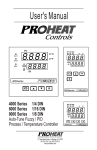
Example 2: Dual Set Point / PID
A heat treating furnace is required to harden the mold at a high temperature
( 1000 C ) for 30 minutes, then the mold is cooled down with a
programmable ramp ( 20 C / minute ) toward a lower set point ( 200 C ).
Use the dual set point / PID and ramp / dwell functions for this application.
( 1 ) Set the following parameters in the Setup menu:
FUNC= FULL
A1FN= TIMR
EIFN= SP.P2
PVMD= PV1
SPMD= MINR
( 2 ) Adjust the following parameters in the User menu:
TIME= 30.0 ( Minutes )
RAMP= 20.0 ( C/Minute )
SP1= 1000 C
SP2= 200 C
PL1= 100 ( % )
( 3 ) Set the proper values for PB1, TI1, TD1,PB2, TI2 and TD2 directly according
to the previous records. For a new system tune first PID set at SP1=800 C
and tune second PID set at SP2=400 C.
The circuit diagram is same as shown in Figure 5.14. The temperature profile
is shown as below:
C
30
minutes
40
minutes
Figure 5.16
Dual Set Point /PID Profile
1000
200
Use SP1,PID1
Use SP2,PID2
Time ( Minutes )
95
5 10 RS-485
A tile making plant has 5 production lines. Each production line is
equipped with 16 units of ZEL - 2500 to control the temperature for
the kiln. They are desirable to program the controllers and monitor the
process in the control room for the purpose of improving the quality
and productivity. A cost effective solution for the above application is
to use 80 units of ZEL - 2500 - XXXXX1 plus a SNA10B Smart
Network Adaptor and ZE - Net PC based software for this purpose.
The system is installed as shown in the following diagram.
Kiln 1
1
16
2
O1
O1
O1
O2
O2
O2
A1
A1
A1
ZESTA ZEL - 2500
TX1
ZESTA ZEL - 2500
C
TX1
TX2
ZESTA ZEL - 2500
C
TX1
TX2
Figure 5.17
RS-485 Applications
TX2 TX1
C
TX2
Control Room
Terminator, 220 ohms/0.5W
PC
( ZE - Net )
Kiln 2
Kiln 3
Kiln 4
TX1
TX2
RS-232
Kiln 5
SNA10B
65
80
66
O1
O1
O1
O2
O2
O2
A1
A1
A1
ZESTA ZEL - 2500
TX1
C
TX2
ZESTA ZEL - 2500
TX1
ZESTA ZEL - 2500
C
TX2
TX2
TX1
TX2 TX1
TX1
C
TX2
Twisted-pair wire, max. distance 1 Km
96
Setup
Enters the setup mode to configure each ZEL - 2500. Choose FULL for FUNC, 485
for COMM, RTU for PROT and select an unequal address ( ADDR ) for each unit.
Use the same values of BAUD, DATA, PARI and STOP for ZEL - 2500's, SNA10B
and ZE - Net. Also refer to Section 2-15 and Section 4-8.
Taking the advantage of ZE - Net software, the operator can monitor the process on
the PC screen, program the set point as well as other control parameters such as
PID values, down load the ramp and soak profile to the controllers, execute the
manual control or trigger an auto-tuning.....etc. , and print out a report as required.
The historical data can be saved in the floppy disc, hard disc or a CD for
permanent storage purpose.
Setup Menu
FUNC
COMM
PROT
ADDR
BAUD
DATA
PARI
STOP
97
5 11 RS-232
Suppose a chemical experiment is performed in a laboratory. And an engineer
desires to find out the relation between the chemical reaction and
temperature. He uses a ZEL - 2500 to control the temperature of the solution
under test. A testing report containing the relation between the concentration
and temperature is particularly interested.
For a single unit application it is adequate to order a ZEL - 2500 - xxxxx2 with
RS-232 communication and a ZE - Net software. By using the ZE - Net
software the temperature data can be viewed and stored in a file. The user can
program the temperature as well as other control parameters such as PID
values. He can setup the controller, down load a ramp and soak profile, also
execute the manual control or auto-tuning procedure ..... etc. The results can
be printed out or stored in a file for the future reference.
Refer to Section 2-16 for installation and Section 4-8 for setup procedure.
98
Setup Menu
FUNC
COMM
PROT
ADDR
BAUD
DATA
PARI
STOP
5 12 Retransmit
An air-conditioned room uses two units of ZEL - 2500 to control its temperature
and humidity. The temperature and humidity are required to be recorded on a
chart recorder. The interesting ranges for these two quantity are: 20 C to 30 C
and 40% RH to 60% RH. The recorder inputs accept 0 - 5 V signal.
To achieve this, set the following parameters in the Setup menu.
UNIT 1:
UNIT 2:
FUNC= FULL
COMM= 0 - 5V
AOFN=PV1
AOLO=20.0 ( C )
AOHI= 30.0 ( C )
IN1= PTDN
IN1U= C
DP1= 1-DP
SP1= 25.0
SP1L= 20.0
SP1H= 30.0
FUNC= FULL
COMM= 0 - 5V
AOFN=PV1
AOLO=40.0 ( % )
AOHI= 60.0 ( % )
IN1= 0 - 1 V (According to humidity sensor )
IN1U= PU
DP1= 1-DP
SP1= 50.0
SP1L= 40.0
SP1H= 60.0
C
O1
O1
O2
O2
A1
A1
C
ZESTA ZEL - 2500
12
%RH
C
ZESTA ZEL - 2500
13
12
13
Retransmission Output
0-5V+
+
0-5V
Figure 5.18
Retransmission Application
Chart Recorder
1. 20-30 C 2. 40-50%
SP1L and SP1H are used to limit the adjustment range of set point.
99
Chapter 6 Calibration
Do not proceed through this section unless there is a definite need to
re-calibrate the controller. Otherwise, all previous calibration data will be
lost. Do not attempt recalibration unless you have appropriate calibration
equipment. If calibration data is lost, you will need to return the controller
to your supplier who may charge you a service fee to re-calibrate the
controller.
Entering calibration mode will break the control loop. Make sure that if
the system is allowable to apply calibration mode.
Equipments needed before calibration:
(1) A high accuracy calibrator ( Fluke 5520A Calibrator recommended )
with following functions:
0 - 100 mV millivolt source with A0.005 % accuracy
0 - 10 V voltage source with A0.005 % accuracy
0 - 20 mA current source with A0.005 % accuracy
0 - 300 ohm resistant source with A0.005 % accuracy
(2) A test chamber providing 25 ZE - 50 ZE temperature range
(3) A switching network ( SW6400, optional for automatic calibration )
(4) A calibration fixture equipped with programming units ( optional for
automatic calibration )
(5) A PC installed with calibration software ZE - Net and Smart Network
Adaptor SNA10B ( optional for automatic calibration )
The calibration procedures described in the following section are a step by step
manual procedures.
Since it needs 30 minutes to warm up an unit before calibration, calibrating the
unit one by one is quite inefficient. An automatic calibration system for small
quantity as well as for unlimited quantity is available upon request.
100
Manual Calibration Procedures
Perform step 1 to enter calibration mode.
Step 1. Set the lockout DIP switch to the unlocked condition ( both switches
3 and 4 are off ).
Press both scroll and down keys and release them quickly. The
operation mode menu will appear on the display. Repeat the operation
several times until
appear on the display.
Press scroll key for at least 3 seconds , the display will show
and the unit enters calibration mode . The output 1 and output 2 use
their failure transfer values to control.
Perform step 2 to calibrate Zero of A to D converter and step 3 to
calibrate gain of A to D converter. The DIP switch is set for T/C input.
Step 2. Short terminals 9 and 10 , then press scroll key for at least 3 seconds.
DIP Switch Position
ON
The display will blink a moment and a new value is obtained.
T/C input
Otherwise, if the display didn't blink or if the obtained value is equal to
1 2 3 4
-360 or 360, then the calibration fails.
Step 3. Press scroll key until the display shows
. Send a 60mV signal
to terminals 9 and 10 in correct polarity . Press scroll key for at
least 3 seconds . The display will blink a moment and a new value is
obtained . Otherwise , if the display didn't blink or if the obtained value
is equal to -199.9 or 199.9, then the calibration fails.
Perform step 4 to calibrate voltage function ( if required ) for input 1.
Step 4. Change the DIP switch for the Voltage input. Press scroll key until
the display shows
. Send a 10 V signal to terminals 9 and
10 in correct polarity. Press scroll key for at least 3 seconds . The
display will blink a moment and a new value is obtained . Otherwise,
if the display didn't blink or if the obtained value is equal to -199.9 or
199.9 , then the calibration fails.
DIP Switch Position
ON
0 10V input
1
2
3
4
Perform both steps 5 and 6 to calibrate RTD function ( if required )
for input 1.
Step 5. Change the DIP switch for the RTD input . Press scroll key until the
display shows
. Send a 100 ohms signal to terminals 8, 9
and 10 according to the connection shown below:
DIP Switch Position
ON
RTD input
1
100 ohms
8
9
10
ZEL - 2500
2
3
4
Figure 6.1
RTD Calibration
Press scroll key for at least 3 seconds . The display will blink a
moment, otherwise the calibration fails.
101
Step 6. Press scroll key and the display will show
. Change the
ohm's value to 300 ohms .Press scroll key for at least 3 seconds.
The display will blink a moment and two values are obtained for SR1
and REF1 (last step). Otherwise, if the display didn't blink or if any
value obtained for SR1 and REF1 is equal to -199.9 or 199.9 ,
then the calibration fails.
Perform step 7 to calibrate mA function ( if required ) for input 1.
Step 7. Change the DIP switch for mA input. Press scroll key until the display
shows
.Send a 20 mA signal to terminals 9 and 10 in
correct polarity. Press scroll key for at least 3 seconds . The display
will blink a moment and a new value is obtained . Otherwise , if the
display didn't blink or if the obtained value is equal to -199.9 or 199.9,
then the calibration fails.
DIP Switch Position
ON
mA input
1
2
3
4
Perform step 8 to calibrate voltage as well as CT function ( if required )
for input 2.
Step 8. Press scroll key until the display shows
. Send a 10 V signal to
terminals 10 and 11 in correct polarity. Press scroll key for at least 3
seconds . The display will blink a moment and a new value is obtained .
Otherwise , if the display didn't blink or if the obtained value is equal
to -199.9 or 199.9 , then the calibration fails.
Perform step 9 to calibrate offset of cold junction compensation, if
required. The DIP switch is set for T/C input.
Step 9. Setup the equipments according to the following diagram for
calibrating the cold junction compensation. Note that a K type
thermocouple must be used.
DIP Switch Position
ON
TC input
1
5520A
Calibrator
K-TC
K+
K
9
10
ZEL - 2500
_
Stay at least 20 minutes in still-air
room room temperature 25 A 3 LC
The 5520A calibrator is configured as K type thermocouple output
with internal compensation. Send a 0.00 LC signal to the unit under
calibration.
102
2
3
4
Figure 6.2
Cold Junction
Calibration Setup
The unit under calibration is powered in a still-air room with
temperature 25 3 C. Stay at least 20 minutes for warming up. The
DIP Switch is located at TC input .
Perform step 1 stated above, then press scroll key until the display
shows
. Apply up/down key until value 0.00 is obtained .
Press scroll key at least 3 seconds. The display will blink a moment
and a new value is obtained . Otherwise , if the display didn't blink
or if the obtained value is equal to -5.00 or 40.00, then the calibration
fails.
Perform step 10 to calibrate gain of cold junction compensation if
required, otherwise , perform step 10N to use a nominal value for the
cold junction gain if a test chamber for calibration is not available.
Step 10. Setup the equipments same as step 9. The unit under calibration is
powered in a still-air room with temperature 50A3 ZE. Stay at least 20
minutes for warming up . The calibrator source is set at 0.00 LC with
internal compensation mode.
Perform step 1 stated above , then press scroll key until the display
shows
. Apply up/down key until value 0.0 is obtained. Press
scroll key for at least 3 seconds . The display will blink a moment and
a new value is obtained. Otherwise , if the display didn't blink or if
the obtained value is equal to -199.9 or 199.9, then the calibration
fails.
This setup is performed in a high temperature chamber, hence it is
recommended to use a computer to perform the procedures.
Step 10N. Perform step 1 stated above , then press scroll key until the display
shows
. Apply up/down key until value 0.1 is obtained.
Press scroll key for at least 3 seconds. The display will blink a moment
and the new value 0.0 is obtained. Otherwise , the calibration fails.
Caution: It is not recommended to use this step 10N, since the cold junction
gain is not able to achieve rated accuracy by this step.
Final step
Step 11. Set the DIP switch to your desired position ( refer to section 1-3 ).
Automatic Calibration Procedures
The programming port ( See Section 2-18 ) of ZEL - 2500 can be used for
automatic calibration. The equipments required for automatic calibration are
available upon request.
103
Chapter 7 Error Codes & Troubleshooting
This procedure requires access to the circuitry of a live power unit. Dangerous accidental contact with line voltage
is possible. Only qualified personnel are allowable to perform these procedures. Potentially lethal voltages are
present.
Troubleshooting Procedures :
(1) If an error message is displayed, refer to Table 7.1 to see what cause it is and apply a corrective action to the
failure unit.
(2) Check each point listed below. Experience has proven that many control problems are caused by a defective
instrument.
* Line wires are improperly connected
* No voltage between line terminals
* Incorrect voltage between line terminals
* Connections to terminals are open, missing or loose
* Thermocouple is open at tip
* Thermocouple lead is broken
* Shorted thermocouple leads
* Short across terminals
* Open or shorted heater circuit
* Open coil in external contactor
* Burned out line fuses
* Burned out relay inside control
* Defective solid-state relays
* Defective line switches
* Burned out contactor
* Defective circuit breakers
(3) If the points listed on the above chart have been checked and the controller does not function properly, it is
suggested that the instrument be returned to the factory for inspection.
Do not attempt to make repairs without qualified engineer and proper technical information . It may create
costly damage. Also , it is advisable to use adequate packing materials to prevent damage in transportation.
(4) Dismantle the controller according to Figure 7.1 .
Refer to Table 7.2 for some probable causes and actions.
Press both sides of the latch located on rear
terminal block.Hold tightly and remove the
terminal block from the housing.
Expand the rear edge of the housing by
using a tool. Pull out the PCB from the housing.
Figure 7.1
Dismantling the Controller
O1
O2
A1
ZESTA ZEL - 2500
104
C
Table 7.1 Error Codes and Corrective Actions
Error Display
Code Symbol
1
2
3
Error Description
Illegal setup values been used: PV1 is used for both PVMD
and SPMD. It is meaningless for control.
Illegal setup values been used: PV2 is used for both PVMD
and SPMD. It is meaningless for control
Illegal setup values been used: P1-2 or P2-1 is used for
PVMD while PV1 or PV2 is used for SPMD. Dependent
values used for PV and SV will create incorrect result
of control
Corrective Action
Check and correct setup values of PVMD and SPMD. PV
and SV can't use the same value for normal control
Same as error code 1
Check and correct setup values of PVMD and SPMD.
Difference of PV1 and PV2 can't be used for PV while PV1
or PV2 is used for SV
Illegal setup values been used: Before COOL is used for
OUT2, DIRT ( cooling action ) has already been used for
OUT1, or PID mode is not used for OUT1 ( that is PB1 or
PB2 = 0, and TI1 or TI2 = 0 )
Check and correct setup values of OUT2, PB1, PB2, TI1,
TI2 and OUT1. IF OUT2 is required for cooling control, the
control should use PID mode ( PB = 0, TI = 0 ) and OUT1
should use reverse mode (heating action), otherwise, don't
use OUT2 for cooling control
7
Illegal setup values been used: unequal IN1U and IN2U or
unequal DP1 and DP2 while P1-2 or P2-1 is used for PVMD
or, PV1 or PV2 is used for SPMD or, P1.2.H, P1.2.L, D1.2.H
or D1.2.L are used for A1FN or A2FN.
Illegal setup values been used: OUT2 select =AL2 but
A2FN select NONE
Illegal setup values been used: Dwell timer (TIMR) is
selected for both A1FN and A2FN.
10
Communication error: bad function code
Check and correct setup values of IN1U, IN2U, DP1, DP2,
PVMD, SPMD, A1FN or A2FN. Same unit and decimal point
should be used if both PV1 and PV2 are used for PV, SV,
alarm 1 or alarm 2.
Check and correct setup values of OUT2 and A2FN. OUT2
will not perform alarm function if A2FN select NONE.
Check and correct setup values of A1FN and A2FN. Dwell
timer can only be properly used for single alarm output.
Correct the communication software to meet the protocol
requirements.
11
Communication error: register address out of range
Don't issue an over-range register address to the slave.
12
Communication error: access a non-existent parameter
Don't issue a non-existent parameter to the slave.
14
Communication error: attempt to write a read-only data
Don't write a read-only data or a protected data to the slave.
15
Communication error: write a value which is out of range to
Don't write an over-range data to the slave register.
a register
1.The PID values obtained after auto-tuning procedure are
out of range. Retry auto-tuning.
2.Don't change set point value during auto-tuning
procedure.
Fail to perform auto-tuning function
3. Don't change Event input state during auto-tuning
procedure.
4.Use manual tuning instead of auto-tuning.
4
5
6
26
29
EEPROM can't be written correctly
Return to factory for repair.
38
Input 2 ( IN2 ) sensor break, or input 2 current below 1 mA
if 4-20 mA is selected, or input 2 voltage below 0.25V if
1 - 5V is selected
Replace input 2 sensor.
39
Input 1 ( IN1 ) sensor break, or input 1 current below 1 mA
if 4-20 mA is selected, or input 1 voltage below 0.25V if
1 - 5V is selected
Replace input 1 sensor.
40
A to D converter or related component(s) malfunction
Return to factory for repair.
105
Table 7.2 Common Failure Causes and Corrective Actions
Symptom
Probable Causes
Corrective Actions
- No power to instrument
- Power supply defective
- LED display or LED lamp defective
- Related LED driver defective
- Clean contact area on PCB
- Replace keypads
- Check power line connections
- Replace power supply board
- Replace LED display or LED lamp
- Replace the related transistor or IC chip
4) Display Unstable
- Analog portion or A-D converter defective
- Thermocouple, RTD or sensor defective
- Intermittent connection of sensor wiring
- Replace related components or board
- Check thermocouple, RTD or sensor
- Check sensor wiring connections
5) Considerable error in temperature
indication
- Wrong sensor or thermocouple type, wrong
input mode selected.
- Analog portion of A-D converter defective
- Check sensor or thermocouple type and if
proper input mode was selected
- Replace related components or board
6) Display goes in reverse direction
( counts down scale as process warms )
- Reversed input wiring of sensor
- Check and correct
- No heater power ( output ), incorrect output
device used
- Output device defective
- Open fuse outside of the instrument
- Output device shorted, or power service
shorted
- Check output wiring and output device
- Replace output device
- Replace output fuse
9) Control abnormal or operation incorrect
- CPU or EEPROM ( non-volatile memory )
defective. Key switch defective
- Incorrect setup values
- Check and replace
- Read the setup procedure carefully
10) Display blinks; entered values change
by themselves
- Electromagnetic interference ( EMI ), or
Radio Frequency interference ( RFI )
- EEPROM defective
1) Keypad no function
2) LED's will not light
3) Some segments of the display or
LED lamps not lit or lit erroneously.
7) No heat or output
8) Heat or output stays on but indicator
reads normal
106
-Bad connection between PCB & keypads
- Check and replace
- Suppress arcing contacts in system to
eliminate high voltage spike sources.
Separate sensor and controller wiring from
" dirty " power lines, ground heaters
- Replace EEPROM
Chapter 8 Specifications
Power
90 264 VAC, 47 63 Hz, 15VA, 7W maximum
11 26 VAC / VDC, 15VA, 7W maximum
Input 2
Resolution : 18 bits
Input 1
Sampling Rate : 1.66 times / second
Maximum Rating : -2 VDC minimum, 12 VDC maximum
Resolution : 18 bits
Temperature
Effect : A1.5 uV/ ZE
Sampling Rate : 5 times / second
Common Mode Rejection Ratio ( CMRR ): 120dB
Maximum Rating : -2 VDC minimum, 12 VDC maximum
Normal Mode Rejection Ratio ( NMRR ): 55dB
( 1 minute for mA input )
Temperature Effect : A1.5 uV/ ZE for all inputs except
Sensor Break Detection :
mA input
below 0.25V for 1 - 5V input,
A3.0 uV/ ZE for mA input
unavailable
for other inputs.
Sensor Lead Resistance Effect :
T/C: 0.2uV/ohm
Sensor Break Responding Time : 0.5 second
3-wire RTD: 2.6 LC/ohm of resistance difference of two
leads
2-wire RTD: 2.6 LC/ohm of resistance sum of two leads
Characteristics:
Burn-out Current : 200 nA
Common Mode Rejection Ratio ( CMRR ): 120dB
Input
Accuracy
Range
Type
Normal Mode Rejection Ratio ( NMRR ): 55dB
Impedance
@ 25 C
A2 %
Sensor Break Detection :
Sensor open for TC, RTD and mV inputs,
265 K
CT94-1 0 50.0 A of Reading
below 1 mA for 4-20 mA input,
A0.2 A
below 0.25V for 1 - 5 V input,
-1.3V 11.5V A0.05 %
265 K
V
unavailable for other inputs.
Sensor Break Responding Time :
Within 4 seconds for TC, RTD and mV inputs,
0.1 second for 4-20 mA and 1 - 5 V inputs.
Characteristics:
Input
Accuracy
Type
Range
@ 25 C Impedance
-120 C 1000 C
J
A2 LC
2.2 M
( -184 F 1832 F )
-200 C 1370 C
K ( -328 F 2498 F ) A2 LC
2.2 M
-250 C 400 C
A2 LC
T
2.2 M
( -418 F 752 F )
-100 C 900 C
A2 LC
E
2.2 M
( -148 F 1652 F )
B
R
S
N
L
PT100
( DIN )
PT100
( JIS )
mV
A2 LC
0 C 1820 C
( 200 C
( - 32 F 3308 F )
1820 C )
0 C 1767.8 C
A2 LC
( - 32 F 3214 F )
0 C 1767.8 C
A2 LC
( - 32 F 3214 F )
-250 C 1300 C
A2 LC
( -418 F 2372 F )
-200 C 900 C
( -328 F 1652 F ) A2 LC
-210 C 700 C
A0.4 LC
( -346 F 1292 F )
-200 C 600 C
A0.4 LC
( -328 F 1112 F )
A0.05 %
-8mV 70mV
2.2 M
2.2 M
Input 3 (Event Input )
Logic Low : -10V minimum, 0.28V maximum.
Logic High : Open or 0.32V minimum, 10V maximum
External pull-down Resistance : 200 K maximum
External pull-up Resistance : not necessary
Functions : Select second set point and/or PID,
reset alarm 1 and/or alarm 2,
disable output 1 and/or output 2,
remote lockout.
Output 1 / Output 2
Relay Rating : 2A/240 VAC, life cycles 200,000 for
resistive load
Pulsed Voltage : Source Voltage 5V,
current limiting resistance 66 .
Linear Output Characteristics
Span
Tolerance
20-21 mA
20-21 mA
Load
Capacity
500 max.
500 max.
2.2 M
4-20 mA
0-20 mA
Zero
Tolerance
3.8-4 mA
0 mA
2.2 M
0 5V
0V
5
5.25 V
10 K
min.
1 5V
0.95 1 V
5
5.25 V
10 K
min.
0 10 V
0V
10 10.5 V 10 K
min.
2.2 M
1.3 K
Type
1.3 K
2.2 M
mA
-3mA 27mA
A0.05 %
70.5
V
-1.3V 11.5V
A0.05 %
302 K
107
Linear Output
Resolution : 15 bits
Output Regulation : 0.01 % for full load change
Output Settling Time : 0.1 sec. ( stable to 99.9 % )
Isolation Breakdown Voltage : 1000 VAC
Temperature Effect : A0.0025 % of SPAN / LC
Triac ( SSR ) Output
Rating : 1A / 240 VAC
Inrush Current : 20A for 1 cycle
Min. Load Current : 50 mA rms
Max. Off-state Leakage : 3 mA rms
Max. On-state Voltage : 1.5 V rms
Insulation Resistance : 1000 Mohms min. at 500 VDC
Dielectric Strength : 2500 VAC for 1 minute
DC Voltage Supply Characteristics ( Installed at Output 2 )
Type Tolerance Max. Output Ripple
Current Voltage
0.2 Vp-p
20 V A0.5 V
25 mA
0.1 Vp-p
40 mA
12 V A0.3 V
5 V A0.15 V
80 mA
Isolation
Barrier
500 VAC
500 VAC
0.05 Vp-p 500 VAC
Resolution : 15 bits
Accuracy : A0.05 % of span A0.0025 %/ LC
Load Resistance :
0 - 500 ohms ( for current output )
10 K ohms minimum ( for voltage output )
Output Regulation : 0.01 % for full load change
Output Settling Time : 0.1 sec. (stable to 99.9 % )
Isolation Breakdown Voltage : 1000 VAC min.
Integral Linearity Error : A0.005 % of span
Temperature Effect : A0.0025 % of span/ LC
Saturation Low : 0 mA ( or 0V )
Saturation High : 22.2 mA ( or 5.55V, 11.1V min. )
Linear Output Range :0-22.2mA(0-20mA or 4-20mA)
0-5.55V ( 0 - 5V, 1 - 5V )
0 - 11.1 V ( 0 - 10V )
User Interface
Dual 4-digit LED Displays : Upper 0.4" ( 10 mm ),
Lower 0.3 " ( 8 mm )
Keypad : 3 keys
Programming Port :For automatic setup, calibration
and testing
Communication Port : Connection to PC for
supervisory control
Alarm 1/ Alarm 2
Control Mode
Alarm 1 : 5V DC logic output, max. source current 100mA,
Output 1 : Reverse ( heating ) or direct ( cooling )
short circuit unprotected.
action
Alarm 2 Relay : Form A, Max. rating 2A/240VAC,
Output 2 : PID cooling control, cooling P band 1~
life cycles 200,000 for resistive load.
255% of PB
Alarm Functions : Dwell timer,
ON-OFF : 0.1 - 100.0 ( LF ) hysteresis control
Deviation High / Low Alarm,
( P band = 0 )
Deviation Band High / Low Alarm,
P or PD : 0 - 100.0 % offset adjustment
PV1 High / Low Alarm,
PID : Fuzzy logic modified
PV2 High / Low Alarm,
Proportional band 0.1 ~ 900.0 LF.
PV1 or PV2 High / Low Alarm,
Integral time 0 - 1000 seconds
PV1-PV2 High / Low Alarm,
Derivative time 0 - 360.0 seconds
Loop Break Alarm,
Cycle Time : 0.1 - 100.0 seconds
Sensor Break Alarm.
Manual Control : Heat (MV1) and Cool (MV2)
Alarm Mode : Normal, Latching, Hold, Latching / Hold.
Auto-tuning : Cold start and warm start
Dwell Timer : 0 - 6553.5 minutes
Self-tuning : Select None and YES
Failure Mode : Auto-transfer to manual mode while
sensor break or A-D converter damage
Data Communication
Sleep
Mode
: Enable or Disable
Interface : RS-232 ( 1 unit ), RS-485 ( up to 247 units )
Ramping
Control
: 0 - 900.0 LF/minute or
Protocol : Modbus Protocol RTU mode
0 - 900.0 LF/hour ramp rate
Address : 1 - 247
Power
Limit
:
0
100
% output 1 and output 2
Baud Rate : 0.3 ~ 38.4 Kbits/sec
Pump
/
Pressure
Control
: Sophisticated functions
Data Bits : 7 or 8 bits
provided
Parity Bit : None, Even or Odd
Remote
Set
Point
:
Programmable
range for voltage
Stop Bit : 1 or 2 bits
or
current
input
Communication Buffer : 50 bytes
Differential Control : Control PV1-PV2 at set point
Analog Retransmission
Functions : PV1, PV2, PV1-PV2, PV2-PV1, Set Point,
Digital Filter
MV1, MV2, PV-SV deviation value
Function : First order
Output Signal : 4-20 mA, 0-20 mA, 0 - 1V, 0 - 5V,
Time Constant : 0, 0.2, 0.5, 1, 2, 5, 10, 20, 30, 60
1 - 5V, 0 - 10V
seconds programmable
108
Environmental & Physical
Operating Temperature : -10 C to 50 C
Storage Temperature : -40 C to 60 C
Humidity : 0 to 90 % RH ( non-condensing )
Insulation Resistance : 20 Mohms min. ( at 500 VDC )
Dielectric Strength : 2000 VAC, 50/60 Hz for 1 minute
Vibration Resistance : 10 - 55 Hz, 10 m/s2for 2 hours
Shock Resistance : 200 m/s2 ( 20 g )
Moldings : Flame retardant polycarbonate
Dimensions :50mm(W) X 26.5mm(H) X 110.5mm(D),
98.0 mm depth behind panel
Weight : 120 grams
Approval Standards
Safety : UL873 ( 11'th edition, 1994 )
CSA C22.2 No. 24-93
EN61010-1 ( IEC1010-1 )
Protective Class :
NEMA 4X ( IP65 ) front panel, indoor use,
IP 20 housing and terminals
EMC:
EN61326
109
A 1 Menu Existence Conditions
Menu Existence Conditions Table
Menu
Parameter
Notation
SP1
Exists unconditionally
TIME
Exists if A1FN selects TIMR or A2FN selects TIMR
A1SP
Exists if A1FN selects PV1H, PV1L, PV2H, PV2L, P12H, P12L, D12H or D12L
A1DV
Exists if A1FN selects DEHI, DELO, DBHI, or DBLO
A2SP
Exists if A2FN selects PV1H, PV1L, PV2H, PV2L, P12H, P12L, D12H or D12L
A2DV
Exists if A2FN selects DEHI, DELO, DBHI, or DBLO
RAMP
Exists if SPMD selects MINR or HRR
OFST
Exists if TI1 is used for control (depends on Event input and EIFN selection) but TI1= 0 and
PB1=0 or if TI2 is used for control (depends on Event input and EIFN selection) but TI2= 0
and PB2=0
REFC
Exists if SPMD selects PUMP
SHIF
PB1
User
Menu
TI1
TD1
CPB, DB
Exists unconditionally
Exists if PB1= 0
Exists if OUT2 select COOL
SP2
Exists if EIFN selects SP2 or SPP2, or if SPMD selects PUMP
PB2
Exists if EIFN selects PID2 or SPP2
TI2
TD2
110
Existence Conditions
Exists if EIFN selects PID2 or SPP2 provided that PB2= 0
O1HY
If PID2 or SPP2 is selected for EIFN, then O1HY exists if PB1= 0 or PB2 = 0. If PID2 or SPP2
is not selected for EIFN, then O1HY exists if PB1= 0
A1HY
Exists if A1FN selects DEHI, DELO, PV1H, PV1L, PV2H, PV2L, P12H, P12L, D12H, or D12L
A2HY
Exists if A2FN selects DEHI, DELO, PV1H, PV1L, PV2H, PV2L, P12H, P12L, D12H, or D12L
PL1
If PID2 or SPP2 is selected for EIFN, then PL1 exists if PB1= 0 or PB2 = 0. If PID2 or SPP2
is not selected for EIFN, then PL1 exists if PB1= 0
PL2
Exists if OUT2 selects COOL
Menu Existence Conditions Table ( continued 2/3 )
Menu
Parameter
Notation
Existence Conditions
FUNC
Exists unconditionally
COMM
Exists if FUNC selects FULL
PROT
ADDR
BAUD
DATA
Exists if COMM selects 485 or 232
PARI
STOP
AOFN
AOLO
AOHI
Exists if COMM selects 4-20, 0-20, 0-1V, 0-5V, 1-5V, or 0-10
Exists if COMM selects 4-20, 0-20, 0-1V, 0-5V, 1-5V, or 0-10 and AOFN is not MV1 and MV2
IN1
IN1U
Setup
Menu
Exists unconditionally
DP1
IN1L
IN1H
IN2
Exists if IN1selects 4-20, 0-20, 0-1V, 0-5V, 1-5V, or 0-10
Exists if FUNC selects FULL
IN2U
DP2
IN2L
Exists if IN2 selects 4-20, 0-20, 0-1V, 0-5V, 1-5V, or 0-10
IN2H
OUT1
O1TY
CYC1
Exists unconditionally
O1FT
OUT2
O2TY
CYC2
Exists if OUT2 selects COOL
O2FT
111
Menu Existence Conditions Table ( continued 3/3 )
Menu Parameter
Notation
Existence Conditions
A1FN
Exists unconditionally
A1MD
Exists if A1FN selects DEHI, DELO, DBHI, DBLO, PV1H, PV1L, PV2H, PV2L, P12H, P12L,
D12H, D12L, LB or SENB
A1FT
Exists if A1FN is not NONE
A2FN
Exists unconditionally
A2MD
Exists if A2FN selects DEHI, DELO, DBHI, DBLO, PV1H, PV1L, PV2H, PV2L, P12H, P12L,
D12H, D12L, LB or SENB
A2FT
Exists if A2FN is not NONE
EIFN
PVMD
Setup
Menu
Exists if FUNC selects FULL
FILT
SELF
SLEP
SPMD
SP1L
SP1H
SP2F
Exists unconditionally
Exists if FUNC selects FULL
Exists unconditionally
Exists if EIFN selects SP2 or SPP2, or if SPMD selects PUMP
SEL1
SEL2
SEL3
SEL4
SEL5
112
Exists unconditionally
A 2 Factory Menu Description
Parameter Display
Notation Format
Parameter Description
Range
Current Error Code
Program Identification Code Contains Program
Number and Version Number
Contains Lockout Status Code and Current System
Mode
Command Password
Low:
0
High: 40
Low:
0
High: 15.99
Low:
0
High: 3.5
Low:
0
High: 65535
JOB
Job Password
Low:
0
High: 65535
DRIF
Warm-up Drift Calibration Factor
Low:
-5.0 C
High: 5.0 C
AD0
A to D Zero Calibration Coefficient
Low:
-360
High: 360
ADG
A to D Gain Calibration Coefficient
Low:
-199.9
High: 199.9
V1G
Voltage Input 1 Gain Calibration Coefficient
Low:
-199.9
High: 199.9
CJTL
Low:
-5.00 LC
High: 40.00 LC
CJG
Cold Junction Low Temperature Calibration
Coefficient
Cold Junction Gain Calibration Coefficient
Low:
-199.9
High: 199.9
REF1
Reference Voltage 1 Calibration Coefficient for RTD 1
Low:
-199.9
High: 199.9
SR1
Serial Resistance 1 Calibration Coefficient for RTD 1
Low:
-199.9
High: 199.9
mA Input 1 Gain Calibration Coefficient
Low:
-199.9
High: 199.9
V2G
Voltage Input 2 Gain Calibration Coefficient
Low:
-199.9
High: 199.9
SIG1
Point 1 Signal Value of Special Sensor
Low:
-19999
High: 45536
IND1
Point 1 Indication Value of Special Sensor
Low:
-19999
High: 45536
SIG2
Point 2 Signal Value of Special Sensor
Low:
-19999
High: 45536
IND2
Point 2 Indication Value of Special Sensor
Low:
-19999
High: 45536
SIG3
Point 3 Signal Value of Special Sensor
Low:
-19999
High: 45536
IND3
Point 3 Indication Value of Special Sensor
Low:
-19999
High: 45536
SIG4
Point 4 Signal Value of Special Sensor
Low:
-19999
High: 45536
IND4
Point 4 Indication Value of Special Sensor
Low:
-19999
High: 45536
SIG5
Point 5 Signal Value of Special Sensor
Low:
-19999
High: 45536
IND5
Point 5 Indication Value of Special Sensor
Low:
-19999
High: 45536
SIG6
Point 6 Signal Value of Special Sensor
Low:
-19999
High: 45536
IND6
Point 6 Indication Value of Special Sensor
Low:
-19999
High: 45536
SIG7
Point 7 Signal Value of Special Sensor
Low:
-19999
High: 45536
IND7
Point 7 Indication Value of Special Sensor
Low:
-19999
High: 45536
SIG8
Point 8 Signal Value of Special Sensor
Low:
-19999
High: 45536
IND8
Point 8 Indication Value of Special Sensor
Low:
-19999
High: 45536
SIG9
Point 9 Signal Value of Special Sensor
Low:
-19999
High: 45536
IND9
Point 9 Indication Value of Special Sensor
Low:
-19999
High: 45536
TYPE
Signal Type of Special Sensor
Low:
0
High: 3
DATE
Manufacturing Date of Product
Low:
0
High: 3719
Serial Number of Product
Low:
1
High: 999
EROR
PROG
MODE
CMND
MA1G
NO
Default
Value
These parameters are available only if IN1 selects SPEC.
113
Parameter Display
Notation Format
Parameter Description
Range
Default
Value
HOUR
Working Hour Value
Low:
0
High: 65535 Hours
HRLO
Fractional Hour Value
Low:
0
High: 0.9 Hour
ERR1
Historical Error Record 1
Low:
0
High: FFFF
0
ERR2
Historical Error Record 2
Low:
0
High: FFFF
0
DELI
ASCII Input Delimiter
Low:
0000
High: 007F
000A
BPL1
OUT1 Bumpless Transfer Value
Low:
0
High: 100.00 %
BPL2
OUT2 Bumpless Transfer Value
Low:
0
High: 100.00 %
CJCL
Sense Voltage of Cold Junction Calibration Low
Low:
31.680
High: 40.320 mV
114
A 3 Glossary
Abosolute zero: The lowest theoretical temperature. At
absolute zero, a body would have no molecular motion
of heat energy. Absolute zero is the zero point on the
Rankine and Kelvin scale. (-273.15 C or -459.67 F)
AC: Alternating Current; an electric current that reverses
direction at regularly occurring intervals.
Accuracy
Calibration accuracy: The potential error of a device
compared to a physical constant or agency
standard.
Control accuracy: Maintaining a process at the desired
setting. The errors or combination of errors in the
entire system including the sensor, control, power,
load and design inefficiencies affect control accuracy.
Display accuracy: The amount of potential error
between a measured value and the control's
displayed value.
Set point accuracy: The potential error between a
measured value and the control setting.
Alarm: A control condition or function, indicating that the
process is a predetermined amount above or below the
set point.
Alpha ( ): The average percent change in resistance per
degree of a pure metal resistance device between 0
and 100 C. Usually designated by the Greek letter
alpha, with units of ohm/ohm/ C. The common alpha
for a platinum RTD is 0.00385 ohm/ohm/ C.
Automatic reset (Integral): The integral function of a
control that automatically compensates for the
difference between the set point and the actual process
temperature. A signal moves the proportional band
up or down to correct for the droop or offset error.
Automatic tuning (of control parameters): A control that
calculates the optimum PID parameters with a built-in
software algorithm to eliminate manual tuning efforts.
AWG: American Wire Gauge.
Bandwidth: A symmetrical region around the set point in
which proportional control occurs.
Baud rate: In serial communications, the rate of
information transfer in bits per second.
Blackbody: A theoretical object that radiates the maximum
amount of energy at a given temperature, and absorbs
all the energy incident upon it. A blackbody is not
necessarily black. (The name blackbody was chosen
because the color black is defined as the total
absorption of light [energy].)
Boiling point: The temperature at which a substance in
the liquid phase transforms to the gaseous phase;
commonly refers to the boiling point of water which is
100 C (212 F) at sea level.
Btu: British Thermal Unit. The quantity of thermal energy
required to raise one pound of water 1 F at or near its
maximum density (39.1 F).
Ambient compensation: The design of an instrument such
Bumpless transfer: The smooth, automatic transition from
that changes in ambient temperature do not affect the
readings of the instrument.
automatic control (closed loop) to manual control (open
loop). The control output is maintained during the
transfer.
Ambient temperature: The average or mean temperature
Burst proportioning: A fast-cycling output form on a time
of the surrounding air which comes in contact with the
equipment and instruments under test.
Ampere (amp): A unit used to define the rate of flow of
electricity (current) in a circuit; units are one coulomb
(6.25 x 10 18electrons) per second.
Analog indication: A meter with graduated scale and a
pointer that moves to indicate process condition.
Analog output: A voltage or current signal that is a
continuous function of the measure parameter.
Analog set point: Potentiometer adjustment of the control
setting.
ANSI: American National Standards Institute
Anti-reset windup: This is a feature in a three-mode PID
controller which prevents the integral (auto reset) circuit
from functioning when the temperature is outside the
proportional band.
ASME: American Society of Mechanical Engineers.
proportioning controller (typically adjustable from .2 to
4 seconds) used in conjunction with a solid state relay
to prolong the life of heaters by minimizing thermal
stress.
Calender-van Dusen equation: An equation that defines
the resistance-temperature value of any pure metal that
takes the form of RT= RO(1 + AT + BT 2 ) for values
between the ice point (0 C) and the freezing point of
antimony (630.7 C) and the form RT= RO[1 + AT +
BT 2+ C( T-100)T 2] between the oxygen point (-183.0
C) and the ice point (0 C).
Calibration: The process of adjusting an instrument so that
the indication is accurate compared to the actual value.
Calorie: The quantity of thermal energy required to raise
one gram of water 1 C at 15 C.
Cascade: Control in which the output of a secondary or
inner control loop is the set point for a primary or outer
loop. The primary loop, in turn, determines the control
action.
ASTM: American Society for Testing and Materials.
115
CE: A mark that designates compliance with European
Union (EU) requirements for products sold in Europe.
Celsius: (Centigrade) A temperature scale with 0 C
defined as the ice point and 100 C as the boiling point
of water at sea level.
Cfm: The volumetric flow rate of a liquid or gas in cubic
feet per minute.
Chatter: The rapid cycling on and off of a relay in a control
process due to insufficient bandwidth in the controller.
Closed loop control: A control system in which process
temperature changes are detected by a sensor. The
feedback from the sensor allows the control make
adjustments for accurate system regulation.
Cold junction compensation: A temperature sensitive
device that prevents changes in the ambient
temperature from affecting the cold junction of a
thermocouple.
Common mode rejection ratio: The ability of an instrument
to reject interference from a common voltage at the
input terminals with relation to ground. Expressed in dB
(decibels).
Control loop: The basic control loop of any automatic
control system consists of:
1) variable (process)
2) sensor
3) error detector (of control)
4) control
5) final control element (relay, SSR, SCR)
6) temperature indication
Control mode: The method in which the control restores
the system temperature to set point. On/Off,
proportional, and PID are the most common control
modes.
CT: Current Transformer
Current proportioning: A 4-20 milliamp (typical) current
output which provides a current proportional to the
amount of control required.
Current transformer: A transformer, intended for measuring
purposes, designed to generate a current at its
secondary winding which is proportional to the current
at the primary winding.
Cycle time: The time usually expressed in seconds for a
controller to complete one on/off cycle.
Data logging: Recording a process variable over an
extended period of time.
DC: Direct Current; An electric current flowing in one
direction and constant in value.
116
Dead band: 1. For chart recorders: the minimum change
of input signal required to cause a deflection in the
pen position. 2. For temperature controllers: the
temperature band where heat is turned off upon rising
temperature and turned on upon falling temperature
expressed in degrees. The area where no heating (or
cooling) takes place.
Default parameters: The parameters, or programmed
instructions, permanently stored in microprocessor
software to provide a data base.
Derivative: (See Rate)
Deviation: The difference between the value of the
controlled variable and the value at which it is being
controlled.
Deviation alarm: An offset value that follows the set point.
If the set point is 350 F and the Deviation alarm value
is +20 F, the alarm value would be 350 F plus 20 F
(or 370 F), See Process alarm.
Dielectric strength: An amount of voltage that an insulating
material can withstand before an electrical breakdown
occurs.
Differential: In an on/off control, the temperature difference
expressed in degrees between where the control
switches off and the control switches on.
Differential control: A controller can control one process
in relation to the difference of a second process.
DIN: Deutsche Industrial Norms. A German agency that
sets engineering and dimensional standards that now
has worldwide recognition.
Drift: A change in a value over a long period due to
changes in factors such as ambient temperature, time
or line voltage.
Droop: In time proportioning controls, the difference in
temperature between the set point and where the
system temperature stabilizes. Corrected by automatic
or manual reset.
Dual output: The primary output will regulate the process
temperature. A secondary output will be utilized for
process cooling or as an alarm.
Duty cycle: Percentage of "load ON time" relative to total
cycle time.
Efficiency: The amount of useful output versus energy
input.
Electrical interference: Electrical noise induced upon the
signal wires that obscures the wanted information
signal.
Electromagnetic Compatibility (EMC): A system meets
three requirements: 1. It does not cause interference
with other systems, 2. It is not susceptible to emissions
from other systems and 3. It does not cause
interference with itself.
Electromagnetic interference (EMI): An electrical and
magnetic noise which can be generated when
switching inductive devices, lightning, radio wave
radiation, electrostatic discharge etc.
emf: Electromotive force. A rise in (electrical) potential
energy. The principal unit is the volt.
Emissivity: The ratio of energy emitted by an object to
the energy emitted by a blackbody at the same
temperature. The emissivity of an object depends
upon its material and surface texture; a polished metal
surface can have an emissivity around 0.2, and a
piece of wood can have an emissivity around 0.95.
Endothermic: Absorbs heat. A process is said to be
endothermic when it absorbs heat.
Error: The difference between the correct or desired
value and the actual reading or value taken.
Event input: A programmable On/Off input used to signal
peripheral equipment or a process.
Event output: A programmable On/Off output used to
signal peripheral equipment or a process.
Exothermic: Gives off heat. A process is said to be
exothermic when it releases heat.
Fahrenheit: A temperature scale with 32 F defined as the
ice point and 212 F as the boiling point of water at sea
level.
Filter: A low pass filter designed to minimize display
fluctuations.
Flow rate: speed or velocity of fluid movement.
FM: Factory Mutual Research Corp. An organization
which sets industrial safety standards.
FM-approved: An instrument that meets a specific set of
specifications established by Factory Mutual Research
Corp.
Form A: Single Pole Single Throw relay that only utilizes
the N.O. and common contacts. These contacts close
when the relay coil is energized. The contacts open
when power is removed from the control.
Form B: Single Pole Single Throw relay that only utilizes
the N.C. and common contacts. These contacts will
open when the relay coil is energized. The contacts will
close when power is removed from the control.
Form C: Single Pole Double Throw. Utilizes the N.O., N.C.
and common contacts. The user has the option of
wiring for a Form A or Form B contact. Refer to the Form
A and Form B above for more information.
Fpm: Flow velocity in feet per minute.
Fps: Flow velocity in feet per second.
Freezing point: The temperature at which the substance
goes from the liquid phase to the solid phase.
Frequency: The number or event occurrences or cycles
over a specified period of time.
Fuse: A device that interrupts power in a circuit when an
overload occurs.
Fuzzy logic: An artificial intelligence technique that allows
control decisions to be made upon approximate or
incomplete information. Fuzzy logic is a continuous
decision making function that can prevent initial
overshoot and set point differentials.
Gain: The amount of amplification used in an electrical
circuit.
GIGA: The prefix for one billion (G).
Gph: The volumetric flow rate in gallons per hour.
gpm: The volumetric flow rate in gallons per minute.
Ground: 1. The electrical neutral line having the same
potential as the surrounding earth. 2. The negative
side of dc power supply. 3. Reference point for an
electrical system.
Grounded junction: A thermocouple junction in which the
sheath and conductors are welded together forming a
completely sealed integrated junction.
Heat: Thermal energy expressed in Calories, Btu's or
Joules.
Heat of fusion: The amount of energy required to change
one pound of a material from a solid to a liquid without
an increase in temperature. Expressed in Btu/lb.
Heat of vaporization: The amount of energy required to
change one pound of a material from a liquid to a vapor
without an increase in temperature. Expressed in Btu/lb.
Heat sink: 1. Thermodynamic. A body which can absorb
thermal energy. 2 Practical. A finned piece of metal
used to dissipate the heat of solid state components
mounted on it.
Heat transfer: The process of thermal energy flowing
from a body of high energy to a body of low energy.
Means of transfer are: Conduction, the two bodies in
contact; Convection, a form of conduction where the
two bodies in contact are of different phases, i.e; solid
and gas; Radiation, all bodies emit infrared radiation
Heat treating: A process for treating metals where heating
to a specific temperature and cooling at a specific rate
changes the properties of the metal.
Hertz (Hz): Unit in which frequency is expressed.
Synonymous with cycles per second.
117
Hi-Pot test : To apply a high voltage to an electrical
conductor to test the surrounding insulation.
Hysteresis: In ON/OFF control, the temperature change
necessary to change the output from full ON to full OFF.
Hunting: Oscillation or fluctuation of process temperature
between set point and process variable.
IAE: Integrated absolute error
Ice point: The temperature at which pure water freezes.
0 C, 32 F, 273.16K.
IE: Integrated error
Impedance: The total opposition in a circuit to the flow of
electrical current. Measured in ohms and represented
by "Z".
Infrared: Or radiation is the exchange of energy by
electromagnetic waves. The infrared spectrum extends
from the deep red end of the visible spectrum to the
microwave region of the radio spectrum, the portion
adjacent to the visible spectrum is of importance to
heating. Radiant heat transfer can be very efficient in
directing energy from the heat source to an object.
Integral: (See Automatic Reset).
Interchangeability error: A measurement error that can
occur if two or more probes are used to make the
same measurement. It is caused by a slight variation
in characteristics of different probes.
Intrinsically safe: An instrument which will not produce
any spark or thermal effects under normal or abnormal
conditions that will ignite a specified gas mixture.
IPTS-68: International Practical Temperature Scale of
1968. Fixed points in thermometry set by the 1968
General Conference of Weights and Measures.
Kilo: The prefix for one thousand (K).
Kilowatt (kw): 1000 watts or 3412Btu per hour.
Lag: 1. A time delay between the output of a signal and
the response of the instrument to which the signal is
sent. 2. A time relationship between two waveforms
where a fixed reference point on one wave occurs
after the same point of the reference wave.
Least Significant Digit (LSD): The digit farthest to the right
in a display.
Linearity: The deviation of an instrument's response from
a straight line.
Load: The electrical demand of a process expressed as
power (watts), current (amps) or resistance (ohms).
Manual reset: The adjustment on a proportional control
which shifts the proportional band in relation to the set
point to eliminate droop of offset errors.
Maximum operating temperature: The maximum
temperature at which an instrument or sensor can be
safely operated.
Maximum power rating: The maximum power in watts
that a device can safely handle.
Measuring junction: The thermocouple junction referred
to as the hot junction that is used to measure an
unknown temperature.
Mechanical relay: An electromechanical device that
completes or breaks a circuit by opening or closing
electrical contacts.
Mega: The prefix for one million (M) (106 ).
Melting point: The temperature at which a substance
transforms from a solid phase to a liquid phase.
Mico: The prefix for one millionth (10-6 ).
-6
ISA: Instrument Society of America.
Microamp: 10 amps (one millionth of an amp).
ISE: Integrated squared error
Micron: 10-6 meters (one millionth of a meter).
Isolation: Electrical Separation
Microprocessor: The central processing unit (CPU) that
Isothermal: A process or area that maintains a constant
temperature.
ITS-90: International Temperature Scale of 1990
Joule : The basic unit of thermal energy. 1 Joule equals 1
ampere passed through a resistance of 1 ohm for 1
second.
Junction: A thermocouple junction is the point at which
two alloys are joined. A typical thermocouple circuit
would have a measuring and a reference junction.
Kelvin: The unit of absolute or thermodynamic temperature
scale. Zero Kelvin is absolute zero, where all molecular
activity stops. No " " symbol is used. 0 C= 273.15K;
100 C =373.15K.
118
performs the logic operations in a micro-computer
system. The microprocessor in a process or instrument
control decodes instructions from the stored program,
performs algorithmic and logic functions, and produces
signals and commands.
Milli: The prefix for one thousandth (10 -3)
-3
Milliamp: 10 amps (one thousandth of an amp).
Millivolt: 10-3volts (one thousandth of a volt).
NEC: National Electrical Code
NEMA: National Electrical Manufacturer's Association
NEMA 4X: A front panel rating designating the control as
washdown capable and corrosion resistance.
NIST: National Institute of Standards and Technology,
United states Department of Commerce.
Noise: Undesirable electrical interference on the signal
wires.
Noise suppression: A device used to reduce electrical
interference.
Proportional control mode: When process temperature
approaches set point and enters the proportional band,
the output is switched on and off at the established
cycle time. The change in power to the load provides a
throttling action which results in less temperature
overshoot.
Ramp: A programmed rise or fail in temperature at a
constant rate.
Normal-mode rejection ratio: The ability of an instrument
Range: An area between two limits in which a
NPT: National Pipe Thread.
Rankine ( R): An absolute temperature scale based upon
to reject interference usually of line frequency (50-60
Hz) across its input terminals.
Offset: The difference in temperature between the set
point and the actual process temperature. Also,
referred to as droop.
Ohm: The unit of electric resistance.
On/off controller: A controller whose action is fully on or
fully off.
Open Loop Control: A control system with no sensing
feedback.
Overshoot: Excursion of temperature above the set point.
Phase: A time-based relationship between a periodic
function and a reference. In electricity, it is expressed
in angular degrees to describe the voltage or current
relationship of two alternating waveforms.
Phase proportioning: A form of temperature control
where the power supplied to the process is controlled
by limiting the phase angle of the line voltage.
PID: Three mode temperature control proportional,
integral, (automatic reset), derivative(rate).
Polarity: In electricity, the quality of having two oppositely
charged poles, one positive and one negative.
Potentiometer: 1. A variable resistor often used to control
a circuit. 2. A balancing bridge used to measure
voltage.
Primary standard (NBS): The standard reference units
and physical constants maintained by the National
Bureau of Standards upon which all measurement
units in the United States are based.
Process alarm: A fixed alarm or secondary set point value
independent of the primary set point. Should a process
value exceed this value, an alarm condition would
register.
measurement or control action takes place. Typically
expressed in upper and lower limits.
the Fahrenheit scale with 180 between the ice point
and boiling point of water. 459.69 R=0 F.
Rate (derivative): A control function that measures the rate
of increase or decrease of the system temperature and
brings the control into an accelerated proportioning
action. This mode prevents an overshoot condition at
initial heat-up and with system disturbances.
Rate time: The interval over which the system temperature
is sampled for the derivative function.
Reference junction: The cold junction in a thermocouple
circuit which is held at a stable known temperature.
The standard reference temperature is 0 C (32 F);
however, other temperatures can be used.
Relay (mechanical): An electromechanical device that
completes or interrupts a circuit by physically moving
electrical contacts into contact with each other.
Relay (solid state): A solid state switching device which
completes or interrupts a circuit electrically with no
moving parts.
Repeatability: The ability of a probe or instrument to give
the same output or reading under repeated identical
conditions.
Resistance: The resistance to the flow of electric current
measured in ohms ( ). For a conductor resistance is
a function of diameter, resistivity ( an intrinsic property
of the material ) and length.
Resolution sensitivity: The amount of temperature change
that must occur before the control actuates. It may be
expressed in temperature or as a percentage of the
control's scale.
Response time (Time constant): The time required by a
measured such as temperature, relative humidity, flow,
level, pressure, etc.
sensor to reach 63.2% of a step change in temperature
under a specified set of conditions. Five time constants
are required for the sensor to stabilize at 99.3 % of the
step change value.
Proportional band: A temperature band in degrees within
Retransmit output: Analog output scaled to the process or
Process variable: The parameter being controlled or
which a control's proportioning function is active.
the set point value.
119
RFI: Radio frequency interference.
Rs232 or RS485 output signal: A serial interface suitable
for connection between a digital control and a personal
computer, a host computer or printer.
RTD: A temperature sensing probe of finely wound
platinum wire that displays a linear resistance change
for a corresponding temperature change. The resistance
increases as the temperature rises. A base resistance
of 100 ohms at 32 F is the industry (DIN) standard.
Saturation temperature: The boiling temperature of a
liquid at the existing pressure.
SCFM: Volumetric flow rate in cubic feet per minute at 60
F (15 C) and standard atmospheric pressure.
SCR: Silicone Controlled Rectifier
Secondary standard: A standard of unit measurement
derived from a primary standard.
Sensitivity: The minimum change in input signal to which
an instrument can respond.
Set point: Control setting to achieve or maintain
temperature.
Sheath thermocouple: A thermocouple made out of
mineral-insulated thermocouple cable which has an
other metal sheath.
Shield: Material surrounding a conductor(s) to prevent
electrostatic or EMI from external sources.
Slide wire feedback: A potentiometer that varies the
resistance to control a valve position.
Soak: To raise the temperature of a metal object in a
heated environment to produce a metallurgical change.
Surge current: A current of short duration occurring when
power is initially applied to capacitive or resistive loads,
usually lasting no more than several cycles.
Temperature gradient: The range of temperature variations
at various physical locations throughout a thermal
system.
Tera: The prefix for one trillion (T).
Thermal expansion: An increase in size due to an
increase in temperature expressed in units of an
increase in length or increase in size per degree, i.e.,
inches/inch/degree C.
Thermal lag: The time delay in the distribution of heat
throughout a thermal system.
Thermal system: A regulated environment consisting of a
heat source, heat transfer medium, sensing device and
a process variable control instrument.
Thermistor: A temperature sensing probe made of a
mixture of metal oxides and encapsulated in epoxy or
glass. A large change in resistance is exhibited
proportional to a change in temperature. The resistance
usually decreases as temperature rises.
Thermocouple: A temperature sensing probe consisting
of the junction of two dissimilar metals which has a
millivolt output proportional to the difference in
temperature between the "hot" junction and the lead
wires (cold junction).
Thermocouple break protection: Fail-safe operation that
assures output shutdown upon an open thermocouple
condition.
Soft start: Reduces voltage on initial start-up which
Thermowell: A closed-end tube designed to protect
Solid State Relay (SSR): A solid state switching device
Transducer: A device which converts the parameter
reduces power to the heaters. If heater has
accumulated moisture internally during a shut down,
soft start will allow heater to dry before full voltage is
applied so as to extend heater life.
which completes or breaks a circuit electrically with no
moving parts.
Span: The difference between the upper and lower limits
of a range expressed in the same units as the range.
Specific gravity: The ratio of mass of any material to the
mass of the same volume of pure water at 4 C.
Specific Heat: The ratio of thermal energy required to raise
the temperature of a particle 1 degree to the thermal
energy required to raise an equal mass of water 1
degree.
SSR: Solid state relay (see relay, solid state).
Stability: The ability of an instrument or sensor to maintain
a constant output when a constant input is applied.
120
temperature sensors from harsh environments, high
pressure, and flows. They can be installed into a system
by pipe thread or welded flange and are usually made
of corrosion-resistant metal or ceramic material
depending upon the application.
being measured into another form which is its output.
For example, a thermocouple transforms heat into a
millivolt output.
Transmitter (two-wire): A device which is used to transmit
temperature data from either a thermocouple or RTD
via a two-wire current loop. The loop has an external
power supply and the transmitter acts as a variable
resistor with respect to its input signal.
Triac: A solid state switching device used to switch
alternating current wave forms.
Triple point (water): The thermodynamic state where all
three phases, solid, liquid, and gas may all be present
in equilibrium. The triple point of water is at .01 C.
TTL: Transistor-to-transistor logic. A form of solid state
logic which uses only transistors to form the logic
gates.
UL: Underwriters Laboratories, Inc. An independent
laboratory that establishes standards for commercial
and industrial products.
Ultraviolet: That portion of the electromagnetic spectrum
below blue light (380 nanometers).
Undershoot: Excursion of temperature below set point.
Ungrounded junction: A thermocouple junction fully
insulated from the sheath.
Viscosity: The inherent resistance of a substance to flow
Volt: The (electrical) potential difference between two
points in a circuit. The fundamental unit is derived as
work per unit charge (V=W/Q). One volt is the
potential difference required to move one coulomb of
charge between two points in a circuit while using one
joule of energy.
Voltage: An electrical potential which is measured in volts.
VPFW SSR: A type of Solid State Relay with Variable
Period and Full Wave switching characteristics.
Wattage: A measurement of electrical power. In a resistive
circuit, VI=W (See Ohms Law formulas).
Working standard: A standard of unit measurement
calibrated from either a primary or secondary standard
which is used to calibrate other devices or make
comparison measurements.
Zero voltage switching: The making or breaking of circuit
timed such that the transition occurs when the voltage
waveform crosses zero voltage; typically it is only found
in solid state switching devices.
121
A 4 Index
A1DV: 11, 13, 18, 47, 48, 50, 51, 53
54, 110
A1FN: 11, 16, 17, 20, 42, 43, 47, 48,
49, 50, 51, 52, 53, 54, 56, 70, 71,
72, 83, 86, 90, 91, 94, 95, 105
A1FT: 11, 17, 56, 86
A1HY: 11, 13, 47, 48, 49, 50, 51, 52,
53, 54, 94
A1MD: 11, 16, 17, 47, 48, 49, 50, 51,
52, 53, 54, 70, 94
A1SP: 11, 13, 18, 20, 47, 48, 49, 50,
51, 52, 53, 54, 70, 83, 94
A2DV: 11, 13, 18, 45, 48, 50, 51, 53
54
A2FN: 11, 17, 20, 42, 43, 45, 47, 48,
50, 51, 52, 53, 54, 56, 71, 72, 105
A2FT: 11, 17, 56
A2MD: 11, 17, 45, 47, 48, 50, 51, 52,
53, 54
A2SP: 11, 13, 18, 20, 45, 48, 50, 51,
52, 53, 54
AD0: 11, 18
Adaptive: 5
ADDR: 11,14, 40, 76, 97, 98, 105
ADG: 11,18
Alarm 1: 7, 9, 13, 16, 17, 34, 40, 47
48, 49, 50, 51, 52, 53, 56, 68, 70,
71, 91, 94, 105, 107
Alarm 2: 7, 9, 13, 16, 17, 35, 40, 47,
48, 49, 50, 51, 52, 53, 54, 56, 68,
71, 72, 105, 107, 108
AOFN: 11, 14, 40, 77, 99
AOHI: 11, 14, 40, 77, 92, 99
AOLO: 11, 14, 40, 77, 92, 99
Auto-tune: 4, 9, 40
122
Auto-tuning: 11, 12, 43, 45, 46, 58
59, 60, 61, 68, 70, 81, 86, 89, 91,
94, 97, 98, 105, 108
Automatic calibration: 100, 103
Automatic programming: 4, 8
Baud: 14, 76, 108
BAUD: 11, 14, 40, 76, 97, 98
ZE - Net: 7, 96, 97, 98, 100
Bumpless transfer: 4, 40, 43, 56,
57, 65
Calibration mode: 8, 12, 56, 57, 100,
101
Chamber: 90, 91, 100, 103
CJCT: 11, 19, 66
CJG: 11,19
CJTL: 11, 18
Colour codes: 25
CT: 4, 20, 22, 28, 40, 52, 67, 102
Current transformer: 7, 15, 28, 52, 67
CYC1: 11, 16, 43, 45, 52, 67, 85, 86,
89
CYC2: 11, 16, 45, 67, 85
DATA:11, 14, 40, 76, 97, 98
DC power supply: 4, 16, 40, 64
Dead band: 13, 43, 44, 46
Default: 8, 9, 11, 12, 13, 14, 15,
16, 17, 18, 19, 40, 58, 59, 67,
78, 79
Deviation alarm: 45, 50
Deviation band alarm: 51
Differential control: 4, 74, 93, 108
Digital filter: 4, 40, 78, 108
Display mode: 9, 11, 12, 40, 66, 74
93
COMM: 5, 11, 13, 14, 40, 76, 77, 83
DP1: 11, 15, 40, 41, 71, 72, 73, 74, 77
Communication: 4, 5, 7, 13, 37,
DV: 11, 13, 18, 19, 42, 45, 47, 48, 50,
Contactor: 28, 30, 32, 34, 35, 84, 87
Dwell timer: 4, 16, 40, 43, 47, 56,
Control: 4, 5, 6, 7, 8, 9, 11, 12, 13, 15,
EIFN: 11, 17, 18, 29, 37, 40, 48, 68,
92, 97, 98, 99
40, 76, 98, 105, 108
104
16, 18, 21, 22, 23, 24, 25, 39, 40,
41, 42, 43, 44, 45, 53, 55, 56, 57,
58, 59, 60, 61, 62, 65, 66, 67, 68,
69, 70, 72, 73, 74, 75, 77, 78, 80,
81, 82, 84, 85, 86, 87, 88, 89, 90,
91, 92, 93, 94, 96, 97, 98, 99, 100,
101, 102, 104,105, 106, 108
Cooling control: 16, 105, 108
CPB: 11, 13, 18, 37, 42, 45, 46, 75,
89, 90
DB: 11, 13, 42, 45, 46, 51, 76, 89,
107, 108, 110
Critical steady state: 62
83, 86, 87, 89, 90, 93, 99, 105
51, 53, 54, 66
71, 72, 86, 91, 105, 108
69, 70, 76, 80, 81, 83, 90, 91, 94,
95
Error code: 47, 48, 50, 51, 72, 73, 74
104, 105
Event input: 4, 7, 12, 17, 29, 37, 40,
48, 58, 60, 65, 68, 69, 70, 72, 76,
90, 94, 105, 107
Exception mode: 12
Failure mode: 12, 54, 56, 57, 58, 65,
108
Failure transfer: 16, 17, 40, 56, 75, 101
FILT: 11, 17, 40, 78, 80, 81, 83, 108
Linear current: 15, 26, 27, 31, 33, 41
Flow: 4, 11, 61, 62
Linear DC input wiring: 26
Freezer: 54, 88, 90
Linear output: 43, 45, 52, 67, 107, 108
FUNC: 9, 11, 13, 40, 73, 74, 76, 77,
Linear voltage: 15, 26, 27, 31, 33, 41
79, 80, 83, 86, 87, 89, 92, 93, 94,
95, 97, 98, 99
Lockout: 4, 8, 40, 81, 101, 107
OUT2: 11, 16, 22, 41, 45, 48, 50,
51, 53, 54, 56, 57, 64, 65, 75,
82, 83, 85, 88, 89, 90, 105
Output 1: 7, 9, 13, 14, 15, 16, 17,
19, 30, 40, 41, 43, 45, 56, 57, 65,
66, 67, 68, 75, 82, 85, 87, 101,
107, 108
Output 2: 7, 9, 13, 14, 16, 17, 19, 32,
40, 41, 45, 50, 56, 57, 64, 65, 66,
67, 68, 75, 82, 85, 101, 107, 108
Furnace: 52, 94, 95
Loop break: 4, 16, 40, 53, 56, 58, 108
Fuzzy logic: 4, 5, 108
Loop break alarm: 4, 16, 40, 53, 108
Fuzzy + PID: 4
MA1G: 11, 19
Heat-cool control: 40, 45, 88
MA2G: 11, 19
Heater break: 4, 7, 40, 52
Manual control (hand control mode): PARI: 5, 11, 14, 40, 76, 85, 97, 98,
Heater current: 28, 52, 67
Humidity: 99, 109
Idle state: 80
IN1: 11, 14, 15, 16, 18, 19, 20, 40,
41, 54, 71, 72, 73, 74, 77, 82,
83, 86, 87, 88, 89, 93, 99, 105
IN1H: 11, 15, 41, 54, 73, 74, 83, 93
IN1L: 11, 15, 41, 54, 73, 74, 83, 93
IN1U: 11, 15, 40, 41, 71, 72, 73, 74,
77, 83, 86, 87, 89, 90, 93, 99, 105
IN2: 11, 14, 15, 16, 18, 19, 20, 40,
52, 67, 73, 74, 77, 83, 92, 93, 105
IN2H: 11, 15, 40, 73, 74, 92, 93
IN2L: 11, 15, 40, 73, 74, 92, 93
9, 40, 57, 58, 65, 75, 97, 98, 108
Manual tuning: 43, 45, 60, 61, 105
Menu overview: 11
Mini jumper and DIP switch: 8
Mold: 88, 95
Mounting: 21
MV1: 19, 53, 56, 57, 65, 66, 68, 75,
77, 108
MV2: 19, 56, 57, 65, 66, 68, 75, 77,
108
O1FT: 11, 16, 56, 57, 83, 86, 89
O1HY: 11, 13, 43, 44, 45, 87
O1TY: 11, 15, 16, 41, 43, 45, 67, 83,
85, 86, 87, 89, 93
Oven: 5, 69, 86, 91, 92, 104
Parameter description: 3, 13, 14, 15,
16, 17, 18, 19
108
PB: 11, 19, 46, 58, 60, 62, 66, 105,
108
PB1: 11, 13, 17, 18, 42, 43, 45, 46, 56,
58, 59, 61, 62, 65, 68, 70, 75, 81,
83, 87, 94, 95, 105
PB2: 11, 13, 17, 18, 40, 42, 46, 58,
59, 62, 65, 68, 70, 94, 95, 105
P(or PD) control: 4, 12, 13, 18, 40,
43, 57, 65, 80, 81
PID adjustment: 62, 63
PID control: 5, 6, 40, 43, 44, 45, 58,
59, 60, 68, 91
PL1: 11, 13, 40, 43, 75, 83, 94, 95
PL2: 11, 13, 40, 75
Power wiring: 23
IN2U: 11, 15, 40, 73, 74, 77, 93, 105
O2FT: 11, 16, 56, 57, 89
Pressure: 4, 41, 69, 80, 81, 82, 108
Input 1: 3, 7, 8, 18, 19, 26, 27, 40, 41
O2TY: 11, 16, 41, 45, 67, 85, 89
Process alarm: 45, 48, 49
OFST: 11, 13, 18, 42, 43, 45
Programming port: 5, 8, 39, 103,
56, 66, 73, 74, 77, 101, 102, 105,
107
Input 2: 7, 19, 26, 27, 40, 52, 56, 66,
67, 73, 74, 77, 92, 102, 105, 107
On-off control: 13, 43, 44, 45, 56,
58, 59, 60, 65, 75, 87
Installation: 21, 23, 24, 98
Ordering code: 7, 64, 77
Inverter: 38, 82, 90, 91
OUT1: 11, 15, 22, 41, 43, 44, 45,
Keys and displays: 9
65, 75, 82, 83, 85, 86, 87, 88,
89, 90, 92, 93, 105
108
PROT: 4, 11, 13, 40, 76, 97, 98
Pulsed voltage: 7, 30, 32, 41, 84, 85
107
Pump/pressure control: 4, 18, 40,
80, 81, 82, 108
Level: 4, 12, 13, 40, 48, 50, 51, 52,
68, 84, 93
123
PVHI: 9, 11, 19, 66
Second PID: 40, 68, 69, 70, 94, 95
PV1: 11, 13, 17, 19, 20, 40, 41, 45,
Second set point: 69, 107
48, 49, 55, 56, 66, 70, 73, 74, 77,
78, 80, 83, 92, 93, 94, 95, 99, 105,
108
PV1 shift: 13, 40, 55
PV2: 11, 17, 19, 20, 48, 52, 56, 66,
SP2: 11, 13, 17, 18, 20, 40, 42, 48,
68, 69, 72, 74, 80, 81, 83, 90, 91,
95
SEL1: 4, 8, 11, 18, 42
SP2F: 11,18, 40, 69, 80, 83
SEL2: 8, 11, 18, 42
SPMD: 11, 18, 40, 56, 68, 69, 71, 72,
SEL3: 11, 18, 42
73, 74, 80, 83, 90, 91, 92, 93, 94,
95, 105
SEL4: 11, 18, 42
SR1: 11, 19, 102
PVLO: 9, 11, 19, 66
SEL5: 4, 8, 11, 18, 42
SSR: 4, 7, 30, 31, 32, 33, 40, 41
PVMD: 11, 17, 20, 40, 56, 73, 74, 80
83, 92, 93, 94, 95, 105
SELF: 11, 17, 43, 45, 58, 80, 83, 86,
PVR: 11, 19, 66
Self-tune: 4, 40, 58
STOP: 11, 14, 40, 76, 97, 98
PVRH: 11, 19, 66
Self-tuning: 43, 45, 46, 58, 61, 68
System modes: 12
67, 73, 74, 77, 92, 93, 105, 108
PVRL: 11, 19, 66
RAMP: 11, 13, 18, 40, 42, 71, 72, 90,
91, 94, 95
Ramp: 4, 13, 18, 40, 42, 58, 59, 69,
71, 72, 90, 91, 94, 95, 97, 98, 108
Ramp & Dwell: 71, 72, 90
Rearrange user menu: 42
Recorder: 5, 38, 99
REF1: 11, 19, 102
89
108
Sensor installation guidelines: 24
Sensor break: 4, 16, 40, 54, 56, 57,
58, 105, 107, 108
Sensor break alarm : 4, 40, 54, 57,
108
Setup menu: 4, 8, 11, 12, 48, 54, 58,
68, 69, 73, 74, 76, 77, 78, 79, 80, 83,
86, 89, 92, 93, 94, 95, 97, 98, 99
SHIF: 11, 13, 18, 42, 55
43, 45, 67, 84, 85, 108
SSRD: 40, 41, 43, 45, 67, 85
TD: 11, 19, 37, 63, 66
TD1: 11, 13, 17, 18, 42, 43, 45, 58,
59, 61, 62, 68, 70, 81, 83, 94, 95
TD2: 11, 13, 17, 18, 40, 42, 58, 59,
62, 68, 70, 94, 95
Thermocouple input wiring: 25
TI: 11, 19, 58, 60, 63, 66, 105
TI1: 11, 13, 17, 18, 42, 43, 45, 53, 59,
61, 62, 68, 70, 81, 83, 94, 95, 105
Sleep mode: 4, 9, 12, 17, 40, 58,
TI2: 11, 13, 17, 18, 40, 42, 58, 59, 62,
Refrigerator: 87
SLEP: 9, 11, 17, 40, 79, 83
TIME: 11, 13, 18, 42, 43, 47, 53, 54, 71
Relay: 4, 7, 15, 30, 32, 34, 35, 40, 41
Smart network adaptor: 7, 96
REFC: 11, 13, 18, 42, 80, 81, 83
43, 45, 47, 68, 69, 70, 84, 90, 91
104, 107, 108
79, 108
SNA10A: 7, 36, 76
68, 70, 94, 95, 105
72, 86, 90, 91, 95
Triac: 4, 7, 30, 31, 32, 33, 108
Reload default value: 40, 67
SNA10B: 7, 36, 76, 96, 97, 100
User menu: 4, 8, 9, 11, 12, 42, 48,
71, 75, 80, 83, 87, 94, 95
Remote lockout: 4, 40, 81,107
Soft-start: 4
Ultimate p band: 62
Remote set point: 4, 40, 58, 59, 73,
SP1: 8, 13, 17, 18, 40, 43, 44, 45, 47
Ultimate period: 62
92, 108
Retransmission: 4, 5, 7, 13, 38, 40, 77
92, 99, 108
RS-232: 4, 5, 7, 13, 36, 37, 69, 76,
96, 98, 108
RS-485: 4, 5, 7, 13, 36, 76, 77, 96,
108
RTD input wiring: 26
124
48, 49, 50, 51, 54, 68, 69, 71, 72,
74, 75, 80, 86, 89, 90, 91, 92, 93,
94, 95, 99
SP1H: 11, 13, 18, 54, 83, 87, 99
SP1L: 11, 13, 18, 54, 83, 87, 99
SP1 range: 40, 54
Unpacking: 21
V1G: 11, 18
V2G: 11, 19
Valve control: 93
VPFW SSR: 84, 85
Water tank: 93
A 5 Memo
Use the following Table as a master copy for your settings.
Contained Parameter
Notation
in
User
Menu
Setup
Menu
Display
Format
Your setting
Contained Parameter
Notation
in
SP1
COMM
TIME
PROT
A1SP
ADDR
A1DV
BAUD
A2SP
DATA
A2DV
PARI
RAMP
STOP
OFST
AOFN
REFC
AOLO
SHIF
AOHI
PB1
IN1
TI1
Setup
Menu
Display
Format
Your setting
IN1U
TD1
DP1
CPB
IN1L
DB
IN1H
SP2
IN2
PB2
IN2U
TI2
DP2
TD2
IN2L
O1HY
IN2H
A1HY
OUT1
A2HY
O1TY
PL1
CYC1
PL2
O1FT
FUNC
125
Contained Parameter
Notation
in
Contained Parameter
Notation
in
AD0
O2TY
ADG
CYC2
V1G
A1FN
A1MD
Calibration
Mode
Menu
CJTL
CJG
REF1
A1FT
SR1
A2FN
MA1G
A2MD
V2G
A2FT
MA2G
EIFN
PVHI
PVMD
PVLO
FILT
MV1
SELF
MV2
SLEP
DV
SPMD
SP1L
Display
Mode
Menu
PV1
PV2
SP1H
PB
SP2F
TI
DISF
TD
SEL1
CJCT
SEL2
PVR
SEL3
PVRH
SEL4
PVRL
SEL5
126
Your setting
OUT2
O2FT
Setup
Menu
Display
Format
Display
Format
Your setting
A 6 Warranty
WARRANTY
ZESTA ENGINEERING LTD, is pleased to offer suggestions on the use of its various products. However, ZESTA
makes no warranties or representations of any sort regarding the fitness for use, or the application of its products by
the Purchaser. The selection, application or use of ZESTA products is the Purchaser's responsibility. No claims will be
allowed for any damages or losses, whether direct, indirect, incidental, special or consequential. Specifications are
subject to change without notice. In addition, ZESTA reserves the right to make changes without notification to
Purchaser to materials or processing that do not affect compliance with any applicable specification. ZESTA products
are warranted to be free from defects in material and workmanship for two years after delivery to the first purchaser for
use. An extended period is available with extra cost upon request. ZESTA's sole responsibility under this warranty, at
ZESTA’s option, is limited to replacement or repair, free of charge, or refund of purchase price within the warranty
period specified. This warranty does not apply to damage resulting from transportation, alteration, misuse or abuse.
RETURNS
No products return can be accepted without a completed Return Material Authorization ( RMA ) form.
127
User's Manual
ZEL - 2500 Process / Temperature Controller
UM25001C
212 Watline Avenue
Mississauga, Ontario, Canada
L4Z 1P4
Voice: (905) 568 - 3100
Fax: (905) 568 - 3131
Website: www.zesta.com
Email: [email protected]
ZESTA ENGINEERING LTD.