1
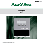
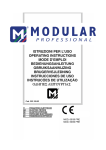
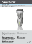
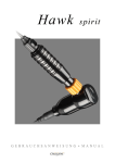
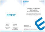
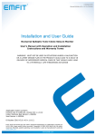
MT.DERM GmbH
WWW.CHEYENNE-TATTOO.COM
1
TATTOOGERÄTE
Aufbau der Cheyenne Power Unit
Power Unit I
Construction of the Cheyenne Power Unit
Power Unit II
Abb. 2 - Aufbauzeichnung Cheyenne PU II
Illustration 2 – Construction design of the Cheyenne PU II
(1) – Hubfrequenzanzeige
(2) – Taste „schneller“
(3) – Handstück ein/aus
(4) – Taste „langsamer“
(5) – Gerät ein/aus
(6) – Handstück I
(7) – Handstück II
(1) – display of frequency
(2) – „speed up“ button
(3) – hand piece on/off
(4) – „speed down“ button
(5) – Device on/off
(6) – hand piece I
(7) – hand piece II
2
MT.DERM GmbH
Aufbau der Cheyenne Power Unit
Power Unit I
Construction of the Cheyenne Power Unit
Power Unit II
Abb. 1 - Aufbauzeichnung Cheyenne PU II
Illustration 1 – Construction design of the Cheyenne PU II
(7) – „ON/OFF“-Schalter
(8) – Anschlussbuchse für Fußschalter
(9) – Anschlussbuchsen für Netzteil
(10) – Anschlussbuchse Handstück II
(11) – Anschlussbuchse Handstück I
(7) – “ON/OFF” switch
(8) – Connecting socket for the foot-operated switch
(9) – Connecting sockets for power supply unit
(10) – Connecting socket handpiece II
(11) – Connecting socket handpiece I
WWW.CHEYENNE-TATTOO.COM
3
TATTOOGERÄTE
Inhalt
INHALT......................................................................................................................... 4
1
ALLGEMEINE HINWEISE ................................................................................ 6
1.1
1.2
1.3
GEBRAUCHSANWEISUNG ......................................................................................................................................... 6
GRUNDLAGEN .......................................................................................................................................................... 6
TECHNISCHER FORTSCHRITT ................................................................................................................................... 6
2
ANWENDUNGSBEREICHE ............................................................................... 6
3
WICHTIGE HYGIENE- UND SICHERHEITSHINWEISE ........................... 6
4
INBETRIEBNAHME ............................................................................................ 7
4.1
4.2
4.3
GERÄTEAUFSTELLUNG ............................................................................................................................................ 7
GERÄTEANSCHLUSS ................................................................................................................................................. 7
BEDIENUNG ............................................................................................................................................................. 7
5
WARTUNG, STERILISATION .......................................................................... 8
6
FUNKTIONSAUSFALL, REPARATUREN, REKLAMATION ..................... 8
7
LIEFERUMFANG ................................................................................................ 9
8
GARANTIEERKLÄRUNG .................................................................................. 9
9
TECHNISCHE PARAMETER ............................................................................ 9
10 TRANSPORT- UND LAGERBEDINGUNGEN .............................................. 10
11 ADRESSEN .......................................................................................................... 10
12 ZUBEHÖR ........................................................................................................... 11
Version 1.35, 08/2013
4
MT.DERM GmbH
Table of Content
1
GENERAL REMARKS ...................................................................................... 12
1.1
1.2
1.3
MANUAL................................................................................................................................................................ 12
BASICS................................................................................................................................................................... 12
TECHNOLOGICAL ADVANCES ................................................................................................................................. 12
2
AREAS OF APPLICATION .............................................................................. 12
3
IMPORTANT HYGIENE AND SAFETY INSTRUCTIONS ........................ 13
4
OPERATION ....................................................................................................... 13
4.1
4.2
4.3
DEVICE SET-UP ...................................................................................................................................................... 13
DEVICE CONNECTION ............................................................................................................................................. 13
OPERATION ............................................................................................................................................................ 14
5
MAINTENANCE, STERILISATION ............................................................... 14
6
FAILURE MALFUNCTION, REPAIRS, CUSTOMER COMPLAINTS .... 15
7
SCOPE OF DELIVERY ..................................................................................... 15
8
WARRANTY DECLARATION ........................................................................ 15
9
TECHNICAL PARAMETERS .......................................................................... 16
10 TRANSPORT AND STORAGE CONDITIONS ............................................. 16
11 ADDRESSES ........................................................................................................ 17
12 AUXILIARY EQUIPMENT .............................................................................. 17
NOTIZEN /NOTES .................................................................................................... 18
NOTIZEN /NOTES .................................................................................................... 19
Version 1.35, 08/2013
WWW.CHEYENNE-TATTOO.COM
5
TATTOOGERÄTE
Herzlichen Glückwunsch zum Kauf Ihrer neuen Cheyenne Power Unit!
Die PUs sind digitale Steuergeräte für Tattoo-Maschinen. Sie wurden speziell für die Verwendung
mit der Cheyenne Hawk optimiert.
Für eine einwandfreie Handhabung lesen Sie die Gebrauchsanweisung bitte vor der ersten Inbetriebnahme sorgfältig durch. So werden Sie u. a. ein besseres Verständnis der technischen Funktionen
und Einsatzmöglichkeiten erlangen.
1
Allgemeine Hinweise
1.1 Gebrauchsanweisung
Diese Gebrauchsanweisung weist auf die bestimmungsgemäße Anwendung des Tattoo-Gerätes hin
und dient zur Verhütung von Gefahren. Sie muss von allen Personen gelesen und beachtet werden,
die dieses Gerät einsetzen bzw. anwenden, pflegen oder warten.
Diese Gebrauchsanweisung ist Bestandteil des Gerätes und muss dem Anwender ständig zur Verfügung stehen. Bei Weitergabe des Gerätes an Dritte ist sie mit dem Gerät zu übergeben.
1.2 Grundlagen
Die Gebrauchsanweisung muss vor der Inbetriebnahme komplett gelesen werden! Für eine von dieser Gebrauchsanweisung abweichende Inbetriebnahme oder Verwendung des Gerätes und deren Folgen übernimmt der Hersteller keine Haftung!
1.3 Technischer Fortschritt
Der Hersteller behält sich Änderungen im Sinne des technischen Fortschrittes vor.
2
Anwendungsbereiche
Die Cheyenne PUs werden als Steuergerät für Tätowier-Geräte zur Körpertätowierung von Menschen verwendet. Bitte beachten Sie die Gebrauchsanweisung der angeschlossenen Handstücke.
3
Wichtige Hygiene- und Sicherheitshinweise
Das Steuergerät muss mit einem weichen Tuch, welches mit einer milden Seifenlösung befeuchtet
wurde, abgewischt werden. Gegebenenfalls ein mildes Desinfektionsmittel, z.B. 70%-ige wässrige 2Propanollösung verwenden. Das Handstück sowie die Handstückablage müssen unmittelbar vor Gebrauch bzw. vor der Behandlung durch Abwischen mit einem Desinfektions- und Reinigungsmittel
getränkten weichen Tuch gereinigt werden. Das Steuergerät und das Handstück dürfen niemals selbst
6
MT.DERM GmbH
in Desinfektionsmittel getränkt werden, da sonst die Teile im Inneren korrodieren können. Vor der
Anwendung muss das Steuergerät, das Handstück, das Handstückkabel sowie die Handstückablage
mit einer Schutzfolie bzw. einem Schutzschlauch versehen werden.
Das Tätowieren muss in einem sauberen Raum stattfinden, wobei auf ein striktes Rauchverbot geachtet werden muss. Bitte beachten Sie hierfür die lokalen Bestimmungen zur Arbeitsplatzgestaltung.
4
Inbetriebnahme
4.1 Geräteaufstellung
Die Steuergeräte PU I und PU II sind für die Verwendung in Innenräumen bestimmt. Sie können
ohne Beeinträchtigung bei einer Raumtemperatur von 10°C bis 35°C betrieben werden. Vor Inbetriebnahme des Gerätes muss darauf geachtet werden, dass das Gerät sich an die Raumtemperatur
angepasst hat, da sonst das entstehende Kondensat die Elektronik beschädigt (bei 10°C Temperaturunterschied mindestens drei Stunden warten).
Das Gerät ist als Tischgerät konzipiert, d.h. es ist auf einer sauberen, festen und ebenen Unterlage
aufzustellen.
4.2 Geräteanschluss
Zunächst wird der Fußschalter mit der Buchse (8) auf der Rückseite des Gerätes verbunden. Danach
werden die Handstücke an die Buchsen (10) und (11) auf der Unterseite des Steuergerätes angeschlossen (bei der Power Unit I kann nur ein Handstück angeschlossen werden). Die Belegung der
Buchsen entspricht der Anordnung der Auswahlschalter für die Handstücke auf der Vorderseite des
Gerätes.
Zuletzt wird das Steckernetzteil an das Steuergerät angeschlossen. Das Gerät darf nur mit dem auf
dem Typenschild des Gerätes ausgewiesenen Steckernetzteilen betrieben werden. Die Netzspannung
muss mit der auf dem Aufdruck des Steckernetzteiles ausgewiesenen Geräte-Nennspannung übereinstimmen!
Die dafür vorgesehene Buchse (9) befindet sich ebenfalls auf der Rückseite des Steuergerätes. Nachdem das Steckernetzteil mit der Netzspannung verbunden wurde, leuchtet die rote „Power“-LED.
4.3 Bedienung
Der „ON/OFF“-Schalter (5) befindet sich an der rechten Seite des Steuergerätes PU II. Bei der PU I
gibt es einen Ein- und einen Ausschalter auf der Vorderseite des Gerätes (5).
Das Gerät wird durch die Betätigung des „ON/OFF“-Schalters eingeschaltet und auf dem Display
erscheint die voreingestellte Geschwindigkeit von 100Hz (100 Hübe pro Sekunde).
Durch Drücken der „Drive“-Taste (PU I) bzw. On/Off-Taste (PU II) wird das an Klinkenbuchse (10
bzw. 11) angeschlossene Handstück in Betrieb genommen. Nun leuchtet die gelbe LED neben dem
Tastenfeld ebenfalls und signalisiert damit den Betrieb des Handstückes.
WWW.CHEYENNE-TATTOO.COM
7
TATTOOGERÄTE
Die Stichfrequenz lässt sich im eingeschalteten Zustand in 10 Stufen von 60 bis 160 über die „▲“Taste (schneller) und die „▼“-Taste (langsamer) einstellen. Die gewählte Frequenz wird im Display
angezeigt. Mit nochmaliger Betätigung der „Drive“-Taste (PU I) bzw. On/Off (PU II) wird das
Handstück wieder ausgeschaltet. Beim Anschluss von zwei Handstücken an das Steuergerät PU II
kann durch Drücken der „I“-Taste und der „II“-Taste zwischen den Handstücken gewechselt werden.
Es ist auch möglich, das Gerät über den mitgelieferten Fußschalter zu bedienen. Durch eine Betätigung wird das angeschlossene und ausgewählte Handstück an- und bei nochmaliger Betätigung wieder ausgeschaltet.
Ein gefahrloser Betrieb ist nicht garantiert:
• wenn das Gerät bzw. das Zubehör sichtbare Beschädigungen aufweist
• wenn das Gerät nicht ordnungsgemäß arbeitet
• nach längerer Lagerung außerhalb des vorgeschriebenen Temperaturbereichs
• bei Transportschäden nach unsachgemäßem Transport
In diesen Fällen sollte das Gerät grundsätzlich dem autorisierten Fachhändler zur Überprüfung übergeben werden.
5
Wartung, Sterilisation
Vor Beginn sämtlicher Reinigungs- und Pflegearbeiten ist das Steuergerät vom Netz zu trennen! Das
Gerät ist nach jedem Gebrauch zu reinigen. Dabei soll nach folgendem Schema vorgegangen werden:
1. Das Steckernetzteil vom Netz trennen.
2. Das Steuergerät von allen Anschlusskabeln trennen.
3. Das Steuergerät mit einem weichen, feuchten Tuch abwischen. Es ist ein Desinfektionsmittel (70%-ige wässrige 2-Propanollösung) zu verwenden.
Achtung! Benutzen Sie keine Lösungsmittel zur Reinigung!
6
Funktionsausfall, Reparaturen, Reklamation
Bei Funktionsstörungen des Steuergerätes sollten Sie zunächst alle Komponenten wie das Netzteil
und das Handstück vom Gerät trennen. Nachdem Sie alle Anschlüsse überprüft und neu angeschlossen haben, sollte das Gerät wieder funktionieren.
Sollte sich die Funktionsstörung nicht beseitigen lassen, ist das Gerät einem autorisierten Fachhändler vorzustellen.
Reklamationen sind beim Fachhändler geltend zu machen.
Zur Entsorgung muss das Gerät an den Hersteller zurück
geschickt werden. Kontaktieren Sie hierzu Ihren Vertriebspartner.
8
MT.DERM GmbH
7
Lieferumfang
Art.Nr.
B-4.5 / B-4.4
E-1150 / E-1152
E-1000
7E-B4.4
Artikel
Cheyenne PU I / PUII Steuergerät
Netzteil WR9QG400 / GTM41060
Fußschalter
Gebrauchsanweisung
Lieferumfang
1
1
1
1
Wenn Sie weitere Informationen zu unseren aktuellen Angeboten und der Auswahl der Nadelköpfe
benötigen, nehmen Sie bitte Kontakt mit uns unter www.cheyenne-tattoo.com auf.
8
Garantieerklärung
Mit diesem Gerät haben Sie ein qualitativ hochwertiges Markenprodukt erworben. Die Zuverlässigkeit des Gerätes wird durch die neuesten Prüftechniken und die Zertifizierung gewährleistet.
MT.DERM GmbH ist zertifiziert nach:
•
•
DIN EN ISO 9001:2000 (Qualitätsmanagement -System zur Qualitätssicherung)
DIN EN ISO 13485:2003 (Qualitätsmanagement -System für Medizinprodukte)
Für das Gerät gilt die gesetzliche Gewährleistung von 2 Jahren auf Gerätestörungen, welche auf Materialfehler oder Verarbeitungsmängel zurückzuführen sind. Für Folgeschäden wird keine Haftung
übernommen. Für Schäden, die auf unsachgemäße Behandlung oder Nichtbeachtung der Gebrauchsanweisung zurückzuführen sind, werden grundsätzlich keine Gewährleistungen übernommen.
9
Technische Parameter
Steuergerättyp:
PU I / PU II
Nennspannung:
5-12V DC
Leistungsaufnahme:
15VA
Arbeitsfrequenz:
60-160 Stiche pro Sekunde
Antrieb:
Präzisionsmotor – DC 12V
Betriebsart:
Dauerbetrieb
WWW.CHEYENNE-TATTOO.COM
9
TATTOOGERÄTE
Betriebsbedingungen
Umgebungstemperatur: +10°C bis +35°C
relative Luftfeuchte:
30% bis 75%
Abmessungen:
110mm x 165mm x 55mm
(Breite x Höhe x Tiefe)
Gewicht:
ca. 260 g
Gerät entspricht den Anforderungen der Richtlinie
89/336/EWG (EMV Richtlinie )
Gebrauchsanweisung beachten!
10 Transport- und Lagerbedingungen
Umgebungstemperatur: -40°C bis +40°C
relative Luftfeuchte:
30% bis 75%
Luftdruck:
500 hPa bis 1060hPa
Vor Inbetriebnahme des Gerätes muss eine Sichtkontrolle durchgeführt werden, um Transportschäden sofort festzustellen. Wenn anzunehmen ist, dass das Gerät nicht mehr gefahrlos betrieben werden kann, ist es außer Betrieb zu nehmen und gegen unbeabsichtigtes oder unbefugtes Benutzen zu
sichern.
11 Adressen
Hersteller:
MT.DERM GmbH
Gustav-Krone-Str.3
14167 Berlin
Germany
10
MT.DERM GmbH
12 Zubehör
Die Cheyenne PU I und PU II wurde speziell für die Verwendung mit dem Tattoo-Maschine Hawk
von Cheyenne entwickelt.
Hawk
WWW.CHEYENNE-TATTOO.COM
11
TATTOOGERÄTE
Congratulations on purchasing your new Cheyenne Power Unit!
The PUs are digital control units for tattoo machines. They were especially optimised for use with
the Cheyenne Hawk.
For flawless handling and application please read the manual carefully before first using the machine. Amongst other things, you will be able to better understand the technical functions and usage
scenarios of the Hawk.
1
General remarks
1.1 Manual
This manual points out what the intended application of the tattoo device is and serves to prevent
accidents and annul dangers. This manual must be read and observed by all individuals that use, apply, maintain, service or clean this device.
This manual is a part of the device as a whole and must be made available at all times to the person
using or applying it. If the device is passed on to third parties, then the manual must be included in
this transaction.
1.2 Basics
The manual must be read from front to back before starting with any operative use of the machine!
The manufacturer does not assume any responsibilities or liabilities if this device is not used or operated for the explicitly stated purposes and the effects caused by this misuse/non-proper use!
1.3 Technological advances
The manufacturer would like to point out that the Cheyenne Hawk is subject to alterations and modifications without prior notice at any time.
2
Areas of application
The Cheyenne PUs are used as a control unit for tattoo devices that tattoo human bodies. Please read
and adhere to the manuals of the connected handpieces.
12
MT.DERM GmbH
3
Important hygiene and safety instructions
The control unit must be wiped with a soft cloth that has been moistened with a mild soap solution. If
necessary use a mild disinfectant, for example 70% water-2-propanol solution.
The handpiece as well as the handpiece storage equipment must be cleaned immediately before use
or before the treatment by wiping over said objects with a soft cloth that has been soaked with disinfectant and cleaning agent. The handpiece and the control unit are not allowed to ever be soaked in
disinfectants as otherwise internal parts might start corroding. Before use the control unit, the handpiece, the handpiece cable as well as the handpiece storage equipment must be covered with a protective cloth or sheet or with a protective sleeve or tube.
The tattooing must take place in a clean room where smoking is forbidden. With regard to this,
please observe the local regulations on the layout and organisation of workplaces.
4
Operation
4.1 Device set-up
The control units PU I and PU II are to be used indoors. They can be operated without any problems
in room temperatures ranging from 10°C to 35°C. Before the start of operation it should be ensured
that the device has adjusted to the room temperature as otherwise the condensate that is created could
damage the electronics (when there is a temperature difference of 10°C or more then please wait at
least three hours).
The device is designed as a tabletop unit; that means it is to be set up on a clean, stable and level
base or support.
4.2 Device connection
First the foot-operated switch is connected to the socket (8) at the back of the device. After this, the
handpiece is connected to the sockets (10) and (11) (with the PU I only one handpiece can be conected) on the underside of the control unit. The configuration of the sockets is in accordance with the
selection switch for the handpieces at the front side of the device.
The final step is to connect the power supply unit plug to the control unit. The device is only allowed
to be operated with the power supplies unit plug that is displayed on the type plate of the device. The
power supply voltage must be the same as the stated nominal voltage of the device which is on the
label of the power supply unit plug!
The socket (9) designed for this can also be found on the rear side of the control unit. After the power supply unit plug has been connected to the power supply voltage, the red “Power” LED goes on.
WWW.CHEYENNE-TATTOO.COM
13
TATTOOGERÄTE
4.3 Operation
The “ON/OFF” switch (5) can be found on the right side of the control unit PU II. The ON/OFF
switch of the PU I is located on the front side of the device (5).
The device is switched on by pressing the “ON/OFF” switch and on the display one can now see the
preset speed of 100Hz (100 strokes per second).
By pressing the “drive” switch (PU I) or the ON/OFF switch on the front side (PU II) the handpiece
that is connected to the jack plug socket (10 or 11) is turned on. Now the yellow LED beside the
switch field also lights up and thereby signals that the handpiece is also now operational.
The puncture rate can be set when on in 10 different steps, from 60 to 160Hz, using the “▲” button
(faster) and the “▼” button (slower).
The chosen rate is shown in the display. If one presses the “Drive” switch (PU I) or ON/OFF switch
(PU II) again, the handpiece is switched off once again. If one is connecting two handpieces to the
control unit PU II, then one can choose between the handpieces by either pressing the “I” button or
the “II” button.
It is also possible to operate the device with the aid of the foot-operated switch that is supplied. By
pressing it the handpiece that is connected and selected is switched on and if one presses again it is
switched off.
Safe operation is not guaranteed if:
•
•
•
•
the device or the auxiliary equipment is clearly and markedly damaged
the device does not work as it should
it has been stored for a longer period of time not within the specified temperature range
it has been damaged due to improper transport.
In these cases the device should be given to an authorised dealer so that it can be properly checked.
5
Maintenance, sterilisation
Before starting with any cleaning or maintenance work, the control unit is to be unplugged from the
power supply source! The machine has to be cleaned after every usage. Thereby one should adhere
to the following steps:
1. Separate the power supply unit plug from the power supply.
2. Separate the control unit from all connecting cables.
3. The control unit must be wiped with a soft, moistened cloth. Use a disinfectant (70% water-2-propanol) solution.
Warning! Do not use any solvents for the cleaning!
14
MT.DERM GmbH
6
Failure malfunction, repairs, customer complaints
When device malfunctions occur you should first of all disconnect all components such as power
supply unit and the handpiece from the device. After you have checked all of the connections and
reconnected them, the device should work again.
If the malfunction of the device cannot be resolved, then the device should be given to an authorised
dealer.
Customer complaints are to be made to the dealer.
For the disposal the device must be sent back to the manufacturer. Please contact your
distributor on this matter.
7
Scope of delivery
Art. No.
B-4.5 / B-4.4
E-1150 / E-1152
E-1000
7E-B4.4
Article
Cheyenne PU I / PU II Control Unit
Power Supply Unit WR9QG400 / GTM41060
Foot-operated Switch
Manual
Scope of delivery
1
1
1
1
If you need any further information on our current offers and the selection of needle heads available,
then please do contact us at www.cheyenne-tattoo.com.
8
Warranty declaration
With this device you have bought a high quality brand product. The reliability of the device is guaranteed by the newest test techniques as well as certification. MT.DERM GmbH has been certified in accordance with:
•
•
DIN EN ISO 9001:2000 (Quality management system for quality assurance)
DIN EN ISO 13485:2003 (Quality management system for medical products)
The legal warranty for this device is 2 years for malfunctions that have to do with faulty material or
manufacturing defects. No liability is assumed for any subsequent damage. For damage that is due to
improper handling or not following the manual instructions no warranty is assumed.
WWW.CHEYENNE-TATTOO.COM
15
TATTOOGERÄTE
9
Technical parameters
Control unit type:
PU I / PU II
Nominal voltage:
5-12V DC
Input power consumption:
15VA
Operational rate:
60-160 punctures per second
Drive:
Precision motor – DC 12V
Operational mode:
Continuous, long-term operation
Operational requirements
Ambient temperature:
+10°C to +35°C
Relative humidity:
30% to 75%
Measurements:
(width x height x
depth)
110mm x 165mm x 55mm
Weight:
ca. 260 g
Device complies with the requirements of the Directive 89/336/EEC (EMC Directive)
Please adhere to the manual!
10 Transport and storage conditions
Ambient temperature:
-40°C to +40°C
Relative humidity:
30% to 75%
Air pressure:
500 hPa to 1060hPa
Before the start of operation with the device a visual inspection has to be undertaken in order to ascertain if any transport damage has occurred. If one can assume that the device cannot be operated
safely anymore then it must be put out of commission and safeguarded against accidental or unauthorised use.
16
MT.DERM GmbH
11 Addresses
Manufacturer:
MT.DERM GmbH
Gustav-Krone-Str.3
14167 Berlin
Germany
12 Auxiliary equipment
The Cheyenne PU I and PU II was especially developed for use with the tattoo machine Hawk, also
manufactured by Cheyenne.
Hawk
WWW.CHEYENNE-TATTOO.COM
17
TATTOOGERÄTE
Notizen /notes
18
MT.DERM GmbH
Notizen /notes
WWW.CHEYENNE-TATTOO.COM
19
TATTOOGERÄTE
20