1
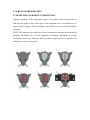
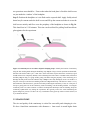
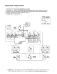
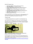
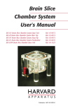
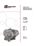
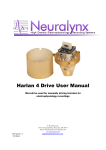
AUTOPATCHING: BEST EXPERIMENTAL PRACTICES (ver:09/03/2013) Synthetic Neurobiology Laboratory @ MIT Precision Biosystems Laboratory @ Georgia Tech TABLE OF CONTENTS 1. OVERVIEW: GOOD EXPERIMENTAL PRACTICES ............................................... 2 2. OVERVIEW: ANESTHESIA ........................................................................................ 2 3. SURGICAL PREPARATION ........................................................................................ 3 3.1 HEADFIXING AND BRAIN STABILIZATION ................................................................ 3 3.2 CRANIOTOMY.................................................................................................................... 5 3.3 DURATION OF EXPERIMENT ......................................................................................... 6 4. PATCH PIPETTES......................................................................................................... 6 4.1 PATCH PIPETTE FABRICATION AND STORAGE ........................................................ 6 4.2 INTRACELLULAR SOLUTION, PATCH PIPETTE FILLING AND INSTALLATION . 7 4.3 PREVENTING INTERNAL PIPETTE CLOGGING .......................................................... 7 4.4. MICROFIL STORAGE ....................................................................................................... 8 5. HEPA FILTERING ........................................................................................................ 8 6. CHLORIDING OF Ag/AgCl ELECTRODES ............................................................... 8 7. PIPETTE HOLDER MAINTENANCE ......................................................................... 9 8. ELECTRODE GROUND WIRE PLACEMENT ........................................................... 9 9. PRESSURE AND TUBING ......................................................................................... 10 10. REFERENCES ........................................................................................................... 10 The performance of the Autopatcher relies as much on its internal hardware and algorithms as on the quality of preparation for the experiment. Successful automated patch clamping, as with success of any in vivo electrophysiology experiment, is contingent on pristine experimental preparation – environmental cleanliness, solution purity and accuracy, and surgery quality. The following sections detail an attempted comprehensive list of good experimental practices that are of great benefit for effective Autopatcher operation. Experimenters are urged to carefully read this operating manual carefully before starting autopatching experiments, and refer to it for day-to-day troubleshooting. Please send any questions or feedback to [email protected]. 1. OVERVIEW: GOOD EXPERIMENTAL PRACTICES It is critical to ensure proper cleanliness of the working area (since any dirt, dust, or contamination could clog pipettes or impair cell recording quality), and to ensure high quality patch pipettes, freshly pulled according to an optimized and robust protocol to be used for the experiments. *Always follow federal and institutional rules on animal experiments!!!* It is highly recommended that Autopatcher users acquaint themselves with the existing in vivo patch clamping literature and protocols (e.g., 1-5 ) to get a full understanding of the best practices that have enabled research groups in the past to get consistent results using the techniques, and adapting them for specific experimental protocols as desired. Detailed below are the standard minimum preparation protocols that should be followed by users for best results. 2. OVERVIEW: ANESTHESIA The autopatcher algorithm was derived for whole cell patch clamping of cortical neurons in anesthetized mice (e.g. C57BL6, 6-12 weeks old), although it generalizes to other cell types in other brain regions and operates reasonably well in the awake state. All surgical procedures before the experiment (in case of an acute anesthetized prep) as well as during the recording experiment should proceed under full anesthesia for best results (e.g., 1-2% isoflurane in oxygen, or Ketamine, 100 mg/kg, intraperitoneally (IP) + Xylazine, 10 mg/kg, IP), although of course for scientific reasons one may prefer to work in the awake state (although yields and holding times will be lower than in the anesthetized state). If anesthetized autopatching is to be performed, the animal should be fully non-responsive to foot withdrawal reflex test throughout the experiment. Improper anesthesia can create motion artifacts, e.g. from unusually deep or fast breathing, that makes detecting contact with the neuron, and getting gigaseals, very difficult and will result in poor overall performance. 3. SURGICAL PREPARATION 3.1 HEADFIXING AND BRAIN STABILIZATION Optimal performance of the autopatcher requires a very stable head fixed preparation to hold the skull rigidly in place with respect to the autopatcher device. Detailed below are surgical steps for fixing a Delrin head plate to the skull in an acute anesthetized surgical procedure. NOTE: The instructions provided here are the recommended minimum requirements for headplate stabilization for an acute anesthetized experiment. Depending on specific institutional animal care mandates, other procedures might need to be performed in addition to the steps detailed below. Figure 1: Headfixing stabilization of the mouse brain for Autopatching Step 1: Anesthetize the animal using protocol approved by the institutional animal care committee. Step 2: Shave the hair on top of the brain using the hair trimmer. Clean excess hair and sterilize the scalp (e.g., using repeated and alternate cleaning with q-tips soaked in betadine and 70% ethanol (~3 times)). Step 3: Using a surgical blade or scissors, make a longitudinal incision in the scalp along the midline as shown in 3. Step 4: Open up the shaved scalp further using the surgical scissors to cut away excess scalp. (Note: Open up only as much scalp as required by the procedure.) Identify the craniotomy location and gently mark the spot (i.e., a small indentation) using a dental drill (e.g., as denoted by the big red dot in panel 4). Step 5: Using a dental drill, drill three anchor holes (~200 m diameter, using a dental drill) into the skull. Screw in the self tapping skull screws (e.g., Small Parts 000-3/32”) into the drilled holes, indicated by the three small red dots in 5. The skull screws are located just inside the rectangular window of the headplate. Step 6: Position the headplate so it sits flush on the exposed skull. Apply freshly mixed dental acrylic cement (e.g., Stoelting, Part# 51458) under the skull screws and fill up the cement such that it covers the skull screws entirely and flows over the periphery of the headplate as shown in 6. To further enhance stability it is also possible to cover the entire skull surface with a thin layer of transparent dental acrylic, after carefully marking the future craniotomy site. ALTERNATE: Metabond (Parkell, #S380) or a similar dental cement can be used instead of dental acrylic for this step. Step 1: Anesthetize the animal using approved anesthesia protocol. The breathing patterns of the animal under different anesthesia protocols differ greatly. The algorithm for the Autopatcher was developed and optimized on mice anesthetized with a cocktail of Ketamine and Xylazine. Use hair trimmers and spring scissors to trim hair on top of the head to prepare scalp for incision. Scrub the head with q-tip soaked in betadine, followed by a scrubbing with 70% ethanol to sterilize (repeat ~3X as required). Ensure all excess hair is removed from the surgical area during this procedure. Step 2: Using a #11 surgical blade, make a clean longitudinal incision (anterior to posterior) as shown in Fig 1.3. Step 3: Use small retractors to pull apart skin over the skull. Use a micro curette (Fine Science tools, 10080-05) to remove fascia, push back muscle. Identify the location for the craniotomy using the stereotax coordinates relative to bregma. Using a dental drill, gently make a drill marking at the spot. Step 4: Using a dental drill, drill three anchor holes (200 m diameter) into the skull. Screw in the self-tapping skull screws into the drilled holes, indicated by the three red dots in Fig. 1.5. The location of the skull screws should be made so that the desired recording craniotomy is roughly midway between the inner edges of the headplate window. We typically use two posterior skull screws and the one anterior skull screw, at the headplate windows. The relative distance between the anterior skull screw and the two posteriors ones should be ~7mm so that when the head plate is fixed the skull screws are just inside the ‘window’ of the headplate. Step 5: Position the headplate so it sits flush on the exposed skull. Apply freshly mixed dental acrylic cement under the skull screws and fill up the cement such that it covers the skull screws entirely and flows over the periphery of the headplate as shown in Fig 1.6. This should set in 15-20 minutes. This time can be utilized for pulling fresh borosilicate glass pipettes for the experiment. Figure 2: Craniotomy for in vivo whole cell patch clamping. Step 1: Identify the location of craniotomy using the burr marking made during the headfixing step. Step 2: Using a 250-450 m diameter dental drill, thin down the skull to make a pit 1-2 mm wide. At the end of this step the skull in the craniotomy region should not have been completely drilled, as this will damage the brain surface. It should be thin, translucent and flaky. Step 3: using a 31 gauge needle, gently poke holes along the periphery of the craniotomy pit to dislodge the flaky skull tissue left behind in Step 2. Step 4: Once fully dislodged, use the 31G needle or a fine pair of forceps to take the last remaining skull tissue. Step 5: Durotomy: The dura in a mouse is a very thin membrane, and often times it gets taken off when performing the craniotomy. If not, use a fine pair of forceps to gently pull if off. If the craniotomy results in bleeding, wait till bleeding subsides. Covering the craniotomy with 0.9% saline solution or artificial cerebrospinal fluid helps stem the bleeding. Keep the craniotomy hydrated this way during the experiment. We typically remove the ACSF bath during the pipette changeover process as it allows for easy visualization of the pipette tip relative to brain surface, but try to minimize the time. 3.2 CRANIOTOMY The size and quality of the craniotomy is critical for successful patch clamping in vivo. We have found that craniotomies with diameters > 1mm result in much higher brain movement than smaller craniotomies. Also ensure that the brain surface is not damaged when making the craniotomy. Always keep the brain surface moist and covered with ACSF or saline. 3.3 DURATION OF EXPERIMENT The time after the craniotomy is made has a significant effect on the success rate of patching (see Kodandaramaiah et al, Nature Methods 20121). Typically, best results are obtained within 3-4 hours from the time of first anesthesia induction. Multiple causes could contribute to this. It is possible that the brain tissue gets increasingly displaced as more and more pipettes are inserted. A further contributing factor is brain movement. As the animals go deep into anesthesia for long periods of time, breathing becomes deeper, less frequent and results in larger brain movements that are detrimental to patching. Another factor is natural brain swelling, and that adds to the exaggerated brain movement as well. 4. PATCH PIPETTES 4.1 PATCH PIPETTE FABRICATION AND STORAGE For characterizing the performance of the autopatcher, we used a P-97 pipette puller (Sutter Instruments) for making patch-clamp grade pipettes. We programmed the P-97 puller for pulling patch pipettes using capillary glass of 0.69 mm ID, and 1.2 mm OD (Warner Instruments Order# 64-0790). The filament ramp test values of most pipette pullers can however drift depending on usage and time. Consult the relevant user manual for more information on running the ramp test and detailed instructions for programming the pipette puller for pulling patch clamp grade pipettes. An excellent resource for learning how to pull pipettes is Sutter Instruments’ Pipette Cookbook. In our experiments, we used pipettes in the range of 6-9 M, and the autopatcher is programmed to allow pipettes in the resistance range of 3-9 M. If a stable pipette pulling program is used in the pipette puller, it is possible to make pipettes with resistances that do not vary significantly (+1 M variation) in a day’s experiment. At least until the pipette-pulling program has proved itself to be extremely reliable, it is highly recommended that the user visually inspect at least one of each pair of pipettes in a microscope at 40x magnification. Moreover, gloves should be worn at all times, to prevent the risk of contamination. If you are new to in vivo autopatching, a good starting point is to use patch pipettes that you know already work with cultured neurons, or slices. The quality and freshness of pipettes used are critical parameters that affect the performance of the Autopatcher. For experiments, avoid using pipettes that are older than a few hours for patching with the Autopatcher. Once pulled, ensure the pipettes are stored in the closed, dust-free storage container. 4.2 INTRACELLULAR SOLUTION, PATCH PIPETTE FILLING AND INSTALLATION The intracellular solution used to fill the patch pipettes is an extremely important element in a successful autopatch experiment. Ideally, solution batches that have already been shown to work well in slice or in vivo should be used, at least initially. In any case, it is highly recommended to use well-validated recipes from established electrophysiology laboratories. The solution we use in our laboratory consists of: 125 potassium gluconate (with more added empirically at the end, to bring osmolarity up to ~290 mOsm), 0.1 CaCl2, 0.6 MgCl2, 1 EGTA, 10 HEPES, 4 MgATP, 0.4 Na GTP, 8 NaCl (pH 7.23, osmolarity 289 mOsm). Pipettes can be back-filled using the Microfil ® loading needles (World Precision Instruments). Always wear clean gloves when handling pipettes. It is recommended that the user change gloves frequently during an experiment involving multiple autopatching trials. Keep the intracellular solution on ice during the experiment. Ensure that the fragile pipette tips are never inadvertently broken by contact with any objects. 4.3 PREVENTING INTERNAL PIPETTE CLOGGING IMPORTANT: READ CAREFULLY One of most common reason for failure of the autopatcher is the internal clogging of the pipettes. Internal clogging of pipettes due to particulate matter settling down at the tip of the pipette causes both transient fluctuations in the pipette resistance during autopatching as well as irreversible increases in pipette resistance. Both these factors result in false positives when the autopatcher is detecting neurons. This is because the pipette resistance is the sole parameter based on which the autopatcher carries out all tasks and decisions. The user can take several steps to minimize these effects, as detailed below. 4.4. MICROFIL STORAGE Ensure that the Microfils are stored in filtered 70% ethanol solution when not in use. Leaving the Microfil outside overnight may result in the accumulation of particulates at the tip of the Microfil that may end up clogging the pipettes internally due the high pressure they are held at during the initial descent to depth during autopatching. 5. HEPA FILTERING It is recommended that the laboratory space in which the autopatcher is setup is equipped with a HEPA filter. HEPA filtering the air in our laboratory space has resulted in significant reduction in pipette clogging in our own laboratory. 6. CHLORIDING OF Ag/AgCl ELECTRODES The pipette holder attached to the headstages has a silver wire connecting the gold pin to the pipette solution in the pipette. For proper electrical connectivity, the silver wire is “chlorided” (coated in silver chloride) by immersing the wire in bleach for 5-10 minutes. It is important to properly chloride the pipettes to prevent current drifts when autopatching. However too much chloriding (>15 minutes) is also bad, as Ag/AgCl flakes can get disloged from the wire, settle down at the tip and cause transient or irreversible increases in pipette resistance, which interfere with proper functioning of the autopatcher. To prevent this, the chloriding should be done for a maximum of 10 minutes. After chloriding clean the wire thoroughly (e.g., 10 rinses for 1 minute each) in sterile saline. This step is important not only in preventing any trace of bleach from contaminating the electrode holder, but also in helping remove any loosely attached Ag/AgCl flake from the surface of the wire. The probability of tip clogging is highest when a new Ag/AgCl wire is installed. One good diagnostic measure that we use is to check the pipette resistance over a period of 12 minutes after installation to see if the pipette resistance drifts or fluctuates over this time. Typically, while in saline or ACSF, the pipette resistance should not vary more that 0.1 M. If it does, and the tip is not directly in contact with the surface of the brain, replace the pipette with a fresh one. 7. PIPETTE HOLDER MAINTENANCE It is possible that, over time, particulates and other debris can accumulate in the pipette holder (Molecular Devices, 1-HL-U), the o-ring bushing and other areas that can come in contact with the pipettes. It is recommended that the pipette holder also be periodically cleaned to prevent such accumulation. 8. ELECTRODE GROUND WIRE PLACEMENT The placement of the ground wire is crucial for ensuring stable current readout. We typically use an AgCl pellet connected to the ground wire. During operation, ensure that the ground wire Ag/AgCl pellet is in complete contact with the skull surface. This prevents drifts in baseline current values. If too much drift is noticed, coating the pellet in 1-3% Agar made up with sterile saline can help mitigate the problem. Improper contact between the skull and the ground electrode results in pipette current offsets that are modulated at heartbeat (1-3 Hz) and breathing frequency (0.5-0.25 Hz, depending on anesthesia), and will affect the resistance measurement of the pipette during autopatcher operation. Note that if light sources for optogenetics are being used, light hitting the ground wire or the wire in the patch pipette may yield an artifact due to to photelectric effect. 9. PRESSURE AND TUBING Appropriate pressure at each stage of the autopatching process is crucial to successful recordings. A number of failure modes could therefore sometimes be due to either inappropriate pressure settings in the software or to hardware failure. A common, and easily fixable, problem is leakage of pressure at one or more junctions in the pipette holder. It is therefore important to make sure, at the beginning of each session, that the tubing is properly connected to the pipette holder and, at the beginning of each trial, that the screw-on caps in the holder are properly tightened. If it is suspected that the pressure box is malfunctioning, it can be helpful to check the pressure in the line connected to the pipette holder with a manometer. 10. REFERENCES 1. 2. 3. 4. 5. Kodandaramaiah, S.B., Franzesi, G.T., Chow, B.Y., Boyden, E.S. & Forest, C.R. Automated whole-cell patch-clamp electrophysiology of neurons in vivo. Nat Meth 9, 585-587 (2012). Lee, A.K., Epsztein, J. & Brecht, M. Head-anchored whole-cell recordings in freely moving rats. Nat. Protocols 4, 385-392 (2009). Lee, A.K., Manns, I.D., Sakmann, B. & Brecht, M. Whole-cell recordings in freely moving rats. Neuron 51, 399-407 (2006). Margrie, T.W., Brecht, M. & Sakmann, B. In vivo, low-resistance, whole-cell recordings from neurons in the anaesthetized and awake mammalian brain. Pflugers Arch 444, 491-498 (2002). Margrie, T.W. et al. Targeted whole-cell recordings in the mammalian brain in vivo. Neuron 39, 911-918 (2003).