1
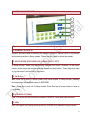
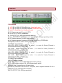
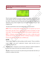
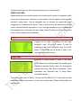
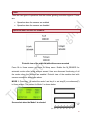
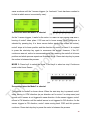
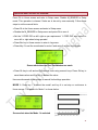
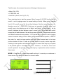
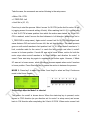
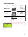
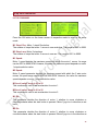
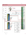
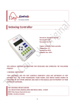
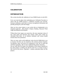
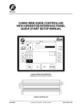
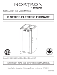
TNC-G10 Surface Grinder controller Document: Operation Manual Document #: T10 Document Rev: 1.0 Product: TNC-G10 Surface Grinder controller Product Rev: 1.0 Created: Jan, 2014 Updated: Jan, 2015 THIS MANUAL CONTAINS INFORMATION FOR INSTALLING AND OPERATING THE FOLLOWING PRODUCT: TNC-G10 SURFACE GRINDER CONTROLLER “TINY CONTROLS” AND THE TINY CONTROLS COMPANY’S LOGO ARE COPYRIGHTS OF TINY CONTROLS PVT. LTD. OTHER TRADEMARKS, TRADE NAMES, AND SERVICE MARKS OWNED OR REGISTERED BY ANY OTHER COMPANY AND USED IN THIS MANUAL ARE THE PROPERTY OF THEIR RESPECTIVE COMPANIES. TINY CONTROLS PRIVATE LIMITED C-55, NISHAT PARK, KAKROLA MOR, NEW DELHI, INDIA – 110078 WEB: http://www.tinycontrols.com PHONE: +91-991-119-3210 1 CONTENTS Item Page No. GENERAL DESCRIPTION SPECIFICATIONS/ FEATURES LOCATION OF COMPONENTS TERMINALS OPRATING THE SURFACE GRINDER CONTROLLER 1. HOME SCREEN 2. JOGGING 3. SETUP SCREEN 3 3 4 5 MODES 1. SENSORS ENABLED MODE 1 MODE 2 MODE 3 2. SENSORS DISABLED MODE 1 MODE 2 MODE 3 8 8 8 9 10 11 11 12 13 BRIEF VIEW OF OPERATION 14 HOMING 15 SET UP MENU COMMANDS 16 EMERGENCY 17 CONNECTION DIAGRAM 18 6 7 7 2 GENERAL DESCRIPTION Tiny Controls’ surface grinder controller (SGC) is a new concept designed especially for grinding operations. It is a versatile and economical solution designed to automate the repetitive grinding tasks. It features automated longitudinal and cross feed. This compact 2-axis surface grinding controller utilizes a simple and easy operating interface and three selectable mode to help automate repetitive grinding tasks, delivering the best results. The following commands are supported: (see Setup section for more details) Motion setup: M1Speed, M2Speed, M1Dir: CCW/ CW, M2Dir: CCW/ CW, M1Accel, M2 Accel, M1HSpeed, M2HSpeed Motion commands: M1Steps/ Rev, M2 Steps/ mm SPECIFICATION/FEATURES: Supply Voltage: 90V to 250V AC 50Hz/60Hz. Max Pulse Rate: 40 KHz. Overall Size: 165mm x 102mm x 76 mm. Mounting: Panel mounts: 155mmx92mm. Locomotion: Longitudinal (X) and Cross feed (Y). Control: Automatic mode select: 3 modes. Manual mode select: 3 modes. Jogging Longitudinal and cross feed speed control. Emergency stop. Speed control by potentiometer Inputs: 3 NPN Proxy (X limit, Y limit and Emergency input) + 1 On-Off switch for start- stop. Outputs: 2 for motor1 (STEP and DIR) +2 motor2 (STEP and DIR) +Two 12 V outputs (for NPN proximity type sensor) +5 V (for POT connections). Display: 20x4 LINES alphanumeric LCD. Operating interface: User friendly keys. Max Operating Temperature: 55 deg C. 3 LOCATION OF COMPONENTS: Major components of the Controller 5 4 3 2 1 The description of these components is as following: 1. NUMERIC KEYS (0-9) Numeric keys are used for entering the numeric values for manual limits in Jog screen and entering values in Setup screen. These are also used to select the modes. 2. NAVIGATION KEYS PANEL (UP, DOWN, RIGHT, LEFT) In Setup screen, these keys are used to navigate the cursor. However, in the home screen, these keys are used to alter the speed and feed value. These keys are used to jog the motor1 and motor2 in jog menu. 3. OK & Esc OK: Press OK to enter in Setup screen from Home screen. In Setup screen, pressing this key saves the modified values in EEPROM. Esc: Press Esc to exit out of Setup screen. Press Esc key in home screen to enter in jog screen. 4. LCD DISPLAY (20x4) This LCD shows all the information related to MODES, Home and other screens. 5. LEDs RED LED glows on homing and any activity. GREEN LED indicates long key press. 4 TERMINALS REMOVABLE BLOCK TERMINALS: PIN NUMBER 1. ~AC (90V to 250V AC 50Hz/60Hz Live, Handle with care). 2. ~AC (90V to 250V AC 50Hz/60Hz Neutral, Handle with care). 3. Earth (To Earth Main line, Handle with care). 4. 0V (Common ground, Connect to POT). 5. 5V OUTPUT (For POT connection). 6. 12V OUTPUT (For NPN type proximity sensors). 7. Emer- EMERGENCY INPUT (Connect output of N/O, NPN type proximity switch). 8. 0V (Common ground, For NPN type proximity). 9. 0V (Common ground, Connect to STEPPER DRIVER e.g. TSTEP-484). 10. Speed (Connect to center of POT for speed input). 11, 12. NC- not connected. 13. X-STP- STEP PULSE OUTPUT for motor 1, i.e. motor for X-axis (Connect to STEPPER DRIVER eq. TSTEP-484). 14. X-DIR - DIRECTION output for motor 1, i.e. motor for X-axis (Connect to STEPPER DRIVER eq. TSTEP-484). 15. Y-STP- STEP PULSE OUTPUT for motor 1, i.e. motor for Y-axis (Connect to STEPPER DRIVER eq. TSTEP-484). 16. Y-DIR - DIRECTION output for motor 1, i.e. motor for Y-axis (Connect to STEPPER DRIVER eq. TSTEP-484). 17, 18. NC- not connected. 19. 0 V (Common Ground). 20. X- LIM Connect output of NO, NPN type proximity switch). 21. Y- LIM (Connect output of NO, NPN type proximity switch). 22. Start- Stop: Connect the on- off switch here. 23. Com-In (Common for X-Lim and Y- Lim inputs, can be supplied external 12 volt or jumped from 12v output from the controller). 24. 12V OUTPUT (For NPN type proximity). 5 OPERATING SURFACE GRINDING CONTROLLER Home Screen: When the power is applied to the board, a splash screen appears, after that the Home screen appears. The user can change the modes by pressing the respective numeric key. Stop or Continuous can be set along with mode by pressing key4. Speed can be adjusted by using up-down navigation keys and feed can be adjusted using left- right navigation keys. The above specified three terms are described in the subsequent section. NOTE: There is a homing feature available on key 8. If user presses key 8 on the home screen, the motor moves to respective home position and searches for home sensor input. The home speed can be adjusted in Set up screen for respective mode. NOTE: If Emergency input is received anytime, the motion is halted and current operation (even program run mode) is aborted. A message of emergency is displayed. Press any key and the control will return to HOME screen. MODES: There are three modes that surface grinding controller supports. These are called as mode 1, mode 2 and mode 3 respectively. However, mode can also be set as continuous (C) or Stop (S). Continuous (C): If continuous is set, the motor continues to rotate and repeats the process after homing until the start key is pressed to stop the motors. Stop (S): If stop is set, the motors stop after homing and rotate when the start key is pressed to commence the motion. 6 Continuous and start can be set by pressing the key4 in Home screen. SPEED AND FEED: Speed determines the speed at which motor1 and motor2 rotates. Its maximum value can be set in Setup menu. However, in home screen, it can be altered in the range set entered in setup menu. Use up navigation key to increase the speed and down navigation key to decrease the speed. Feed controls how far the table moves on the Y-axis. Feed defines the increment in Y-axis. Use right navigation key to increase and left navigation key to decrease the feed value. Press Ok button to enter in the set up screen of the respective mode selected. Jogging Jogging can be done by pressing left and right navigation keys for motor1 (motor X) and by pressing up and down navigation keys for motor2 (motor Y). Press Esc key as shown to enter in the jog screen from Home screen. Setup screen Press Ok in Home screen to enter in the setup menu. Make all the settings about the enabling and disabling of sensors, motors’ steps, dir, acceleration settings and many other Setup commands. These commands are discussed late in Setup Menu commands section. The limit for the travel of Motor1 (X-axis) and the Motor2 (for Y-axis) can be fixed manually as well as by sensors. It is also set in Setup menu. Refer to Setup Menu for more details. 7 Modes There are two types of operations that the surface grinding controller supports. These are: Operation when the sensors are enabled Operation when the sensors are disabled Operation when sensors are enabled: Pictorial view of the machine bed with sensors mounted Press Ok in Home screen and enter in Setup menu. Enable the M_SENSOR for automatic motion after being sensors sensed. Here are discussed functioning of all the modes when the sensors are enabled. Pictorial view of the machine bed with sensors mounted is also shown above. MODE 1: Press key 1 to select the mode1 and key 4 to set stop(S) or continuous(C) in Home screen. The pattern for Mode 1 is shown below. Screen shot when the Mode1 is selected 8 Take the case; the commands are set as following in the setup menu: Motor1 Dir: CCW Motor2 Dir: CCW Press the start-stop switch/key. Motor1, motor for X-axis starts moving in CCW direction. It continues to move until the X-sensor (X-Right/ X-left as per the machine is set by user) is not triggered in CCW direction. As the X-sensor triggers, motor2, the feed motor or motor for Y-axis moves in CCW direction (direction set in Setup menu) the feed distance set in home screen and motor1 starts moving in CW (reverse) direction and continues its motion until the Xsensor is not found triggered in CW direction. As this sensor triggers, Motor2 moves in the CCW direction again and motor1 starts moving in CCW direction again and the process continues. When the Y-sensor (Y-up/ Y-down sensor) at Y-axis is triggered (i.e. feed axis/ Y-axis has been reached to its limit at which Y-sensor is mounted by user), it waits for motor1 to reach at its limit position and then homing of motor2 takes place. When motor2 reaches at its home position, if mode 1S was set in home screen, both the motors stop at home position and direction of motor1 is saved. Press start-stop key to commence the motion and repeat the process again. However, if Mode 1C was set, machine reaches to its home position configured by user, direction for motor1 is saved and all the above process again starts. Press the start-stop key to pause the motion in between the process. MODE 2: Press key2 to select the mode 2 and key4 to select as stop/ Continuous mode in the Home Screen. The pattern for Mode 2 is shown below. Press start-stop key. Motor1 starts moving in CCW direction (direction set for motor1 in Setup menu) and continues to move in same direction until the X-sensor is not triggered (X-Right/ X-left as per the machine is set by user). When the X-sensor triggers, motor1 starts moving in CW direction and moves until the X-sensor in CW triggers. As the X-sensor triggers, motor2 moves the feed distance set in Home screen in CCW direction (direction set for motor1 in Setup menu) and motor1 moves back in CCW direction again and whole process continues 9 same as above until the Y-sensor triggers (i.e. feed axis/ Y-axis has been reached to its limit at which sensor is mounted by user). Screen shot when the Mode2 is selected As the Y-sensor triggers, it waits for the motor1 to reach its limit position and after it, homing of motor2 takes place. If 2S was set in home screen (Stop/ Continuous is selected by pressing key 4 in home screen before starting the motion for motors), motor2 stops at its home position and the direction for motor1 is saved. It is required to press the start-stop key again to commence the motion. However, if the 2C; continuous was set, motion is commenced again after reaching the motor2 at its home position and whole process repeats as illustrated above. Press start-stop key to pause the motion in between the process. MODE 3: Press key3 to select the mode 3 and key4 to select as stop/ Continuous mode in the Home Screen. Screen shot when the Mode3 is selected The pattern for mode3 is shown above. When the start-stop key is pressed, motor1 starts moving in CCW direction (as per direction set for motor1 in setup menu) and moves until X-sensor is not triggered in same direction. As the sensor triggers, motor1 moves in CW direction until the switch/ sensor is not triggered in CW direction. As the sensor triggers in CW direction, motor1 starts moving back CCW and this process continues. Press start-stop key to pause the motor in between the process. 10 Operation when sensors are disabled: Press Ok in Home screen and enter in Setup menu. Disable M_SENSOR in Setup mode. This operation is chosen if limits are to be set by user manually. Follow these steps to set the manual limits: Press Ok in the Home screen and enter in Setup menu. Disable the M_SENSOR in Setup menu and press Ok to save it. Set the Y-FEED DIR as left/ right as per requirement. Y-FEED DIR sets motor2 to move left or right when being operated. Press Esc key in Home screen to enter in Jog menu. Press Key 0 to set the coordinates for motor1 and motor2 as zero coordinates. Screen shot when the Zero Coordinates are made Press Ok key to edit and set the desired limits using numeric keys. Press Ok key to save these values and Esc key to discard the value. Here are discussed all the modes in manual limit settings operation: MODE 1: Press key 1 to select the mode1 and key 4 to set stop or continuous in Home screen. The pattern for Mode 1 is shown below. Screen shot when the Mode 1 is selected 11 Take the case; the commands are set as following in the setup menu: Motor1 Dir: CCW Y-FEED DIR: Left Limit Set is (Lim-X, Lim-Y)=(10, 10) Press start-stop key to start the process. Motor1 moves X=10 CCW (as the limit for motor1 is set in jogging screen for manual setting of limits). When motor1 reaches Limit X=10, motor2 moves left, the set feed distance. Note that motor2 moves in the direction as set in Y_FEED DIR if limits are set manually. However, motor1 and motor2 jogs in the direction as set for Motor1 and Motor2 in Setup menu. As the motor2 completes the feed distance, motor1 moves X=10 CW and after this, motor2 moves the set feed distance in left and the process continues. This process continues until Motor2 reaches its limit position, Y=10 (as the limit for motor2 is set in jogging screen for manual setting of limits. When motor2 reaches the limit position, it waits for the motor1 to reach its home position and then motor2 moves back to its home position decided. If Mode 1S was set in home screen for mode, motion stops after reaching to home position and direction for motor1 is saved. Start-stop key is required to be pressed again to commence the motion. However, if 1C was set, motor1 and motor2 repeats all the process. Press start-stop key to pause the motion in between the process. MODE 2: Press key 2 to select the mode2 and key 4 to set stop or continuous in Home screen. The pattern for Mode 2 is shown in below: Screen shot when the Mode 1 is selected 12 Take the case; the commands are set as following in the setup menu: Motor1 Dir: CCW Y-FEED DIR: Left Limit Set is (10, 10) Press key to start the process. Motor1 moves X=10 CCW (as the limit for motor1 is set in jogging screen for manual setting of limits). After reaching limit X=10, it moves back to limit X=10 CW at same position from which the motion was started. As X-limit =10 CW is reached, motor2 moves the feed distance in Left direction (direction as set in Y_FEED DIR in setup menu). Again motor1 moves Limit X=10 CCW and moves back same distance CW and motor2 moves left, the set feed distance. The same process goes on until motor2 reaches to limit position Limit Y= 10. When motor2 reaches to Ylimit, controller waits for the motor1 to reach the limit position and after it, motor2 moves to its home position. If mode 2S was set in home screen, motion for both the motor stops when motor2 reaches to its home position and direction for motor1 is saved. Press start-stop key again to commence the motion again. However, if Mode 2C was set in home screen, whole the above process repeats when motor2 reaches to home position. Press Start-stop key to pause the motion in between the process. MODE 3: Press key3 to select the mode 3 and key4 to select as Stop/ Continuous mode in the Home Screen. Screen shot when the Mode3 is selected The pattern for mode3 is shown above. When the start-stop key is pressed, motor moves in CCW direction (as per direction set for motor1 in setup menu) and moves back in CW direction after completing the X-limit=10 CCW. When motor moves Limit 13 X=10 CW, motor moves back Limit X=10 CCW. This process continues. Press startstop key again to pause the motion. Brief view for operations: Operation when sensors are enabled: Modes Mode1: Feed at both sides Mode 2: Feed at one end only Mode 3: No feed Modes Patterns Operations 1. 2. 3. 4. Motor1 moves CCW. Motor2 moves CCW. Motor1 moves CW. Same as step 1. 1. 2. 3. 4. Motor1 moves CCW. Motor1 moves CW. Motor2 moves CCW. Same as step 1. 1. 2. 3. Motor1 moves CCW. Motor1 moves CW. Same as step 1. 14 Operation when sensors are disabled: Modes Mode1: Feed at both sides Mode 2: Feed at one end only Mode 3: No feed Modes Patterns Operations 1. 2. 3. 4. Motor1 moves CCW. Motor2 moves CCW. Motor1 moves CW. Same as step 1. 1. 2. 3. 4. Motor1 moves CCW. Motor1 moves CW. Motor2 moves CCW. Same as step 1. 1. 2. 3. Motor1 moves CCW. Motor1 moves CW. Same as step 1. Homing Homing feature is available on key 8. If the user presses key 8 in home screen, motors moves to respective home positions and searches for home sensor input. The home speed can be adjusted in Set up screen for respective mode. 15 Set up menu commands: LIST OF COMMANDS Press the OK button on the home screen of respective mode to enter in the setup mode. M1 Steps/ Rev: Motor 1 steps/ Revolution. The number of steps that motor 1 moves in one revolution. The range is 0001 to 9999. M2 Steps/ mm: Motor 2 steps/mm. The number of steps that motor 2 moves in one mm. The range is 0001 to 9999. M1 Speed: Motor 1 speed decides the maximum speed with which the motor 1 moves. Its range can be 0001 to 9999 RPM. However, the value for maximum speed depends on motor 1 steps/revolution value. M2 Speed: Motor 2 speed parameter decides the maximum speed with which the Y-axis motor moves. Its speed range can be 0001 to 9999 RPM. However, the value for maximum speed depends on motor 1 steps/revolution value. M1Accel (value) range is 01 to 20 This command is used to set acceleration for motor 1. M2Accel (value) range is 01 to 20 This command is used to set acceleration for motor 2. M1 Dir: This parameter decides the direction of motor 1, whether to move clockwise or counterclockwise when the start button is pressed. Motor1 jogs too in direction as set here. M2 Dir: This parameter decides the direction of motor 2, whether to move clockwise or counterclockwise when the start button is pressed. Motor2 jogs too in the direction as 16 set here. However, if M_SENSOR is disabled, then motor2 direction is set by Y_FEED DIR as discussed below. Speed_POT: This parameter enables or disables the use of pot. The user can change the speed by using Pot. However if pot is enabled, the user can’t set the speed by keys. M1HSpeed: This parameter decides maximum home speed in RPM. It is the maximum speed that the motor 1 achieves for home. Its range is 1 to 9999 RPM. However its value depends on the motor 1 steps/rev value. M2HSpeed: This parameter decides maximum home speed in RPM. It is the maximum speed of motor 2 that it achieves for home. Its range is 1 to 9999 RPM however its value depends on motor 2 steps/mm value. M_SENSOR: This parameter if enabled enables the sensors of limits and limits can’t be set manually. However, if disabled, disables the limit sensors and user set the limits manually in jog screen. Y_FEED DIR: This parameter sets the direction of motion for motor2 if M_SENSOR is enabled. Fr reset: This parameter resets all the parameters to factory defaults. Emergency When the emergency switch is triggered, the adjacent screen is displayed. Restart the system again to exit from emergency. 17 CONNECTION DIAGRAM 18