1
Installation Instructions for FRM220-FXO/FXS
FXO/FXS POTS Over Fiber Optic
Slide-in-Module Media Converter
Description
CTC Union’s FRM220-FXO/FXS POTS over fiber media converter connects central-office
voice grade signal to distant POTS (Plain Old Telephone Service) equipment using
standard telephone signaling. It can extend, over fiber, the distance between two voice
path communication devices by up to 120km using single mode fiber.
The FRM220-FXO/FXS provides audio transmission, caller ID, ringing at the distant end
and automatic ring down. Two units are required to implement an end to end system. The
RJ-11 connector provides the electrical interface between the media converter and the
telephone device or PSTN.
The FRM220-FXO/FXS is designed to be installed in FRM220-CH20 (20 slots Chassis) for
CO side or installed in FRM220-CH01(1 slot Chassis) for CPE stand-alone.
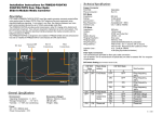
DC Jack
External DIP
Switches
RJ11C
Connections
Fiber
Connections
Technical Specifications
Copper Connector
FXO/FXS :
Phone Connector :
FXO Mode
Impedance :
Coding :
Loop Current :
Ring Frequency :
Insertion Loss :
FXS Mode
Impedance :
Coding :
Dial :
Battery Source :
Ringing Waveform :
Ringing Supply :
Ring Frequency :
Ring Cadence :
Selectable
RJ-11C
600 ohm
16 bits linear
10 ~ 100mA
Acceptable 20 ~ 55Hz
0.0r 1.0dB at 1000Hz
600 ohm
16 bits linear
DTMF and Pulse Dial
48VDC r 4V
Sine wave
60Vrmsr 10%
20/25/30/35/40/45/50/55 Hz selectable
FXS to FXS : On / 1 second, Off / 2 second
FXO to FXS : Reproduces the cadence of FXO
0.0r 1.0 dB at 1000Hz
4.0B (Ring Equivalence Number)
Insertion Loss :
REN:
Fiber Optic Connectors
Two connectors are provided for fiber optic cable connection.
One is labeled "TX" for transmission of optical data, the other is labeled "RX" for reception
of optical data.
DIP Switch Setting (for firmware version 3.03)
DIP SW State
-1
-2
OFF
ON
ON
General Specifications
Environment
•Operating Temperature : 0 - 50 ɗ
•Storage Temperature : -10 ~ 60 ɗ
•Humidity : 5 ~ 90% non condensing
Power
•DC +12V / 800mA input
•Power Consumption : 5 W
Dimension & Weight
•88mm x 137mm x 20.8mm (Line card)
(WxDxH)
•Weight : 450g
Main Mode
setting
OFF
FXS Mode
20~35Hz
ON
FXS Mode
40~55Hz
OFF
-3
OFF
ON
OFF
ON
OFF
ON
OFF
ON
DIP SW State
-4
OFF
OFF
ON
ON
OFF
OFF
ON
ON
OFF
OFF
ON
OFF
OFF
ON
ON
ON
FXO Mode
Sub-function
Ring frequency,
Ring frequency,
Ring frequency,
Ring frequency,
Ring frequency,
Ring frequency,
Ring frequency,
Ring frequency,
Ring frequency,
20/25Hz
Ring frequency,
30/35Hz
Ring frequency,
40/45Hz
Ring frequency,
50/55Hz
20Hz
25Hz
30Hz
35Hz
40Hz
45Hz
50Hz
55Hz
When installing with NMC in CH20, the NMC-R2 version must be 3.26 or above to manage these settings.
As with all FRM220 series products, once installed in the managed chassis, the DIP settings have no effect.
All setting is then performed via the Network Management Controller (NMC) of the chassis.
V.: 3.2
Installation
Connect the RJ-11 cable to the FRM220-FXO/FXS. The converter should be setup to
operate in FXO or FXS mode and the fiber link will be indicated on the LED. Follow the
connection examples below. Install the fiber converter with the DC power adapter provided
(+12VDC, 800mA) and connect the adapter to an AC outlet .
Connections
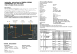
The following example illustrates the connection scheme when connecting PBX or PSTN
to telephone through the fiber converter.
FXO
Fiber Cable
FXS
PBX
Telephone
The following example illustrates the Automatic Ring-Down connection scheme (Hot Line)
when connecting telephone to telephone through the fiber converter.
FXS
Fiber Cable
Telephone
PWR
FXS
Telephone
TEST
LNK ACT
LED Indicators
LED
PWR
LNK
ACT
TEST
Function
State
Power Indicator Green
Off
Fiber Link
Green
Off
Phone Status Green
Off
Flash
Test Status
Red
Status
Converter has power.
Converter has no power.
The fiber link is ok.
No link or the link is faulty.
Activity.
Idle.
Ringing.
When in any loop back mode
Memo Note