1
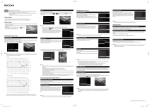
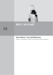
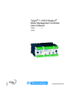
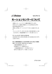
R010
V2.0
What are the main parameters on
TeSysT ?
I- Type of publication
Typical application
Level 2 use
Best know Method (BKM)
Internal use
Troubleshooting guide
Customer
II- Product
- Product range :
- Product family :
TesysT
LTMR
III- Introduction
This document describes you which are the main parameters to control before downloading a
configuration on TesysT. You can find a complete description for all functions in the user manual. These
Prints Screen match with PowerSuite V2.5.0.0 and Patch V2.1 available on Schneider electric website.
Page 1/9
R010
V2.0
IV- Description
Product Settings
Select current range, Network and Control
voltage.
If AC control voltage, set the Input configuration
according to Control voltage
Page 2/9
R010
V2.0
Motor and Control Settings 1/3
Motor parameters
For each operating mode:
•2w Control: maintained
•3 w Control: impulse
If Custom operating mode,
set the Custom ID of your
Custom logic
Allow automatic transitions for:
•reverser (Forward Reverser)
•2 speed (Low High)
After count down of Transit Time
Link of 2 step operating
mode if star delta
To limit the number of starts
during a short period by
imposing a timeout between 2
consecutive starts (0= no
restriction).
Optional parameter. Limit the max FLC setting
to the Contactor rating
If unused , keep the value by default (810A)
For 2 step operating mode: Transit time starts
counting down upon the earlier of the 2
parameters
Note: important parameters in red
Page 3/9
R010
V2.0
Motor and Control Settings 2/3
Local terminal trip inputs via hard wired
input devices or Local HMI commands via
HMI port
Bump: O1 and O2 are opened or remain
open when changing control mode
Bumpless: O1 and O2 keep their original
position when changing control mode
Select Reset mode according to your need
to Manual, Automatic or Remote
When Reset Mode set on Automatic set
the parameters for each group. See group
definition in the User manual
Note: important parameters in red
Page 4/9
R010
V2.0
Motor and Control Settings 3/3
Note: important parameters in red
•If internal ground fault detection, select
None
•If external ground fault detection, select
the CT ratio in the list or select other ratio
and type your CT values
Example: 2500:1
primary turns=2500
secondary turns=1
•If internal CT use, select None
•If external CT use , select the CT ratio in the list or
Select other ratio and type your CT values
Example: 250:1 primary turns:250; second. turns:1
Select the number of passes you have done in the CT
windows of LTMR to improve the measure accuracy
Wiring Error detects:
•CT reversal wiring
•Phase configuration fault
•Motor temperature sensor wiring fault
ON-OFF Diagnostic detects Control/command problems:
(Start Command Check, Run Check Back, Stop Command
Check ,Stop Check Back)
Page 5/9
R010
V2.0
Thermal Settings 1/2
•Inverse thermal: I²t principle. Use this selection
by default
•Definite time: only for special use. With this
setting , the long start protection must be enabled
Parameters linked to Define time Trip type
•DefDtime: delay of the protection function.
Bypassed during start stage.
•DefOtime: overcurrent time
If selected, divide the
cooling period by 4 in
Inverse thermal only
Adapt the trip class
according to the motor
application
FLC setting:
FLC1: Motor Full Load Current
FLC2: Motor High Speed Full Load Current
These parameters are linked to product range,
Load CT ratio, number of passes and contactor
rating.
Scroll up or down the % of FLC to obtain the
close value in Amps
Note: important parameters in red
Page 6/9
Reset level = after thermal trip, possible to restart
motor only if thermal capacity under this level
Adapt parameters according to your application
R010
V2.0
Thermal Settings 2/2
Fault & warning validation
Select type of sensor
Select Fault & Warning level
according to application (Motor)
Protection setting principle
Protection name
Fault time: Delay for the Fault
signalling
Fault & Warning validation
Fault level: signals a fault after time
delay if level crossed over
Warning level: signals a warning without
time delay if level crossed over
Note: principle identical for other current, voltage, power and power factor protection
Page 7/9
R010
V2.0
Communication setting
Allow configuration
from Network
Byte order for double word:
Bigendian for XBTN410
Network Comm Loss
management
Note : Same principle for HMI setting
Page 8/9
R010
V2.0
HMI Display setting
Contrast of display
Display Selection by parameter type
Note: it is more efficient to select a short list
of relevant parameters rather than selecting to
much parameters
Page 9/9
HMI Language selection