1
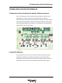
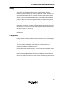
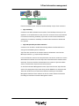
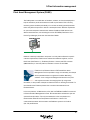
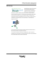
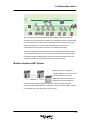
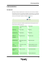
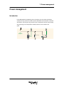
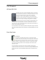
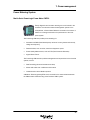
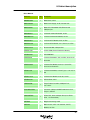
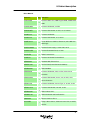
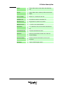
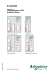
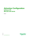
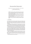
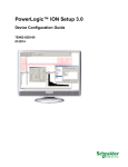
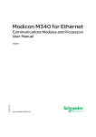
How can I...
build my Collaborative Control Platform
System Technical Guide
2
Table of Contents
1
Introduction....................................................................... 4
2
Collaborative control architecture .................................. 7
3
Plant information management ..................................... 11
4
Collaborative control...................................................... 19
5
Motor control................................................................... 27
6
Instrumentation............................................................... 31
7
Power management........................................................ 34
8
Cabinet description ........................................................ 37
Glossary ................................................................................. 54
3
1-Introduction
Introduction
Definition
Collaborative Control Architecture is a solution platform built to facilitate the
implementation of collaborative control and information management functions.
Objectives
In “How Can I…”, the architecture building project, several STGs (System Technical
Guide) have been tested and validated on “Collaborative Control Architecture
Solution Platform”. This concise and readable document has been created to help the
reader acquire a comprehensive understanding of this platform. All sectional
architectures and components deployed in this platform are introduced.
4
1-Introduction
Document Overview
This document starts with an analysis of customer requirements for automation
architecture in Chapter 2, Collaborative Control Architecture. Based on this, the 5
sectional architectures provided by Schneider Electric are explained in the following
chapters:
•
Chapter 3, Information Management: Plant operation data acquisition and
analysis
•
Chapter 4, Collaborative Control: PLC (Programmable Logic Controller) and I/O
system
•
Chapter 5, Motor Control: Motor control, protection, monitoring and metering
•
Chapter 6, Instrumentation: Measurement devices
•
Chapter 7, Power Management: Power distribution, supply and monitoring
Note: All sectional architectures are interconnected.
The CCA solution platform is installed in 6 cabinets. Chapter 8, Cabinet Description
completes the description of the platform.
5
1-Introduction
How to Use This Guide
This document is complimentary reading for the “How Can I…” STGs (System
Technical Guides) about the CCA solution platform.
No technical details about designing applications on this Collaborative Control
Architecture are described here. Readers can get these contents from the related
STGs available on the Schneider Electric Village portal: http://the-village.schneiderelectric.com/Business_Offer/Solutions_EndUsers/SiteMgr.nsf/.
With a full and correct understanding of both the Collaborative Control Architecture
and customer constraints, readers can modify this platform to build customized
architectures.
The product descriptions in this document do not replace other Schneider Electric
related User Manuals or technical publications.
There is a glossary to help you understand the terms used in this document at the
end.
Safety Notice
The standards and level of safety you apply to your system is determined by its
design and the extent to which your system may be a hazard to people and
equipment. Building a system based on the architectures introduced in this document
does not relieve the user from adhering to, the relevant national and international
safety laws and regulations.
6
2-Collaborative Control Architecture
Collaborative Control Architecture
Collaborative Control Architecture Solution Platform Overview
The CCA (Collaborative Control Architecture) Solution Platform is based on a full
understanding of customer requirements by Schneider Electric. Both highperformance offers (automation & power distribution) and advanced network and field
bus technologies are integrated to fulfill these automation architecture requirements.
The key principles deployed for the design of the “Collaborative Control Architecture
Power
Management
Plant information network
SCADA
servers
Historian
servers
Instrumen- Motor
control
tation
Collaborative
control
Plant
information
management
Solution Platform” are introduced below.
Layered Architecture
Layered Architecture is one of the key customer requirements during the system
design phase. Depending on the different collaborative control and information
management functions, different products should be assigned to different sections to
enable flexible interconnection and interoperability within and between sections.
7
2-Collaborative Control Architecture
The CCA uses this “Layered Architecture” concept. Schneider Electric provides
answers for all 5 functional sections:
1) For the Plant Information Management Section, Schneider Electric provides:
a) Ampla as MES (Manufacturing Execution System) software
b) Vijeo Citect as SCADA (Supervisory Control and Data Acquisition) software
c) Vijeo Historian as the report generation and publication tool
d) The FactoryCast family for enhanced traceability using the Web service
2) For the Collaborative Controller Section, depending on the size of control
system, Schneider Electric provides the Modicon Quantum, Premium and M340
PLC controllers. All these PLCs (Programmable Logic Controllers) are
programmed by the same Unity Pro software.
3) For the Motor Control Section, Schneider Electric provides the ATV (AlTiVar)
VSDs (Variable Speed Drives) and TeSys Motor Starters to manage motor and
pump control. The PowerSuite software can be used to configure the ATV drives,
TeSys U starter and TeSys T controller.
4) For the Instrumentation Section, nearly all the intelligent instrumentations can be
integrated into CCA with the Profibus PA field bus.
5) For Power Management Section, Schneider Electric provides APC UPSs.
Uninterruptible Power Supplies to momentarily sustain power supply to data
servers and PowerLogic meter to monitor the alternating power in automation
system.
Transparency
Transparency is an architecture requirement for communication within or between
sections. Based on network or field bus technology, all cabling system (switches,
gateway, etc.) become invisible, which makes the communication among devices
seems to be point-to point. Then the architecture designer can configure the
communication without extra programming.
Ethernet is widely used as intranet, industrial control networks and field buses in the
CCA. Based on common TCP/IP protocols, managers and plant operators can easily
access real-time data from the plant via SCADA or HMIs (Human Machine Interfaces).
All the networks, field buses and devices are transparent to them.
Except for these, the majority of Schneider Electric Ethernet offers are embedded
with the web technology. By viewing web pages stored in the Ethernet devices with
8
2-Collaborative Control Architecture
any standard web browser, management and operation staff can immediately get
configuration and diagnostic information about these devices.
Diversity
Diversity sets high requirements for system flexibility. For the same control functions,
based on customer constraints, suitable architecture using different products must be
provided.
Depending on the scalability of the control system, midrange PLCs Modicon M340,
Premium, and the high end PLC Modicon Quantum are deployed in the CCA. The
Modicon M340 and Premium are more suitable for plant control, while the Modicon
Quantum has better performance in hybrid and process controls.
Depending on the motor control specifications, different types of motor control
architecture are provided in the CCA. TeSys U and TeSys T provide the DOL (Direct
On Line) control mode, which provides protection, metering and monitoring of the
motors while ATV 31 and 71 are Variable Speed Drives that can perform extra speed
controls.
Availability
Availability is a customer requirement for continuous production. Unexpected
production stoppage not only reduces the plant productivity but may also cause the
loss of assets and intermediate products. So, redundant architectures are commonly
deployed in key process sections to ensure uninterrupted production. Depending on
system availability requirements, stand-alone and Hot Standby architectures are
included in the CCA Platform. This high availability can be realized at different CCA
layers by using Ethernet Dual Rings, the Quantum / Premium HSBY (Hot StandBY)
controllers, redundant DIO (Distributed Input and Output) islands and redundant
drives & instrumentations.
9
2-Collaborative Control Architecture
Safety
Safety is the most critical requirement in some process industries, since any
malfunction in these industries may result in a catastrophic accident. Therefore, SISs
(Safety Instrumented Systems) are required to perform key safety control functions.
The IEC 61508 functional safety standard defines 4 System SILs(System Integrated
Levels) for safety, SIL1 to SIL4 (the highest). The IEC 61511 standard is a guide on
how to design and build a SIS for a process control application.
Depending on the SIL requirements safety and non- safety architectures are
integrated in CCA platform. Certified by TÜV Rheinland, Safety Quantum can provide
SIL2 protection to a process control. The Safety Quantum platform can communicate
with the Non-safety PLC platform, but
the interoperability between the platforms is strictly limited to avoid interference with
the safety part.
Compatibility
During expansion and retrofit phases, a reliable method must be provided to integrate
the newly designed architecture with existing systems. The expansion and retrofit
cost and the influence on the existing system must be minimized.
The CCA provides compatibility to nearly all devices, instrumentations and
architectures available from different providers.
Profibus DP/PA (Decentralized Periphery / Process Automation) is included to enable
the interconnection between the CCA and the devices in Profibus DP/PA installed
base. Furthermore, third party instrumentations (such as Endress + Hauser) and
PAMS (a Plant Asset Management System, such as FieldCare) are also integrated
into the CCA. With Ethernet and Profibus PA support, these third party offers can help
customers greatly reduce their operation and maintenance costs.
10
3-Plant information management
Plant information management
Introduction
In process automation applications, Vast quantities of data about Plant Operation
Data, Maintenance Data and Quality Data need to be collected to make synchronized
analysis. The goal is to increase productivity and profitability.
Plant information
management
MES
Operator workstation
Operator workstation
Historian
Asset management
Printer
Web client
RAS
SCADA
servers
Historian
servers
Schneider Electric Information Management architectures include MES and SCADA
functions. The MES software Ampla, which will be integrated into the CCA platform
later, is briefly introduced… Then a detail description about Vijeo Citect, Vijeo
Historian, FactoryCast and PAMS are provided.
Ampla
MES are used to reveal opportunities for improved business
performance and increased profit margins. MES solutions
enable corporate, IT (Information Technology), plant and
production managers to improve OEE (Overall Equipment
Effectiveness) and increase production and profitability by
transforming and presenting real-time information into a business context throughout
the enterprise.
Ampla adopts a non-invasive, modular approach. It leverages open technologies to
complement existing automation and IT systems. Ampla solutions are deployed in a
modular fashion, where each module delivers specific benefits to aid in improving
each business need independently. Each module has a targeted purpose with a focus
on returning a measurable ROI (Return of Investment) in key areas such as
production, quality, traceability and downtime. Data is stored in an open, industry
standard database such as MS SQL or Oracle, thus allowing seamless integration
with existing business infrastructure and reporting systems, complying with IT
requirements and further reducing the cost of ownership.
11
3-Plant information management
Ampla can integrate the modules together and, along
deploying new modules, provides an exponential increase
in value.
In the CCA platform several modules are selected to perform the following MES
functions:
•
Ampla Metric: Calculation and generation of KPIs (Key Performance Indicators)
•
Ampla Production: Analysis of real time data and generation of reports
•
Ampla Quality: Analysis, reporting and managing of product quality
•
Ampla Inventory: Management and tracking of inventory and material movement
•
Ampla Planner: Bridging the gap between ERP (Enterprise Resources Planning)
systems and plant floor systems (e.g., SCADA)
•
Ampla Knowledge: Creation of a knowledge repository to store all operator
experience
Scada and HMI
This part of the installation is dedicated for the control and the supervision of the CCA.
Vijeo Citect
Vijeo Citect is a SCADA product provided by Schneider Electric. It
is a library-integrated and object-oriented development environment.
Thanks to this architectural advantage, high flexibility is provided to
customers during application development.
12
3-Plant information management
Operator workstation
Plant information network
SCADA
servers
From the architecture point of view, the intrinsic flexibility of Vijeo Citect is shown in:
•
High availability
Customers can define redundant servers (Alarm, Trend and Report servers) for one
application. In the SCADA Server mode, more than one monitor client can be defined
to increase the monitoring availability. Vijeo Citect can also connect Dual Ethernet
architecture to increase the availability of communication between the SCADA and
PLC systems.
•
High interoperability and interconnection
Customers can use OPC to enable data exchange between SCADA and PLCs or
among several SCADA systems via Ethernet.
Vijeo Citect also performs as the interface between collaborative control and the
MES-layer software, e.g., Ampla and Vijeo Historian.
In the CCA Platform, there are two enterprise-class rack servers (“machine” is used to
differentiate the hardware server and Vijeo Citect functional servers created on these
machines). These two machines are dedicated to the creation of Vijeo Citect Alarm
Servers, Trend Servers, Report Servers and I/O Servers.
On the Plant Information Management intranet, Vijeo Citect Servers, Vijeo Historian
Servers, iPC (designed as Vijeo Citect Client) and the PAMS PC are interconnected.
These two machines are connected to the Ethernet Dual Ring via ConneXium
Management Switches. These switches are also the routers between the Ethernet
Dual Rings and the Plant Information Management intranet.
13
3-Plant information management
Because Vijeo Citect provides high flexibility to the architecture design, two possible
architectures are proposed depending on the system availability requirements:
•
Single Server
In the Singer Server architecture, only one of the two machines is attached to the
Ethernet Dual Ring. Only one set of Vijeo Citect Alarm, Trend, Report and I/O servers
is defined. It is connected to two ConneXium Managed Switches located on different
Ethernet Rings to enable high-available communication with the PLCs.
•
Redundant Server
In the Redundant Server architecture, the maximum availability based on Vijeo Citect
is assured. Both machines are connected to an Ethernet Dual Ring via different
Ethernet ports. Redundant Vijeo Citect functional servers (Alarm Server, Trend
Server, Report Server and I/O Servers) are created on the machines.
The communication between Vijeo Citect and Unity Pro can be through ModNet or
OFS(OPC Factory Server). ModNet can only be used when all variables from Unity
Pro are located variables, OFS does not have this limitation. For more details about
how to configure ModNet and OFS communication, please refer to the related STGs.
Vijeo Designer
Vijeo designer is a design tool for the simplest control application
up to high-end HMI installations. It is specifically designed for
configuring the Magelis® XBT-GT graphic terminals, Smart iPC and
Compact iPC.
Magelis HMI
In the CCA platform, a Magelis panel is installed. The goal of this
panel is to simulate different faults for the application running on
this platform.
14
3-Plant information management
Vijeo Historian
Vijeo Historian is a Report Design, Generation and Publishing tool.
It helps optimize data usage by providing a powerful, enterprisewide reporting tool that collects, records and delivers meaningful
reporting data from multiple and disparate systems. Using the
information provided by Vijeo Historian, more effective decisions
can be made to optimize operational performance.
Plant information netwo rk
Historian
servers
Comprising Historian and portal functionality, Vijeo Historian empowers IT systems
with accurate data storage and long term reports. All these reports can be accessed
and visualized through Vijeo Historian Portal, Microsoft Excel and Reporting Service.
Vijeo Historian provides tools for reporting customization and connection to SQL
Server 2005. More Advanced report designs and user application development can
be done in Microsoft Visual Studio 2005.
In the CCA Platform, Vijeo Historian works with Vijeo Citect to provide high
traceability of operational data. Vijeo Citect is the unique data resource for Vijeo
Historian. Although Trend and Report servers can be defined on the SCADA server,
the capacity of historical data storage on the server is very limited. As a complement,
Vijeo Historian provides magnitude historical data and reporting schemes that fulfill
customer requirements for historical data management.
One machine acting as the Vijeo Historian Server is connected to the Plant
Information Management intranet. It shares the same engineering station with 2 other
SCADA servers located on the same intranet. All databases managed by the userdefined SQL Server are stored on this server. Published information is visible to
operators (if they have access rights) by using any web browser.
15
3-Plant information management
Plant Asset Management System (PAMS)
The PAM system is a combination of hardware, software, and services deployed to
help the workforce predict and assess the health of plant assets. This is done by
monitoring asset conditions periodically or in real time to identify potential problems
before they affect the process or lead to a catastrophic failure. With the requirement
for open and transparent communication between PAMS and field devices from
different manufacturers, new technologies such as FDT/DTM (Field Device Tool /
Device Type Manager) have been introduced into PAMS.
Plant information network
PAMS is a relatively independent component in a CCA platform. Based on specific
customer requirements, PAMS can be selected from different suppliers, such as
PACTware (PACTware e.V.), FieldCare (Endress + Hauser) and FDT Container
(M&M Software). In the CCA platform, Fieldcare is chosen as the PAMS.
FieldCare is an Endress+Hauser's FDT based Plant Asset
Management Tool that provides a range of functionality from simple
device parameterization to engineered Condition Monitoring
solutions. It can configure all intelligent field devices in the plant
and supports customers in managing them. By using status
information, it also provides a simple but effective means of checking their health. For
more details about FieldCare please refer to technical documentation from
Endress+Hauser.
In the CCA platform, a PAMS station (a PC) that has FieldCare installed is connected
to Plant Information Management intranet. All instrumentation maintenance jobs are
operated from this station. The only instrumentation in the CCA platform is a
thermoresistor TR24 PT100 Temperature from Endress + Hauser. The
communication between this instrument and FieldCare system is via Profibus
(PA / DP) and Ethernet.
16
3-Plant information management
Web Services
Schneider Electric offers a wide range of
TR (Transparent Ready) products:
Controllers and PLCs, industrial PCs,
HMI devices, Variable Speed Drives,
Distributed I/O modules, Gateways, Web servers, Switches, SCADA software,
inductive identification systems, etc. These products provide different levels of Web
services and communication services over Ethernet TCP/IP, according to user
requirements. With these embedded web services, customers can easily access or
customize the product information, such as maintenance / real-time data and
diagnostic information.
In the TR approach, Ethernet modules and Web gateways offer different levels of
Web services (Standard, Configurable and Active).
To increase the architecture maintenance and diagnostics, many TR offers are
integrated into the CCA Platform. The table below lists the offers in the CCA Platform
that provide TR Web Services and their related Class.
17
3-Plant information management
Description
M340 CPU, with Ethernet/ CANopen Ports
Premium HSBY CPU
Web Service
Class B
Class C
x
x
x
Premium ETY module 10/100 Ethernet, Webserver
Quantum HSBY CPU
Quantum Safety Stand-alone CPU, SIL2
x
x
x
Quantum NOE module, 10/100 Ethernet Webserver
Advantys STB standard NIM, Ethernet Port
Magelis XBT GT 7.5”
x
x
Ethernet Card for ATV 71
x
Predefined (Class B) or use-defined (Class C) web pages can be visited via the IP
addresses of the offers in the table above. All the data can be accessed using any
Web browser that supports embedded Java code. The standard functions provided by
the Web server are supplied “ready-to-use” and, therefore, do not require any
programming of either the PLC or the client PC device supporting a Web browser.
For more details about the functions provided by TR offers, please refer to Schneider
Electric “Transparent Ready” User Manual.
18
4-Collaborative control
Collaborative control
Introduction
Collaborative Control is the architecture designed to answer customer requirements
for process controllers. In this architecture, the key questions to answer are how to
choose controllers, how to set up communication among controllers and enable
communication between controllers and devices/instrumentations.
Collaborative
control
Engineering
CANopen
Ethernet
Profibus
Ethernet
In this chapter, CCA platform architectures are described to answer these questions.
Ethernet Dual Ring
The ConneXium switches are used in the CCA platform to form the Ethernet dual ring.
The Ethernet dual ring
architecture ensures that
whenever one communication
path is blocked, an alternative
path can be used to access the
destination Ethernet node. Switch operations, such as configuration, diagnostics and
traffic management should be managed and reported by network management tools.
For the ConneXium, these operations are performed by ConneXview software, which
can greatly increase the efficiency of network management.
19
Plant
information
management
4-Collaborative control
Plant information network
Collaborative
control
SCADA
servers
The CCA platform provides customer with high availability solutions on different
automation layers. The Ethernet Dual Ring is the redundant architecture implemented
on the controller layer. Communication between controllers and components (Vijeo
Citect, Vijeo Historian) on the Plant Information Management section and
communication among controllers are done via the Ethernet Dual Ring.
The Ethernet Dual Ring comprises six 8-port ConneXium Managed Switches. Three
of the ConneXium switches form one of the two redundant Ethernet rings. Except for
iPC, Modicon M340 and XBTGT HMI, all other controllers and SCADA servers are
connected simultaneously to two switches located on different rings.
Modicon Quantum HSBY System
Modicon Quantum is a High End
controller designed for process control.
ETY-Sync
CPU-Sync
It provides optimum cycle times.
Additional communication functions,
diagnostics, memory flexibility and
data storage are integrated in Modicon Quantum. The Hot Standby Controller
provides a high-available solution for customers. Switching from the primary controller
to the standby one can be done within one scan cycle.
20
4-Collaborative control
In the CCA Platform,
the two sets of
Quantum HSBYs are
installed in cabinets.
They represent two
major architectures that
can be deployed on the
Quantum HSBY
Platform. The first is
based on Profibus DP,
the second on the Ethernet field bus.
In the “Quantum HSBY + Remote Quantum I/Os islands” architecture, communication
between the CPU and Remote I/O is based on the S908 protocol, which uses CRP
and CRA modules.
The “redundant controller + non-redundant RIO Island” architecture is deployed. On
each CPU Rack one CRP RIO adapter is installed, but there is only one CRA RIO
Drop on the RIO rack. A splitter is required to connect the CRA module to the CRP
modules on both racks.
By installing Prosoft PTQ modules on each CPU rack, a Profibus DP ring is formed.
All Profibus DP compatible devices, such as the Advantys STB with Profibus DP NIM
(STB NDP 2212), VSD ATV 71, TeSys T motor management controller can be
connected to the Profibus DP field bus. Furthermore, communication between
Quantum HSBY controller and instrumentations on Profibus PA field bus can be done
by adding a Profibus DP/PA segment coupler to this ring.
A Quantum NOE Module (Ethernet Communication Module) and a ConneXium
Ethernet Switch can form an Ethernet Ring. Since Ethernet provides a more open
and flexible network backbone, any Ethernet device can connect to this ring. In the
CCA platform, communication between the Quantum HSBY and the VSD ATV 71 and
the Advantys STB Island uses this Ethernet ring.
21
4-Collaborative control
Modicon Premium HSBY System
The Premium HSBY is a cost effective, Hot
Standby solution provided by Schneider
Electric. It inherits the Unity Premium I/O and
ETY - sync
communication architectures. For migration, it
CPU - sync
is only necessary to retrofit the CPU (to a TSX
H57 24M or TSX H57 44M) and update the system to a redundant architecture. High
system availability can be enhanced by deploying a redundant distributed I/O system
via Ethernet Modbus TCP. The Premium HSBY must be configured and programmed
by Unity Pro V3.1 or later versions.
In the Premium HSBY architecture, except for the CPU-sync done through dedicated
ports on the CPUs, an extra ETY-sync architecture is mandatory for non-ambiguous
diagnosis. On each CPU rack a “Monitored ETY” module (TSX ETY 4103 / 5103) is
installed. It is connected directly or via Ethernet switches. The communication
between the two monitored ETY modules is mandatory during CPU switchover. For
more details, please refer to “Premium HSBY User Manual”.
In the CCA platform, the high-end HSBY CPU
TSX H57 44M is chosen as the controller. On each CPU
rack a Monitored ETY module, two ETY modules (for
communication with Ethernet Dual Ring) and I/O modules
are installed.
To communicate with devices via Ethernet, the two
Monitored ETY modules also perform the role of I/O
scanners. A managed ConneXium Ethernet switch is
deployed to build a star topology. An Advantys STB Island
with a Ethernet NIM (STB NIP 2212) and VSD ATV 71 are
connected to this Ethernet switch.
22
4-Collaborative control
Modicon M340 System
The Modicon M340 is a mid-range controller provided by
Schneider Electric . Two communication ports with
different protocols are embedded in Modicon M340 CPU
Module. CANopen, Ethernet and Modbus communication
are available via these ports. An extra SD card for CPU
and a NOE (Ethernet Communication Module) can increase data storage capacity
and performance of the whole system.
With the CPU-embedded ports and M340 NOE module, the Modicon M340 can
perform the role of an Ethernet node or a CANopen / Modbus Master. Therefore, a
customized system can be built based on these protocols.
In the CCA Platform, the CANopen extension
power of M340 is highlighted. A CPU with
embedded CANopen and Ethernet ports
(P34 CPU 2030) is used as the controller. An
Advantys STB Island with CANopen NIM (STB
NCO 2212) is connected to CANopen as the DIO.
Since motor control is widely used in mid-range
controller applications, a TeSys T motor
management controller and VSD ATV 31 are
integrated into this CANopen architecture.
The Modicon M340 can be configured and
programmed by Unity Pro 3.0 or later versions.
CANopen communication for the Modicon M340
can be directly configured in Unity Pro.
23
4-Collaborative control
Safety Quantum System
The Safety Quantum PLC is the safety process controller
provided by Schneider Electric. TÜV Rheinland has certified this
controller with SIL2 protection for process control. The Safety
Quantum reuses the architecture of Quantum Platform.
When building a Quantum Safety platform, several restrictions must be taken into
account:
1. To eliminate malfunctions of Safety I/O modules caused by non-safety I/O
modules, only Quantum Modules that are defined as “Non-inference Modules”
are allowed in a safety architecture. For a detail list of Non-inference Modules,
please refer to “Safety Quantum User Manual”.
2. For the Safety Quantum only Unity Pro XLS can be used for configuration and
programming.
3. Only LD and FBD can be used as programming languages (for other non-safety
controllers, all 5 languages defined in IEC 61131-3 are available).
4. Only the Safety Functional Block is allowed. DFBs (Derived Function Blocks) are
strictly forbidden in the safety program sections.
In the CCA Platform, the simplest “single CPU + single
field bus + single RIO Island” architecture is chosen. On
the CPU rack, a Stand-alone safety controller
140CPU65160S is mounted with two NOE modules for
dual Ethernet communication and some safety I/O
modules (140 SDI 953 00S and 140 SDO 953 00S). The
140 CRP 931 00 and 140 CRA 931 00 couple use the
S908 protocol for communication. Be careful that S908
field bus is not a safety field bus, which means it makes
no contribution to the PFD/PFH decrease of a SIS. And on the RIO rack, several
safety modules are installed to perform the input / output role of the safety functions.
24
4-Collaborative control
Engineering Tools
In the CCA platform an engineering station is needed to support all the software used
by the architecture. Its main tasks include:
•
Development of PLC applications
•
Configuration of devices and instrumentations
•
Parameters assignment for equipment
The main softwares are listed below:
UNITY PRO is used for development of PLC applications.
25
4-Collaborative control
UAG (Unity Application Generator) is a system design tool for
automatic generation for the Unity Pro and SCADA applications.
The Advantys configration software is network interface
and I/O configuration tool for Advantys STB islands.
The PowerSuite Software Workshop makes it easy to
configure Telemecanique variable speed drives and starters
such as:
-Tesys U starter
-TeSys T motor management controller
- ATV VSD Variable Speed Drive
- ATS Soft Starter
26
5-Motor control
Motor control
Introduction
Motors are widely used to drive pumps, fans, conveyors and other moving devices.
The objective of Motor Control is to ensure that the motor can output user-expected
drive to equipment to make them work properly.
In the CCA platform, Motor Control has 2 modes: DOL Control and Variable Speed
Control. These modes are implemented via:
•
Direct On Line Control: the TeSys U Starter Controller and the TeSys T Motor
Management System
•
Variable Speed Controls: ATV 31 and ATV 71
For more details, please refer to STG “How Can I … Pump and Motor Management”.
Motor management system TeSys T
The TeSys T is a three-phase motor control & management unit
provided by Schneider Electric. It is used for motor control and
protection in harsh industrial applications, where downtime must
be avoided. When associated with a circuit breaker and contactor, the TeSys T can
perform its role as a management and protection unit.
27
5-Motor control
In these units, protection, metering and monitoring functions are integrated to ensure
the desired performance of motors. The main functions include:
•
Protection against thermal overload, phase imbalance or reversal, earth faults,
etc.
•
Metering and Monitoring of the current/voltage on the 3 phases, motor
temperature, history, etc.
•
The LTM R TeSys T version is equipped with a communication interface to allow
remote monitoring and control of the motor. The following networks are available:
Modbus, CANopen, DeviceNet, Profibus DP and Ethernet TCP/IP.
•
There are two sets of TeSys T units mounted in the CCA platform with different
communication protocols:
•
In the Modicon M340 system, TeSys T communicates with M340 Controller using
a CANopen field bus.
•
In the Quantum HSBY configuration, PTQ modules are deployed to set up a
Profibus DP ring. The TeSys T is integrated into this ring as a Profibus DP slave.
TeSys U Starter controller
TeSys U is a compact and modular motor starter controller. Because the
disconnect switch, SCPD (Short-Circuit Protection Device), contactor and
overload relay are integrated in the TeSys U, no external circuit breaker and
contactor is needed.
With its modularity features, the TeSys U provides high flexibility for motor
control architecture design. There are three main components in a TeSys U offer: the
Power Base (for electrical protection), Control Unit (3 types: Standard, Advanced and
Multifunction) and other function modules (such as Advantys STB communication
module, etc…)
In the CCA platform, the TeSys U motor control architecture is implemented through
Advantys STB Distributed I/O islands. In both the Quantum HSBY and Premium
HSBY architectures, Ethernet is deployed as the communication network between the
PLCs and devices. To make full use of the DIO architecture, an Advantys STB islands
with Ethernet NIM (STB NIP 2212) is connected to the Ethernet.
28
5-Motor control
The EOS (End Of Segment) module STB XBE 1100 is installed at the end of the
island segment to extend Advantys STB internal bus. The STB XBE 1100 can be
used to connect the desired TeSys U modules. Tthe internal field bus must be
terminated with the TeSys U termination (LU9RFL15).
For more details about the TeSys U modules used on a STB
bus extension, please refer to the “Advantys STB User Manual”.
ATV 31 Variable Speed Drive
The ATV 31 drive is a frequency inverter for squirrel cage asynchronous
motors. It is robust, compact and easy to set up. Drives are available for
motor ratings ranging from 0.18 kW to 15 kW for three phase motors and
0.18 kW to 2.2 kW for a single phase motors. The embedded CANopen
and Modbus ports can be used to communicate with remote display
terminals or PLCs. If other field buses or networks are used, then a gateway between
the field bus and CANopen or Modbus is mandatory.
For the ATV 31, PowerSuite software is suitable to configure the parameters of the
VSD. Unity Pro is needed to configure the communication between the ATV VSD and
the PLC from Schneider Electric.
In the CCA Platform, one motor control architecture, with an ATV 31, is deployed. The
ATV 31 VSD can communicate with the Modicon M340 via the CANopen field bus.
To connect the ATV 31 to a PowerSuite or another remote terminal, a CANopen TAP
VW3CANTAP2 is used. There are three RJ45 ports on this TAP, the first two
(ATV1and ATV2) can be connected to two ATV 31 drivers, the third one is exclusively
used for a PowerSuite or other remote terminal.
29
5-Motor control
ATV 71 Variable Speed Drive
The ATV 71 Drive provides rating ranges from 0.37 KW to 630 KW for
three phase motors and from 0.37 KW to 5.5 KW for single phase motors.
This drive can be used for controlling asynchronous motors in the sensor
/ sensorless flux vector control mode and synchronous motors with
sinusoidal electromotive force when there is no speed feedback.
The ATV 71 provides PWR (Power Removal) safety function, which allows a drive to
be installed as part of the safety system to ensure the safety of an industrial process.
This function also enables the ATV 71 drive to offer protection for motors that are
installed in an explosive atmospheres (ATEX).
For communications, the ATV 71 can connect to the main field buses and networks
(such as Profibus DP, Modbus TCP, Ethernet/IP, Modbus Plus, etc) via an extra
communication card.
For the ATV 71, PowerSuite software is suitable for configuring VSD parameters.
Unity Pro is needed to configure communication between the ATV VSD and PLCs
from Schneider Electric.
In the CCA Platform, three sets of ATV 71 Drives are installed:
1. With Premium HSBY / Quantum HSBY via Ethernet
As described in Chapter 4, Collaborative Control, in Premium HSBY and
Quantum HSBY architectures, Modbus TCP Ethernet is deployed as the field bus.
ATV 71 VSD is connected as an Ethernet node. A communication card (VW3 A3
310) is mounted on the plate of the ATV 71.
2. With Quantum HSBY via Profibus DP
In the architecture comprised by a Quantum HSBY, PTQ module and Profibus
DP, one set of ATV 71 VSDs is connected to the Profibus DP. A communication
card (VW3 A3 307) is mounted on the plate of the ATV 71.
The configuration of the ATV 71 on Profibus DP cannot be done directly with
Unity Pro. The Profibus DP configuration must be first generated with the Prosoft
Profibus DP configuration software and then Unity Pro can communicate with ATV 71
after importing this configuration file.
30
6-Instrumentation
Instrumentation
Introduction
With higher and higher requirements for accurate control, more and more traditional
instrumentations have been retrofitted with intelligent instrumentations. The traditional
4-20 mA wiring system is gradually being replaced by advanced instrumentation field
Instrumentation
buses, such as the HART, Profibus PA, Fieldbus Foundation, etc.
The table below compares the traditional 4-20mA instrument wiring system with the
advanced instrumentation field buses.
Conventional 4 -20 mA
Field network
system
Field wiring
Point-to-Point
Multi-Drop
Information flow
Unidirectional
Bidirectional
Quantity of
Single data value
Multi data value
Measurement numeric
Multiple data types
information
Information type
values
Control
Centered on a control
Optionally allotted to control
functionality
system
system and/or field devices
Maintenance
Mainly in the field
From a remote location
Corrective maintenance
Predictive maintenance
location
Maintenance type
31
6-Instrumentation
For more details, please refer to the STG “How Can I… Instrumentation
Management”
This document does not provide a complete view of modern field bus
instrumentation.Only an introduction to Profibus PA, the field bus instrumentation
deployed in the CCA Platform, is provided.
Profibus PA (Process Automation)
Profibus PA is a half-duplex, synchronous, self-clocking profile. Like other
instrumentation field buses, Profibus PA supports simultaneous transmission of
power and communication data via a single cable at 31.25 kbps. The most commonly
used Profibus PA architecture involves a Segment Coupler (DP/PA gateway) that
connects Profibus DP and Profibus PA segments.
Within this Profibus PA segment, a “Trunk and Spur” topology is deployed. The
maximum length of each segment is 1900 m and the maximum number of devices on
each segment is 32. All segments must be terminated with terminating resistors.
In the Profibus communication protocol, three communication channels are defined:
•
MS0: a cyclic communication (supported by DP-V0) channel between Profibus
Slave and DPM1 (Class 1 DP master)
•
MS1: an acyclic communication (supported by DP-V1 and DP-V2), channel
between Profibus Slave and DPM1 (Class 1 DP master)
•
MS2: an acyclic communication channel between Profibus Slave and DPM2
(Class 2 DP master)
Here, Profibus Slave means a field device. DPM1 is normally integrated into a PLC.
DPM2 is defined as a master that sets device parameters via acyclic communication,
e.g., PAMS. The MS2 channel is used almost universally for acyclic data transmission
for process automation devices.
Further information is provided in “How can I… Instrumentation Management”
32
6-Instrumentation
As described in Chapter 4, Collaborative Control, a
Profibus DP ring with PTQ modules is deployed in
the Quantum HSBY system. Profibus DP-V1 is
available in the PTQ module, which means
communication between instrumentation and a PLC
is via MS0 and MS1. In this architecture,
communication between instrumentation and PAMS
is via MS2. PAMS sets values and supervises
diagnostics of the instrumentation via the Ethernet
NOE modules on the PLC rack.
A SK1 Profibus segment coupler from PEPPERL + FUCHS is chosen to interconnect
Profibus DP and PA. In the CCA platform, only one instrument, a thermoresistor
TR24 PT100 Temperature from Endress + Hauser, is installed. This thermoresistor
connects to SK1 through a 2 wire cable that includes both device data transmission
and power supply.
33
7- Power management
Power management
Introduction
Power Management and Metering are an important part of the whole automation
architecture. they ensure the health of power distributed to all automation controllers
and devices. This Chapter only focuses on the 3 components used for power supply
and monitoring in the CCA platform. Global protection is not treated in this
guide.
Power
Management
Power supply
AC
PowerLogic
DC
34
7- Power management
Power Management
APC Smart-UPS SC 1000
The UPS is a key part in a power management system. To ensure the
normal operation of key devices in an automation architecture (such as
servers and controllers) when the utility power is momentarily
unavailable, a UPS is normally deployed to provide instantaneous
protection from power interruption. If sustaining the power supply for a
longer period is required, a standby power generator is mandatory.
The APC Smart-UPS SC 1000 is provided by Schneider Electric. The
SC 1000 provides a total of 600 Watts / 1000 VA to all loads. Both the input and
output are 120 V or 220 V. Typical backup time for a SC 1000 under a full load is 7.4
minutes; typical recharge time is 8 hours.
In the CCA platform, the SC 1000 UPS provides a backup power supply to all servers
(Vijeo Citect and Vijeo Historian) This contributes to increased availability of the entire
system.
Phaseo Power Supply
ABL8 Module
The majority of automation units need 24 or 12 VDC power supply.
Therefore, the power (either directly from the utility power network from a
UPS) must be first converted to direct current (DC) and then connected
to devices. In addition to voltage and AC/DC conversion, a universal power supply
must provide the primary protection to ensure the quality of the entire DC power
distribution network.
In the CCA platform, both 24 VDC and 12 VDC are needed to supply power to
controllers and other devices; therefore, a Universal Power Supply (ABL8RPS24100)
module and a DC/DC conversion (ABL8DCC12020) module are integrated into the
platform.
35
7- Power management
Power Metering System
Merlin Gerin PowerLogic Power Meter PM750
Timely diagnostic and accurate metering are crucial criteria in the
evaluation of an electrical network management system. In the
CCA platform, a Power Meter PM750 is mounted on the surface of
Cabinet 2 to manage and monitor the performance of the CCA
power system.
The PowerLogic PM 750 provides power metering for:
•
Instantaneous RMS (Root Mean Square) values of current (phases and neutral),
voltage and frequency
•
Demand values, such as active, reactive and apparent power
•
Power Quality Measurement, such as THD (Total Harmonic Distortion)
•
Signed Power Factor
The PowerLogic PM 750 also provides management and supervision for the electrical
system, such as
•
Data Recording (min/max instantaneous value)
•
Alarms with under/over conditions and I/O status
•
Communication via the Modbus protocol
A Modbus / Ethernet gateway ETG 100 is mounted for the communication between
the PM750 and the Ethernet Ring of the Premium HSBY system.
36
8-Cabinet description
Cabinet description
Cabinet 1: M340 + CANopen
15
1
2
7
3
8
ATV 1
A TV2
PowerSuite
4
9
5
6
13
11
12
10
220VAC
24VDC
CANopen
14
Ethernet
Intenal Bus
1
TeSys GV2 Main Circuit Breaker
2
Circuit Breaker for PLC
3
Circuit Breaker for Phaseo
4
LC1D Line Contactor
5
LC1D Contactor for ATV 31
6
LC1D Contactor for TeSys T
7
Phaseo ABL8 24VDC Power Supply
8
Modicon M340 PLC
9
CANopen TAP
10
Advantys STB DIO island with CANopen NIM
11
TeSys T Motor Management Controller
12
Magelis XBTN Operator Panel
13
ATV 31 Variable Speed Drive
14
Motor
15
ConneXium 8 Port Managed Switch
37
8-Cabinet description
Bill of Material
Reference
Qty
Description
BMXXBP0600
1
M340 Rack, 6 slots
BMXCPS2000
1
M340 Power Supply, 20 W, 100-240 VAC
BMXP342030
1
M340 CPU, Embedded USB, Ethernet and
CANopen port
BMXAMI0410
1
4 Channel Isolated AI Module, 16 bits
BMXAMO0210
1
2 Channel Isolated AO Module, 16 bits
BMXDDI1602
1
16 Channel DIT Module, Sink, 24 VDC
BMXDDO1602
1
16 Channel DO Module, 0.5 A, Source, 2 4 VDC
STBNCO1010
1
Economical NIM, CANopen Port
STBPDT3100
1
24 VDC PDM (Power Distribution Module)
STBXBA2200
1
STB PDM Base
STBDDI3230
STBDDO3230
STBACI1230
1
1
1
2 Channel DI Module, Sink, 24 VDC, Short-Circuit
Protection
2 Channel DO Module, Source, 2 A, 24 VDC,
Over-current Protection
2 Channel AI Module, Current Type, 0…20 mA, 12
bits
STBACO1210
1
2 Channel AO Module, 0-20 mA, 12 bits
STBXBA1000
4
STB I/O Base, Size I
LTMR08CFM
1
TSXCANKCDF90
TeSys T Motor Controller, CANopen Port,
100…240 V
Connector CANopen SUBD Female 90 for PLC,
TeSys U, STB I/O
VW3CANTAP2
XBTZ938
XBTN410
1
1
1
ATV31 TAP, three CANopen Port (2 for ATV31
Drive, 1 for PowerSuite)
Magelis Connecting Cable
Matrix screen, 4 line * 20 character, Uni-TE,
Modbus, 24 VDC
38
8-Cabinet description
VW3CANCARR1
1
VSD ATV 31 Connection Cable, 1M
ABL8RPS24100
1
Single-phase or 2-phase 10 A, 240 W
ATV31H018M2
1
VSD ATV 31, 0,18KW, 3P, 200…240 VAC
TCSESM083F23F0
1
ConneXium 8TX Ethernet Switch
BMX XCA USB H018
1
M340 cable for point to point connection
39
8-Cabinet description
Cabinet 2: Premium HSBY + Ethernet
8
7
17
1
18
2
3
6
16
4
15
9
10
220VAC
12
5
24VDC
11
13
10VDC
Ethernet
Modbus
AdvSTB
interal Bus
14
1
TeSys GV2 Main Circuit Breaker
2
Circuit Breaker for PLC
3
Circuit Breaker for Phaseo
4
LC1D Line Contactor
5
LC1D Contactor for ATV 71
6
Phaseo ABL8 24VDC Power Supply
7
Phaseo ABL8 12VDC Power Supply
8
Meter
9
Modicon Premium HSBY
10
ConneXium 5 Port Unmanaged Switch
11
Advantys STB DIO island with ETH NIM
12
TeSys U Motor Starter
13
ATV 71 Variable Speed Drive
14
Motor
15
PowerLogic PM750 Power Meter
16
ETG 100 Modbus/Ethernet Gateway
17
ConneXium 8 Port Managed Switch
18
Magelis HMI 7.5''
40
8-Cabinet description
Bill of Material
Reference
TSXH5744M
Qty Description
2
Premium HSBY CPU, 2MB Program RAM, 440KB DATA
RAM
TSXDEY08D2
2
8 Channel DI Module, 24 VDC
TSXDSY08T2
2
8 Channel DO Module, 24 VDC, 0.5 A, isolated
TSXAEY414
2
4 Channel AI Module
TSXASY410
2
4 Channel AO Module, 10 V, 20 mA
TSXETY5103
6
10/100 M Ethernet Module, Webserver (with 8 MB User
Web Page)
TSXPSY2600M
2
Premium Power Supply, 110/220 VAC, 26 W
TSXRKY12EX
2
Premium Extendable Rack, 12 Slots
TSXTLYEX
2
BUSX Terminal Sets
TSXBLY01
8
Premium I/O Module Terminal Block
STBNIP2212
1
Standard NIM, Ethernet Port
STBPDT3100
1
24 VDC PDM (Power Distribution Module)
STBXBA2200
1
STB PDM Base
STBDDI3230
STBDDO3230
1
1
2 Channel DI Module, Sink, 24 VDC, Short-Circuit
Protection
2 Channel DO Module, Source, 2 A, 24 VDC, Overcurrent Protection
STBACI1230
1
2 Channel AI Module, Current Type, 0…20 mA, 12 bits
STBACO1210
1
2 Channel AO Module, 0-20 mA, 12 bits
STBXBA1000
4
STB I/O Base, Size I
STBXBE1100
1
STB EOS Module with Bus Extension
VW3A3310
1
Ethernet Card for ATV 71
LUCC05BL
1
TeSys U Motor starter, Advanced Control Unit, 0.55 KW,
24 VDC
41
8-Cabinet description
LUB12
LULC15
1
1
TeSys U Motor starter, Power Base, Non-Reversing,
12 A
TeSys U Motor starter, Advantys STB Communication
Module
ATV71HU22M3
1
VSD ATV 71, 2.2 KW, 3P, 220 VAC
499NES25100
1
5-Port Ethernet Switch 10/100 Base-TX
ABL8RPS24100
1
Single-phase or 2-phase 10 A, 240 W
ABL8DCC12020
1
7...15 VDC, 2 A Converter Module
XBTGT4230
TCSESM083F23F0
PM750MG
UNYXCAUSB033
XBTZG935
1
1
1
1
1
7.5'', 4096 colors, STN, CF Card Slot, USB, Ethernet
Port
ConneXium 8TX Ethernet Switch
PowerLogic Power Meter, Modbus Port, THD and
min/max readings
Premium/ Quantum USB cable for point to point
connection
Cable for XBGT Magelis and PC
42
8-Cabinet description
Cabinet 3: Quantum HSBY + Profibus DP
8
7
1
18
2
3
6
4
10
5
220VAC
9
16
24VDC
11
14
10VDC
15
Ethernet
12
S908
QTM Sync
13
17
Profibus DP
Profibus PA
1
TeSys GV2 Main Circuit Breaker
2
Circuit Breaker for PLC
3
Circuit Breaker for Phaseo
4
LC1D Line Contactor
5
LC1D Contactor for ATV 71
6
Phaseo ABL8 24VDC Power Supply
7
Phaseo ABL8 12VDC Power Supply
8
Meter
9
LC1D Contactor for TeSys T
10
Modicon Quantum HSBY
11
Quantum Remote IO
12
Pepperl-Fuchs SK1 Segment Coupler
13
Endress + Hausser Thermoresistor
14
ATV 71 Variable Speed Drive
15
TeSys T Motor Management Controller
16
Advantys STB DIO island with DP NIM
17
Motor
18
ConneXium 8 Port Managed Switch
43
8-Cabinet description
Bill of Material
Reference
Qty
Description
140XBP01000
2
Quantum Rack, 10 Slots
140XBP00600
1
Quantum Rack, 6 Slots
140CPS12420
140CPU67160
140NOE77111
3
2
2
Quantum Power Supply, 115/230 VAV, Redundant,
11 A
Unity Quantum HSBY CPU
Quantum FactoryCast Web Server Ethernet 10/100M
Module
140DDI35300
2
32 Channel DI Module, 24 VDC, 4 groups isolated
140DDO35300
2
32 Channel DO Module, 24 VDC, 0.5 A per Channel
140AVO02000
2
4 Channel AI Module, Voltage
140CRP93100
2
RIO Head, S908, Single Port
PTQ-PDPMV1
2
Quantum PROFIBUS DP/DPV1 Master Modules
(incl. config SW)
140CRA93100
1
Quantum RIO Drop, S908, Single Port
MA 0186 100
1
SPLITTER
RPX KIT 6F
1
Cable extension CPU / SPLITTER
RPX KIT CRP
1
Cable extension Rack extension / SPLITTER
490 NOR 000 03
1
Cable extension coprocessor to coprocessor
140DAI74000
1
16 Channel DI Module, 230 VAC, isolated
140DAO84000
1
16 Channel DO Module, 24-230 VAC, isolated, 4 A
per Channel
STBNDP2212
1
Standard NIM, Profibus DP Port
STBPDT3100
1
24 VDC PDM (Power Distribution Module)
STBXBA2200
1
STB PDM Base
STBDDI3230
1
2 Channel DI Module, Sink, 24 VDC, Short-Circuit
Protection
44
8-Cabinet description
STBDDO3230
1
2 Channel DO Module, Source, 2 A, 24 VDC
STBAVI1270
1
2 Channel AI Module, +/- 10 V, 12 bits
STBACO1210
1
2 Channel AO Module, 0-20 mA, 12 bits
STBXBA1000
4
STB I/O Base, Size I
LTMR08PFM
1
TeSys T Motor Controller, CANopen Port,
100…240 V
ATV71HU22M3
1
VSD ATV 71, 2.2 KW, 3P, 220 VAC
VW3A3307
1
ATV 71 Profibus DP Communication Card
KFD2-BR-1.PA.93
1
Pepperl + Fuchs SK1 Profibus DP/PA segment
coupler
TR24PT100Temperature
1
Endress + Hauser Thermoresistor
ABL8RPS24100
1
Single-phase or 2-phase 10 A, 240 W
ABL8DCC12020
1
7...15 VDC, 2 A Converter Module
TCSESM083F23F0
1
ConneXium 8TX Ethernet Switch
UNYXCAUSB033
490NOC00005
499NOS27100
1
1
1
Premium/ Quantum USB cable for point to point
connection
Fiber Converter / RJ45 cable
Converter fiber cable from HSBY Quantum to
converter
45
8-Cabinet description
Cabinet 4: Quantum HSBY + Ethernet
7
8
1
16
2
3
6
4
9
220VAC
14
5
24VDC
13
10VDC
11
12
Ethernet
S908
10
QTM Sync
AdvSTB
interal Bus
15
1
TeSys GV2 Main Circuit Breaker
2
Circuit Breaker for PLC
3
Circuit Breaker for Phaseo
4
LC1D Line Contactor
5
LC1D Contactor for ATV 71
6
Phaseo ABL8 24VDC Power Supply
7
Phaseo ABL8 12VDC Power Supply
8
Meter
9
Modicon Quantum HSBY
10
Quantum Remote IO
11
ConneXium 5 Port Unmanaged Switch
12
ATV 71 Variable Speed Drive
13
TeSys U Motor Starter
14
Advantys STB DIO island with ETH NIM
15
Motor
16
ConneXium 8 Port Managed Switch
46
8-Cabinet description
Bill of Material
Reference
Qty
Description
140XBP01600
2
Quantum Rack, 16 Slots
140XBP00600
1
Quantum Rack, 6 Slots
140CPS12420
140CPU67160
140NOE77111
140DDI35300
140DDO35300
3
2
6
2
2
Quantum Power Supply, 115/230 VAV,
Redundant, 11 A
Unity Quantum HSBY CPU
Quantum FactoryCast Web Server Ethernet
10/100M Module
32 Channel DI Module, 24 VDC, 4 groups
isolated
32 Channel DO Module, 24 VDC, 4 group
isolated, 0.5 A per Channel
140CRP93100
2
RIO Head, S908, Single Port
140CRA93100
1
Quantum RIO Drop, S908, Single Port
MA 0186 100
1
SPLITTER
RPX KIT 6F
1
Cable extension CPU / SPLITTER
RPX KIT CRP
1
Cable extension Rack extension / SPLITTER
490 NOR 000 03
1
Cable extension coprocessor to coprocessor
140DAI74000
1
16 Channel DI Module, 230 VAC, isolated
140DAO84000
1
16 Channel DO Module, 24-230 VAC, isolated,
4 A per Channel
STBNIP2212
1
Standard NIM, Ethernet Port
STBPDT3100
1
24 VDC PDM (Power Distribution Module)
STBXBA2200
1
STB PDM Base
STBDDI3230
STBDDO3230
1
1
2 Channel DI Module, Sink, 24 VDC, ShortCircuit Protection
2 Channel DO Module, Source, 2 A, 24 VDC,
Over-current Protection
47
8-Cabinet description
STBAVI1270
1
2 Channel AI Module, +/- 10 V, 12 bits
STBACO1210
1
2 Channel AO Module, 0-20 mA, 12 bits
STBXBA1000
4
STB I/O Base, Size I
STBXBE1100
1
STB EOS Module with Bus Extension
LUCC05BL
LUB12
LULC15
1
1
1
TeSys U Motorstarter, Advanced Control Unit,
0.55 KW, 24 VDC
TeSys U Motorstarter, Power Base, NonReversing, 12 A
TeSys U Motorstarter, Advantys STB
Communication Module
ATV71HU22M3
1
VSD ATV 71, 2.2 KW, 3P, 220 VAC
VW3A3310
1
ATV 71 Ethernet Communication Card
ABL8RPS24100
1
Single-phase or 2-phase 10 A, 240 W
ABL8DCC12020
1
7...15 VDC, 2 A Converter Module
TCSESM083F23F0
1
ConneXium 8TX Ethernet Switch
UNYXCAUSB033
490NOC00005
499NOS27100
1
1
1
Premium/ Quantum USB cable for point to
point connection
Fiber Converter / RJ45 cable
Converter fiber cable from HSBY Quantum to
converter
48
8-Cabinet description
Cabinet 5: Quantum SIL 2 Standalone + Ethernet + S908
5
1
2
3
4
6
220VAC
7
24VDC
Ethernet
S908
1
TeSys GV2 Main Circuit Breaker
2
Circuit Breaker for PLC
3
Circuit Breaker for Phaseo
4
Phaseo ABL8 24VDC Power Supply
5
ConneXium 8 Port Managed Switch
6
Modicon Safety Quantum
7
Safety Quantum Remote IO
49
8-Cabinet description
Bill of Material
Reference
Qty Description
140XBP01000
1
Quantum Rack, 10 Slots
140XBP00600
1
Quantum Rack, 6 Slots
140CPS12420
140CPU65160S
140NOE77111
140SDI95300S
140SDO95300S
2
1
2
3
3
Quantum Power Supply, 115/230 VAV, Redundant,
11 A
Quantum Safety Stand-alone CPU, SIL2
Quantum FactoryCast Web Server Ethernet 10/100M
Module
Quantum Safety DI Module, 16 Channels, 24 VDC,
SIL2
Quantum Safety DO Module, 16 Channels, 24 VDC,
SIL2
140CRP93100
1
RIO Head, S908, Single Port
UNYXCAUSB033
2
Cable Extension CRP / CRA
140CRA93100
1
Quantum RIO Drop, S908, Single Port
ABL8RPS24100
1
Single-phase or 2-phase 10 A, 240 W
TCSESM083F23F0
1
ConneXium 8TX Ethernet Switch
UNYXCAUSB033
1
Premium/ Quantum USB cable for point to point
connection
50
8-Cabinet description
Cabinet 6: Plant Information Management System
3
1
5
2
4
7
6
7
4
8
220VAC
10
9
24VDC
Ethernet
Hard wire
1
Circuit Breaker
2
Phaseo ABL8 24VDC Power Supply
3
ConneXium 8 Port Managed Switch
4
APC Smart-UPS
5
Managed Switch
6
Dell PowerEdge R200 Server for VJC
7
Dell PowerEdge R200 Server for VJC
8
Dell PowerEdge R200 Server for VJH
9
Magelis Compact iPC
10
Dell PowerEdge 180AS Operator Panel
Bill of Material
Reference
MPCKT55NAX20**
Qty Description
1
Magelis Compact iPC, Pentium M 1.6 GHz,
16,777,216 colors
TCSESM043F23F0
1
ConneXium 4TX Ethernet Switch
Dell PowerConnect 2324
1
Dell 26-port Ethernet Switch
Dell PowerEdge R200
3
Dell Industrial PC
Dell PowerEdge 180AS
1
Dell Engineer Station
APC Smart-UPS SC 1000
1
APC UPS
51
8-Cabinet description
Network
Plant information network
SCADA
servers
9
9
9
SW5 (cabinet 1)
9
9
1
SW7 (cabinet 5)
SW6 (cabinet 3)
SW2 (cabinet 2)
9
SW3 (cabinet 6)
2
3
4
SW4 (cabinet 4)
5
6
7
8
Control and Switch Connection:
1
Embedded ETH port on M340 to SW5
2
TSX ETY 5103 Ethernet Module on Premium Primary Rack to SW2 and SW5
3
TSX ETY 5103 Ethernet Module on Premium Standby Rack to SW3 and SW6
4
140 NOE 711 00 Ethernet Module on Quantum Primary Rack to SW2 and SW6
5
140 NOE 711 00 Ethernet Module on Quantum Standby Rack to SW4 and SW7
6
140 NOE 711 00 Ethernet Module on Quantum Primary Rack to SW3 and SW6
7
140 NOE 711 00 Ethernet Module on Quantum Standby Rack to SW4 and SW7
8
140 NOE 711 00 Ethernet Module (on Safety Quantum Rack) to SW4 and SW7
9
Six 8-port ConneXium Managed Switches form the backbone of Ethernet Dual Rings
52
8-Cabinet description
Software
Software Name
PowerSuite
Unity Pro
Vijeo Citect
Vijeo Historian
Vijeo Designer
Advantys Configuration
Qty
1
Description
1
Configuration Software for ATV 31, 71 and
TeSys T and TeSys U.
Programming Software for Unity PLCs
1
SCADA Software
1
Report Generation Software
1
Magelis HMI Design Software
1
Advantys STB Configuration Software
1
Unity Pro and SCADA Application Generation
Software
Software
Unity Application
Generator
Comment: For software versions, please refer to specific System Technical Guide.
53
Glossary
Glossary
Acronym
ATEX
Description
The ATEX directive is two End User directives describing what equipment and work
environment is allowed in an environment with an explosive atmosphere.
CCA
Collaborative Control Architecture is a general name for system & architecture built by
all Schneider Electric Automation products, power products for industrial control and
3rd party products. The mission of CCA is to provide End User an advanced, flexible
and customized architecture.
Citect Client
Citect Client is a computer that accesses shared network resources provided by
another computer called a server. Vijeo Citect client-server based architecture is
designed to distribute the processing tasks and optimize performance.
Citect Server
Citect Server is a computer connected to an I/O device (or number of I/O devices).
When Vijeo Citect is running, the server exchanges data with the I/O device(s) and
distributes information to the other display clients as required.
DFB
A DFB (Derived Function Block) is a user function block that has been customized to
take the specific nature of your project into consideration. It can be stored in the UserDefined Library.
DIO
Distributed I/O is a kind of signal input/output unit installed in the field. The
communication between IO islands and CPU is via field buses on which IO islands are
defined as nodes.
DOL
DOL (Direct On Line) is the simplest motor control mode which only uses circuit
breaker and contactor to control the start/stop of motors.
DPM1
EC 61158-5: A controlling device which controls several DP-Slaves (field devices).
Usually programmable (logic) controllers or process control systems are hosts for
master class 1.
DPM2
IEC 61158-5: A controlling device which manages configuration data (parameter sets)
and diagnosis data of a DP-Master (Class 1). Additionally the DP-Master (Class 2)
can perform all communication capabilities of a DP-Master (Class 1).
Usually personal computers are hosts for DP Master Class2 for programming, setting
parameters, diagnosing, and monitoring purposes.
54
Glossary
DP-V0
IEC 61784-1: DP-V0 is the basic stage of the PROFIBUS DP communication protocol.
DP-V0 devices (master and slaves) perform the following basic functionalities:
- Cyclic exchange of I/O data between controlling and slave devices
- Device, Identifier (module) and Channel related Diagnosis
- Parameterization of DP-slaves
- Configuration of DP-slaves
DP-V1
DP-V1 is the first stage of extension of PROFIBUS DP after DP-V0. DP-V1 devices
shall comply with the following features:
- Device related diagnosis is replaced by status and alarms.
- The first three octets of the user parameterization data are now standardized
Optionally these devices may support:
- Acyclic communication (MS1, MS2)
- If alarms are used, MS1 shall be supported
DP-V2
DP-V2 is the second stage of extension of PROFIBUS DP after DP-V1. DP-V2
devices shall comply with the following features:
- Data Exchange Broadcast (DxB) for slave to slave communication
(publisher/subscriber principle).
- Isochronous Mode (time tick synchronized operating slaves, e.g. drives)
- Up- and/or download of Load Region Data (domains)
- Function Invocation
- Clock Control (synchronization within slaves) and Time Stamping
- Redundancy
ERP
An ERP system is a business support system that maintains in a single database the
data needed for a variety of business functions such as Manufacturing, Supply Chain
Management, Financials, Projects, Human Resources and Customer Relationship
Management.
An ERP system is based on a common database and a modular software design. The
common database can allow every department of a business to store and retrieve
information in real-time. The information should be reliable, accessible, and easily
shared. The modular software design should mean a business can select the modules
they need, mix and match modules from different vendors, and add new modules of
their own to improve business performance.
EU
End User is the entity (people or company) that directly use the product or service
provided by manufacturers or service providers
55
Glossary
FBD
The Function Block Diagram (FBD) is a PLC language defined by IEC 61131-3. It
describes a function between input variables and output variables. A function is
described as a set of elementary blocks. Input and output variables are connected to
blocks by connection lines. An output of a block may also be connected to an input of
another block
FDT
Field device tool technology standardizes the communication interface between field
devices and engineering or process monitoring systems (host). Previous solutions had
been proprietary and usually based on e.g. RS232 communication. The key feature of
FDT is its independence from the communication protocol and the software
environment of either the device or the host system. The host environment provides
an FDT "frame application" that defines a set of interfaces to the field devices
parameterization and diagnosis software, e.g. on a standard PC platform. Such a
software package with an FDT interface is called a Device Type Manager (DTM).
Key features are:
- nested communication across hierarchies through gateways and CommDTM
- storage and retrieval of field device related parameters or information with versioning
- central printing support across different field device software packages (DTM)
HART
The HART Communications Protocol (Highway Addressable Remote Transducer
Protocol) is an early implementation of Field bus, a digital industrial automation
protocol. Its claim to fame is that it can communicate over legacy 4-20 mA analog
instrumentation wiring, sharing the pair of wires used by the older system. According
to some, due to the huge installed base of 4-20 mA systems throughout the world, the
HART Protocol is one of the most popular industrial protocols today.
HSBY
Hot Standby is used as a failover mechanism to provide reliability in system
configurations. The standby part is active and connected as part of a working system.
When a key component fails, the standby part is switched into operation. More
generally, a hot standby can be used to refer to any device or system that is held in
readiness to overcome an otherwise significant start-up delay.
I/O Scanning
IO scanning is a scheme that periodically read or write to/from remote inputs/ouputs
on the Ethernet network, without requiring any specific programming.
56
Glossary
KPI
Key Performance Indicators (KPI) are financial and non-financial metrics used to help
an organization define and measure progress toward organizational goals. KPIs can
be delivered through Business Intelligence techniques to assess the present state of
the business and to assist in prescribing a course of action. The act of monitoring
KPIs in real-time is known as business activity monitoring. KPIs are frequently used to
"value" difficult to measure activities such as the benefits of leadership development,
engagement, service, and satisfaction. KPIs are typically tied to an organization's
strategy.
LD
The Ladder Diagram (LD) is a PLC language defined by IEC 61131-3. The structure of
an LD section corresponds to a rung for relay switching.
MES
Manufacturing Execution Systems (MES) are IT solutions that support the primary
production processes in a production plant. These applications close the gap between
ERP systems and production equipment control or SCADA (Supervisory Control And
Data Acquisition) applications. Nowadays, MES applications have become essential
to support both real-time production control as well as data collection and reporting
(“manufacturing intelligence”), required to improve production performance.
ModNet
The MODNET protocol supports TCP/IP communication with the Modicon
Quantum PLC and most MODBUS/TCP compatible devices. The maximum request
length for the MODNET protocol is 1920.
NonInterference
Module
In Safety Quantum Platform, all modules are divided into 2 categories. One category
is modules designed based on functional safety methodology and certified by TÜV
Rheinland. Another one is non-safety Quantum modules which can only perform nonsafety functions and do not result in malfunctions of safety modules. All the modules in
the second category are called "Non-Interference Module"
OEE
Overall equipment effectiveness (OEE) is a hierarchy of metrics which focus on how
effectively a manufacturing operation is utilized. The results are stated in a generic
form which allows comparison between manufacturing units in differing industries.
OEE measurement is also commonly used as a key performance indicator (KPI) in
conjunction with lean manufacturing efforts to provide an indicator of success.
OPC
Object-Linking and Embedding (OLE) for Process Control. OPC is designed to bridge
Windows based applications and process control hardware and software applications
that permits a consistent method of accessing field data from plant floor devices.
57
Glossary
PLC
A programmable logic controller is a digital computer used for automation of industrial
processes. Unlike general-purpose computers, the PLC is designed for multiple inputs
and output arrangements, extended temperature ranges, immunity to electrical noise,
and resistance to vibration and impact. Programs to control machine operation are
typically stored in battery-backed or non-volatile memory.
Process
Process control is a statistics and engineering discipline that deals with architectures,
Control
mechanisms, and algorithms for controlling the output of a specific process.
PWR
"Power Removal" is an embedded safety function for ATV61/71 which prohibits
unintended equipment operation. When Power Removal function is triggered, the
motor no longer produces torque.
ROI
In finance, return on investment (ROI) is the ratio of money gained or lost on an
investment relative to the amount of money invested. The amount of money gained or
lost may be referred to as interest, profit/loss, gain/loss, or net income/loss. The
money invested may be referred to as the asset, capital, principal, or the cost basis of
the investment. ROI is usually given as a percent rather than decimal value.
SCADA
A Supervisory Control and Data Acquisition is a system that sends commands to a
real-time control system to control a process that is external to the SCADA system.
This implies that the system coordinates, but does not control processes in real time.
SCPD
SIL
Short-Circuit Protection Device
Safety Integrity Level (SIL) is defined as a relative level of risk-reduction provided by a
safety function, or to specify a target level of risk reduction. In simple terms, SIL is a
measurement of performance required for a Safety Instrumented Function (SIF). Four
SIL levels are defined, with SIL4 being the most dependable and SIL1 being the least.
A SIL is determined based on a number of quantitative factors in combination with
qualitative factors such as development process and safety life cycle management.
The requirements for a given SIL are not consistent among all of the functional safety
standards.
58
Glossary
SIS
Safety Instrumented Systems (SIS) are composed of three main elements. Process
sensors (to detect process anomalies), logic solvers (to interpret the information, and
to provide proper responses) and final control elements (to actuate or respond to
hazards). Altogether, these components are designed to respond to industrial plant
conditions that themselves may be hazardous or if no action is taken could eventually
result in a hazardous condition and to respond to a detected hazardous condition by
initiating pre-defined actions that either prevent the hazard or mitigate the hazards
consequences.
SQL
SQL (Structured Query Language) is a database computer language designed for the
retrieval and management of data in relational database management systems
(RDBMS), database schema creation and modification, and database object access
control management.
THD
The total harmonic distortion, or THD, of a signal is a measurement of the harmonic
distortion present and is defined as the ratio of the sum of the powers of all harmonic
components to the power of the Fundamental frequency.
TR
“Transparent Ready” is a family of Schneider Electric products developed based on
universal Ethernet TCP/IP and Web technologies which can be directly integrated into
automation applications. Create open solutions that are ready for collaboration,
ingenious installations that are easy to develop, operate and maintain, and flexible,
optimized automation architectures that can keep up with developments.
TÜV
TÜVs (short for Technischer Überwachungs-Verein, Technical Monitoring Association
Rheinland
in English) are German organizations that work to validate the safety of products of all
kinds to protect humans and the environment against hazards. And TÜV Rheinland is
one of its 4 subsidiaries.
UAG
Unity Application Generator is an advanced design and generation software tool that
integrates multiple PLCs and HMI/SCADA systems to provide an automation solution
similar to a Distributed Control System. UAG deploys ISA 88 batch control
architecture and object library idea. Part of Unity Pro and SCADA application can be
generated by using this tool.
UPS
An uninterruptible power supply (UPS), also known as a continuous power supply
(CPS) or a battery backup is a device which maintains a continuous supply of electric
power to connected equipment by supplying power from a separate source when
utility power is not available.
59
Glossary
VSD
A Variable Speed Drive (VSD) is a system for controlling the rotational speed of an
alternating current (AC) electric motor by controlling the frequency of the electrical
power supplied to the motor.
WSBY
Warm Standby is also a standby architecture. But comparing with HSBY, the transfer
time from primary to standby unit takes longer time, normally it is around several
seconds.
60
Schneider Electric Industries SAS
Head Office
89, bd Franklin Roosvelt
92506 Rueil-Malmaison Cedex
FRANCE
Due to evolution of standards and equipment, characteristics indicated in texts and images
in this document are binding only after confirmation by our departments.
Print:
www.schneider-electric.com
Version 1 - 10 2008