1
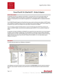
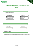
R033
1.0
How to Read&Write information with
TeSysT&U on Allen Bradley PLC?
I- Type of publication
Typical application
Level 2 use
Best know Method (BKM)
Internal use
Troubleshooting guide
Customer
IIII- Product
- Product range :
TeSysT/TeSysU
- Product family :
LTMR
IIIIII- Introduction
This document will describe you how to read and write datas with TeSysT&U on a network
DeviceNet through a PLC Allen Bradley. The CPU is a Logix 5561 and the communication card is a 1756DNB. We describe you how to read/write information with cyclic/acyclic (Class Instance Attribute request)
services (we put in attachment the file of RsLogix5000 with the program).
We advise you to work on this document with the technical resolution “R031_How to configure a
TeSysT on DeviceNet” or “R032_How to configure a TeSysU on DeviceNet” (available on the same web
page). We consider that the network is already operational and ready for data exchange between the master
card and the slaves connected.
You have to install RsLogix5000 (software for Allen Bradley PLC - V13.00 minimum)
Link for “R031_How to configure a TeSysT on DeviceNet”:
www.schneider-electric.com : Products and Services / Motor Control (on left side) / TesysT / Download /
Resolution
Link for “R032_How to configure a TeSysU on DeviceNet”:
www.schneider-electric.com : Products and Services / Motor Control (on left side) / TesysU / Download /
Resolution
Page 1/11
R033
1.0
IVIV- Description
Step 1: RsLogix5000: Configuration of the PLC
1.1.) Hardware configuration
Open RsLogix5000 and configure a PLC with CPU Control Logix 5561 and Communication card
1756-DNB:
a
b
c
You select the rack
corresponding to your
configuration: 4 slots, 7
slots, 10 slots …
After you can validate by
“OK”
You select the network
card for the PLC to
exchange information
between TesysT&U and
the PLC: “1756-DNB”
e
d
Right click:
“New module”
Page 2/11
R033
1.0
f
You select the
firmware revision of
the 1756-DNB card (it
is written on the side
of the card)
Enter a name for
your network card
g
You put in attachment the file of RsNetworx
that you use for your network configuration.
Into the RSNetWorx file (format *.dnt), you
have defined the entire configuration for your
slaves (TesysT&U) and communication card
(1756-DNB).
For more information feel free to read the
R031 or R032 (In the link of this document
you can find the ‘dnt’ file for example.
h
Once click on “Finish” button, the hardware configuration will be ended and you will be ready to
program requests to read or write information between TeSysT&U and the PLC Allen Bradley.
Page 3/11
R033
1.0
In our example the RsNetworx file is made with two slaves: TeSysT address 1 and TesysU address
2. TesysT&U exchange on the network are defined as follow:
- TesysT: Input data: DW (Double Word) 0 and DW1 / Output data: DW0 and DW1
- TesysU: Input data: DW2 and DW3 / Output data: DW2 and DW3
Note: The network speed is 125 kbps.
1.2.) Transfer of the configuration
There is a key in front of the CPU:
Each time you want to download an application you have to put on “Prog” position (right side). Now you can
process to the downloading operation: Go on the menu Communications / Enter on Line / Load
After downloading you put the key on “Run” position (CPU is in Run mode) and the program is
launched. For the DeviceNet card master you have to activate an internal bit of the card to put the devicenet
network in Run mode (the devicenet card will go “Idle” mode to “Run” mode):
0 => 1
Slot card number for
DeviceNet master: in
my example slot 1
Page 4/11
R033
1.0
Step 2: RsLogix5000: Read information from TeSysT/U
2.1.) Read cyclic data
We select the instance 110 for reading information into RSNetWorx software.
The cyclic exchange is an exchange automatically managed between the communication card and
the slaves. You do not need to use request, into the PLC, to access to the cyclic information. By default
TesysT&U send, all the time, information registers 455, 456, 457 and 458 (you can change the information
sent on cyclic network: see R031. On TeSysU you cannot customize this part, it is only on TeSysT).
You can read the value of these registers for TesysT into the live list tags of the CPU into
RsLogix5000 (you have to be connected):
‘1’ is the slot number of
the DeviceNet card.
“I” means input data of the
PLC for the slaves
Reg. 456
Reg. 455
Reg. 458
Reg. 457
DW0
DW1
2.2.) Read acyclic data (CIA request)
You have seen above that you can read four informations (for example: registers 455, 456, 457 and
458). You can read more informations but you have to use the acyclic service. The acyclic communication
allows you to access of all other informations remaining into the TeSysT&U. The acyclic service uses the
Class Instance Attribute format (CIA).
You have to program a request into RsLogix5000 to read the values of registers. For example, we try to read
registers 606 (Trip Class of TeSysT) and 541 (Time transition between Output 1 and Output 2 of TeSysT).
Open a routine to program your request (LADDER language):
Page 5/11
R033
1.0
Click on the left side of the program, dial “MSG” on your keyboard and press “Enter” thus a message
box occurs:
a
Write “MSG” and press “Enter”
b
This box “message” is a block used to program acyclic request in CIA format. Into the user manual of
TesysT DeviceNet April 2008 you can find all registers and their address in CIA format (pages 420 to 452).
Link for User manual TesysT DeviceNet April 2008:
http://www.global-download.schneiderelectric.com/852575030043326A/all/3A734120F9E60152C125746F0031859C/$File/1639504_02a55.pdf
(Note: the downloading can take few minutes)
In our example the registers that we want to read are 606 and 541 so the CIA addresses for these
registers are (provided into the user manual page 439 and 443):
Reg. 606 (Tripping class value):
Class = 6A
Instance = 01
Attribute = 07
Reg. 541 (Transition time between Output 1 and Output 2):
Class = 69
Instance = 01
Attribute = 02
You have to enter these addresses into two blocks message (one for each information read).
For Register 606:
You have to define a name for different tags. We need one tag for the message box and one tag
where you will receive the value read by the PLC from the TeSysT.
Page 6/11
R033
1.0
Right click on
“controller tag” and
select “New tag”
Block_Reading_Trip_Class
d
f
c
MESSAGE
e
You repeat ‘c’, ‘d’, ‘e’ and ‘f’ to create the tag “Reading_Trip_Class” with a Data Type “INT” (16 bits).
On each message box we need two tags as before.
After you can allocate the tags configured before and entered into the function block “MSG”:
g
In English “Get one attribute”
Code for reading one
information
(See user manual page 400:
link on page 6)
DeviceNet address for register
606 (See page 6)
Tag defined before to receive
the information read into the
register 606.
Page 7/11
R033
1.0
h
You define the hardware link
of the DeviceNet Master port:
in my PLC I have the card on
the slot 1 port 1 (but I had to
put slot “2” because it is the
only number that RsLogic
takes account)
After you repeat the steps ‘c’ to ‘h’ to create block to read register 541 (Transition time between
Output 1 and Output 2):
Page 8/11
R033
1.0
You can read these two registers value into the tags “Reading_Trip_Class” and “Reading Time
transition” by the way of an animation table (be sure to be online between your laptop and your PLC):
i
Class: 5
Time: 10
sec
Step 3: RsLogix5000: Write information from TeSysT/U
2.1.) Write cyclic data
We select the instance 100 for writing information into RSNetWorx software.
The cyclic exchange is an exchange automatically managed between the communication card and
the slaves. You do not need to use request, into the PLC, to write this cyclic information. By default
TesysT&U receives from the PLC, all the time, information registers 704, 703 (only for TesysU, for TesysT it
is reserved) and 700.
You can write the value of these registers to TesysT in the live list tags of the CPU into RsLogix5000
(you have to be connected):
‘1’ is the slot number of
the DeviceNet card.
“O” means output data of
the PLC to the slaves.
Reserved
Reg. 704
(command of
the outputs)
DW0
DW1
Reg. 700
(free register
for custom
mode)
Page 9/11
R033
1.0
2.2.) Write acyclic data (CIA request)
You have seen above that you can write two or three informations (registers 704, 703 (only for
TesysU and 700). You can write others informations (for configuration) but you have to use the acyclic
service. The acyclic communication allows you to access of all other informations remaining into the
TeSysT&U. The acyclic service uses the Class Instance Attribute format (CIA).
Also do not write information already available in the cyclic part: 704, 703 and 700. If you write 704, 703 or
700 by an acyclic request automatically the value wrote will be refreshed by the cyclic exchange.
You have to program a request into RsLogix5000 to write the values of registers. For example, we try to
write register 541 (Time transition between Output 1 and Output 2 of TeSysT).
Open the same routine (routine for reading acyclic data) to program this request (LADDER language).
Please to follow exactly the same steps as pages 5, 6 and 7:
(Create tags: “Block_Writing_Time_Transition” and “Writing_time_transition”)
a
In English “Define one attribute”
Code for Writing one
information
(See user manual page 400:
link on page 6)
DeviceNet address for register
541 (See page 6)
Tag defined to write the
register541.
Page 10/11
R033
1.0
b
You define the hardware link
of the DeviceNet Master port:
in my PLC I have the card on
the slot 1 port 1 (but I had to
put slot “2” because it is the
only number that RsLogic
takes account)
You can write this register (541) value into the tag “Writing_Time_Transition” by the way of an
animation table (be sure to be online between your laptop and your PLC):
You can write
Time transition of
the register 541
Page 11/11