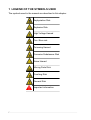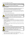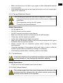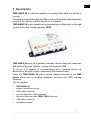
1
en
ENGLISH...............................................................5
2
en
SUMMARY
Introduction........................................................................................5
1 LEGEND OF THE SYMBOLS USED...........................................6
2 GENERAL SAFETY REGULATIONS..........................................7
2.1 Glossary..........................................................................................7
2.2 Operator Safety Regulations...........................................................7
2.2.1 General Safety Regulations................................................................7
2.2.2 Risk of Asphyxiation............................................................................7
2.2.3 Risk of Impact and Crushing...............................................................8
2.2.4 Hazards Caused by Moving Parts......................................................8
2.2.5 Risk of Burning or Scalding................................................................8
2.2.6 Fire and Explosion Hazard.................................................................9
2.2.7 Noise Hazard......................................................................................9
2.2.8 High Voltage Hazard...........................................................................9
2.2.9 Poisoning Hazard.............................................................................10
2.3 General User and Maintenance Warnings....................................11
3 SPECIFIC RULES FOR THE SAFETY IN THE INSTALLATION OF
TMD NANO 24................................................................................12
3.1 Glossary........................................................................................12
3.2 General Rules...............................................................................12
3.3 Operator Safety.............................................................................12
3.4 Safety Precautions........................................................................13
3.5 Safety during the Installation.........................................................15
4 ENVIRONMENTAL INFORMATION..........................................16
5 OPERATION OF THE TOOL'S RADIO DEVICES.....................17
6 INFORMATION REGARDING REGULATIONS.........................18
7 Description.................................................................................19
7.1 Image of the Device......................................................................20
7.2 Technical Features........................................................................21
8 INSTALLATION..........................................................................22
3
8.1 Installation precautions.................................................................23
8.2 Suggestions for Correct Installation..............................................24
8.3 OBD Connector Location..............................................................24
8.4 Protection tabs removal................................................................25
8.5 TMD NANO 24 positioning............................................................25
8.6 Power supply connections - Power supply cable 3903929...........26
8.7 Connections for the Diagnosis .....................................................27
8.7.1 Diagnosis cable EOBD 3900844......................................................27
8.7.2 Diagnosis cable EOBD FMS 3902044..............................................28
8.7.3 Diagnosis adaptor cable 3904487....................................................29
8.7.4 Diagnosis Adapter cable for Air Platforms 3904762.........................30
8.8 Checking the Installation...............................................................31
9 CONFIGURATION.....................................................................32
10 USE..........................................................................................33
10.1 ....................................................................................................33
10.2 Blink Code...................................................................................34
11 MAINTENANCE.......................................................................35
12 LEGAL NOTICES.....................................................................36
4
en
INSTALLATION MANUAL TMD NANO 24
Introduction
Dear Installer,
Please read through the instructions in this manual carefully and keep it for
future reference.
Reading and understanding the following manual will help you to avoid
damage or personal injury caused by improper use of the product to which
it refers.
TEXA S.p.A reserves the right to make any changes deemed necessary
to improve the manual for any technical or marketing requirement; the
company may do so at any time without prior notice.
This manual should be considered an integral part of the product to which
it refers. In the case it is resold the original buyer is therefore required to
forward the manual to the new owner.
Reproduction, whole or in part, of this manual in any form whatsoever
without written authorization from the producer is strictly forbidden.
© copyright and database rights 2010. The material contained in this
document is protected by copyright and database rights. All rights reserved
according to law and international agreements.
5
1 LEGEND OF THE SYMBOLS USED
The symbols used in the manual are described in this chapter.
Asphyxiation Risk
Explosion Risk
High Voltage Hazard
Fire / Burn risk
Poisoning Hazard
Corrosive Substances Risk
Noise Hazard
Moving Parts Risk
Crushing Risk
General Risk
Important information
6
en
2 GENERAL SAFETY REGULATIONS
2.1 Glossary
•
•
•
Operator: qualified person responsible for installing the tool.
Device: the purchased product.
Workplace: the place where the operator must carry out her/his work.
2.2 Operator Safety Regulations
2.2.1 General Safety Regulations
•
•
•
•
•
•
•
The operator must be completely clear-headed and sober when using the
device; taking drugs or alcohol before or while operating the device is strictly
forbidden.
The operator must not smoke during device operation.
The operator must carefully read all the information and instructions in the
technical documents provided with the tool.
The operator must follow all the instructions provided in the technical
documents.
The operator must make sure she/he is working in an environment which is
suitable for the operations that must be carried out.
The operator must report any faults or potentially hazardous situation in
connection with the workplace or the device.
The operator must carefully follow the safety regulations required for the
workplace in which she/he is working in and for the operations she/he has
been asked to carry out.
2.2.2 Risk of Asphyxiation
Exhaust gases from internal combustion engines, whether petrol
or diesel, are hazardous to your health and can cause serious
harm to your body.
Safety Precautions:
•
•
The workplace must be equipped with an appropriate ventilation and air
extraction system and must be in compliance with standards according to
current national laws.
Always activate the air extraction system when working in closed
environments.
7
2.2.3 Risk of Impact and Crushing
The vehicles which are undergoing A/C system recharging
operations and the devices must be properly blocked during
service, using the specific mechanical brakes.
Safety Precautions:
•
•
•
•
Always make sure that the vehicle is in neutral gear (or that it is set in parking
position in case of a vehicle equipped with automatic transmission).
Always activate the hand brake or parking brake on the vehicle.
Always block the wheels on the vehicle with the specific mechanical brakes.
Make sure the device is stable, on a flat surface and that the wheels are
locked with the specific brakes.
2.2.4 Hazards Caused by Moving Parts
Vehicle engines include parts that move, both while running and
when off (ex: the cooling fan is controlled by a thermal switch in
connection with the coolant temperature and can be activated
even when the vehicle is off), that can injure the operator.
Safety Precautions:
•
•
•
•
Keep hands away from moving parts.
Disconnect the engine cooling fan each time the engine you are working on
is still hot. This will avoid the fan from being unexpectedly activated even
when the engine is off.
Do not wear ties, loose clothes, wrist jewellery or watches when working on
a vehicle.
Keep connection cables, probes and similar devices away from the moving
parts of the engine.
2.2.5 Risk of Burning or Scalding
The parts that are exposed to high temperatures in engines that
are running or have just stopped could burn the operator.
Remember that catalytic mufflers reach very high temperatures,
able to cause serious burns or even start fires.
Acid in the vehicle batteries is another potential hazard.
Safety Precautions:
•
•
8
Protect your face, hands, and feet by using suitable protection.
Avoid contact with hot surfaces, such as spark plugs, exhaust pipes,
radiators and connections within the cooling system.
en
•
•
Make sure there are no oil stains, rags, paper or other inflammable material
near the muffler.
Avoid splashing electrolyte on skin, eyes and clothes, as it is a corrosive and
highly toxic compound.
2.2.6 Fire and Explosion Hazard
The following are potential fires and/or explosion hazards:
•
•
•
The types of fuel used by the vehicle and the vapours released by
these fuels.
The refrigerants used by the A/C system.
The acid in the vehicle batteries.
Safety Precautions:
•
•
•
•
•
•
•
•
•
•
Let the engine cool.
Do NOT smoke near the vehicle.
Do NOT expose the vehicle to open flames.
Make sure that the electrical connections are all well insulated.
Collect any fuel that might have spilled.
Collect any refrigerant that might have spilled.
Make sure you are always working in an environment equipped with a good
ventilation and air extraction system.
Always activate the air extraction system when working in closed
environments.
Cover the openings of the batteries with a wet cloth in order to stifle the
explosive gases before proceeding in testing or recharging.
Avoid causing sparks when connecting cables to the battery.
2.2.7 Noise Hazard
Loud noises that may occur within the workplace, especially during
service operations, may damage the operator's hearing.
Safety Precautions:
•
Protect your ears with suitable protective ear wear.
2.2.8 High Voltage Hazard
The voltage supply from the mains that powers the devices in the
workplace and the voltage within the vehicle starter system are a
potential shock hazard to the operator.
9
Safety Precautions:
•
•
•
•
•
•
•
•
Make sure the electrical system in the workplace is compliant to current
national standards.
Make sure the device being used is connected to ground.
Cut off the power supply voltage before connecting or disconnecting cables.
Do NOT touch the high voltage cables when the engine is on.
Operate in conditions of insulation from ground.
Work with dry hands only.
Keep conductive liquids away from the engine while working.
Never leave tools on the battery in order to avoid accidental contacts.
2.2.9 Poisoning Hazard
The hoses used to extract the gases can release toxic gases,
dangerous to the operator if exposed to temperatures higher than
250 °C or in case of a fire.
Safety Precautions:
•
•
10
Contact a doctor immediately should you inhale these gases.
Use neoprene or PVC gloves when eliminating combustion deposits.
en
2.3 General User and Maintenance Warnings
When using the device or carrying out scheduled maintenance (ex.: fuse
replacement) on the device, carefully follow the information provided
below.
•
•
•
•
•
•
•
Do not remove or damage the labels and the warnings on the device; do
NOT in any case make them illegible.
Do not remove or block any safety device the purchased product is equipped
with.
Only use original spare parts or spare parts approved by the manufacturer.
Contact your retailer for any non-scheduled maintenance.
Periodically check the electrical connections of the device, making sure they
are in good condition and replacing any damaged cables.
Periodically check parts that are subject to wear and replace them if
necessary.
Do not open or disassemble the device.
11
3 SPECIFIC RULES FOR THE SAFETY IN THE
INSTALLATION OF TMD NANO 24
The technology used for the design and inspection of the manufacture of
the TMD NANO 24 diagnostic tools and related accessories, make them
reliable, simple and safe to install and use.
Personnel in charge of installing the remote diagnostic tools is required to
follow the general safety regulations and use the TMD NANO 24 tools and
related accessories for their intended use only. Furthermore, they are
required to carry out the maintenance as described in this manual.
3.1 Glossary
Operator: qualified person responsible for installing the remote diagnosis
tool.
Device: any TMD NANO 24 device.
Accessory: any optional device connected to TMD NANO 24.
Wiring: specific electric cables which are used to connect TMD NANO 24
to its accessories, to the power supply, to the antenna etc.
3.2 General Rules
•
•
The operator must have basic knowledge in mechanics, automotive, car
repairs and potential dangers that can occur during the installation
operations.
The operator must carefully read all the information and instructions in the
technical documents provided with the tool.
3.3 Operator Safety
Airbags inflate with great force and a device/accessory placed in
their expansion area may be projected towards the occupants of
the vehicle thus causing serious harm and injuries.
Safety Measures:
•
12
Do not place the device/accessory in the expansion area of any airbag.
en
The device/accessory has been manufactured so as to result
electrically safe and insulated.
It is nevertheless necessary to reduce the risk of electrocution.
Safety Measures:
•
•
Do not touch the device/accessory, the accessories and the wiring with wet
hands.
If the liquid should penetrate inside the device/accessory, immediately
disconnect the power supply wiring and contact the technical assistance.
3.4 Safety Precautions
The device/accessory has been designed for the use in specific
environmental conditions.
The installation and use of the device/accessory in environments
with temperature and moisture characteristics different from those
specified may impair its efficiency.
Safety Measures:
•
•
•
•
Collocate the device/accessory in dry places.
Do not expose or install the device/accessory near heat sources.
Position the device/accessory by making sure it can be properly ventilated.
Do not use corrosive chemicals, solvents or harsh detergents to clean the
device/accessory.
The device/accessory has been manufactured so as to result
mechanically resistant.
Careless use and excessive mechanical stress may impair its
efficiency.
Safety Measures:
•
•
•
•
•
Do not drop, shake or hit the device/accessory.
Do not place objects over the cables and do not bend them.
Do not perform any kind of intervention that may damage the device/
accessory.
Do not open or disassemble the device/accessory.
Make sure that the device and the possible accessories connected to it are
firmly secured before the handling of the vehicle on which they are installed.
13
The device/accessory was designed so as to be electrically safe
and to work with specific power supply voltage levels.
Failure to comply with the specifications related to the power
supply may impair their efficiency.
Safety Measures:
•
•
•
•
Do not wet the device/accessory with water or other liquids.
If not otherwise specified, use the tool on vehicles with a 12/24V DC power
supply and the chassis connected to the negative pole.
The power supply of the device/accessory must be always connected
according to the procedures indicated in this manual.
Do not use external batteries to power the device/accessory.
The electromagnetic compatibility tests carried out on the device
guarantee that it can be adapted to the technologies normally used
on vehicles (e.g.: engine check, ABS, airbag etc.). Nevertheless,
if malfunctions occur you should contact the vehicle dealer.
In particular, the correct functioning of the device/accessory may
be impaired by covering the antenna with shielding objects and/or
materials.
The presence of such materials force the device/accessory to work
with a power higher than the normally necessary one.
Safety Measures:
•
14
Do not cover the device/accessory with shielded objects or materials.
en
3.5 Safety during the Installation
Make sure that the power supply devices (auxiliary batteries) are
disconnected and that they remain so during the entire installation
before proceeding with the installation itself.
Make sure that none of the electric cables, wiring in general, fuel
hydraulic pipes and safety pneumatic devices are damaged during
the installation.
Make sure that the installation does not affect the correct
functioning of the vehicle controls, in particular brakes and, in
general, all safety devices.
For the installation please exclusively use the wiring and the
components provided with the device/accessory.
15
4 ENVIRONMENTAL INFORMATION
For information regarding the disposal of this product please
see the pamphlet supplied.
16
en
5 OPERATION OF THE TOOL'S RADIO DEVICES
Wireless connection with Bluetooth, WiFi and HSUPA technology
Wireless connectivity through Bluetooth, WiFi and HSUPA is a technology
that supplies a standard, reliable method for exchanging information
between different devices using radio waves. Many other products besides
those built by TEXA use this technology, such as mobile phones, portable
devices, Computers, printers, cameras, Pocket PCs etc.
The Bluetooth, WiFi and HSUPA interfaces search for compatible
electronic devices based on the radio signals they emit and establish a
connection. TEXA tools only select and prompt compatible TEXA devices.
This does not exclude the presence of other sources of communication or
disturbance.
THE EFFICIENCY AND QUALITY OF BLUETOOTH, WiFi AND HSUPA
COMMUNICATION MAY BE AFFECTED BY THE PRESENCE OF RADIO
DISTURBANCE. THE COMMUNICATION PROTOCOL IS DESIGNED TO
MANAGE THESE TYPES OF ERRORS; HOWEVER, IN SUCH CASES
COMMUNICATION MAY BE DIFFICULT AND CONNECTION MAY
REQUIRE SEVERAL ATTEMPTS.
SHOULD THE WIRELESS CONNECTION ENCOUNTER SERIOUS
PROBLEMS AND COMPROMISE REGULAR COMMUNICATION, THE
SOURCE
OF
THE
ENVIRONMENTAL
ELECTROMAGNETIC
DISTURBANCE MUST BE IDENTIFIED AND ITS INTENSITY REDUCED.
Position the tool so that the radio devices it is equipped with can work
properly. In particular, do not cover it with any shielding or metallic materials
in general.
17
6 INFORMATION REGARDING REGULATIONS
Declaration of Conformity
TEXA S.p.A. hereby declares that the TMD NANO 24 complies
with the essential requirements and with all further provisions
as defined by the 1999/5/EC regulation.
A copy of the complete Compliance Declaration can be obtained at:
TEXA S.p.A., Via 1 Maggio 9, 31050 Monastier di Treviso (TV), Italy
Antennas
This product was designed and tested for operation with the provided
antennas.
18
en
7 Description
TMD NANO 24 is a device capable of acquiring data while the vehicle is
running.
The data is acquired through an OBD socket or through another diagnostic
socket of the vehicle in which the device is installed.
TMD NANO 24 is also capable of communicating via Bluetooth or through
a cable with other tracking devices TEXA.
TMD NANO 24 acts as a gateway between vehicle diagnosis resources
and external devices capable of using this diagnosis data.
To do so, it is capable of communicating with a tracking device via
Bluetooth or through a cable, transmitting the acquired data.
Using the TMD NANO 24 with a remote diagnosis device of the TMD
series allows you to combine diagnosis functions with GPS tracking
functions.
The kit includes:
•
•
•
•
•
•
•
TMD NANO 24
electric connection wirings,
OBD cable (optional)
specific diagnostic cable (optional)
device connection cable TMD2 TEXA (optional)
USB cable (optional)
installation manual
19
7.1 Image of the Device
1.
2.
3.
4.
5.
6.
7.
8.
9.
10.
11.
Fixing hole
Fixing hole
Bluetooth module compartment
Fixing hole
USB - mini USB connector
FMS - FMS diagnosis connector
DIAG - main diagnostic connector
CAN AUX - auxiliary diagnostic connector
PWR - power connector
Fixing hole
LED group:
a) red LED
b) green LED
To install additional devices, consult the user and installation
manual provided in the packages of the individual devices.
20
en
7.2 Technical Features
Hardware characteristics:
CPU:
STM32F103ZGH6TR
RAM:
512 Kb external SRAM
FLASH:
2 Gbit external flash memory
Interfaces:
Bluetooth
T-BUS
RS-232
CAN bus
ISO 9141-2
ISO 14230
J1708
J1939
Software characteristics:
Operating System:
Embedded Real Time Kernel
Electrical Characteristics:
Power supply:
direct from 8 / 32 V vehicle battery
Physical Characteristics:
Operating temperature:
-20 ÷ 60 °C
Storage temperature:
-40 ÷ 85 °C
Functioning and operation moisture: 10 ÷ 80 %
Dimensions:
128x80x25.5 mm
Weight:
112 g
Compliance with Directives:
1999/05/CE
2002/96/CE
Complying with the Regulation:
ECE ONU R10
21
8 INSTALLATION
The following chapters describe the installation procedure for the TMD
NANO 24.
Please read the following manual carefully and completely before
proceeding with the installation.
The installation contemplates the following phases:
1.
2.
3.
4.
5.
Reading of the installation and user manual.
Planning of the device positioning.
Power supply connections.
Connection of the wiring to the device.
Configurations.
For the installation you need:
•
•
•
•
•
•
•
•
22
Scissors and wire stripper.
Flat-tip and Phillips screwdriver (medium).
A 12mm hole saw to bore the hole, if required, to let the wiring cable pass
from the engine compartment to the passenger compartment.
5mm Drill bit for the assembling screws.
Plastic cable ties.
Pliers for cable terminals.
Square tip pliers.
A PC connected to the Internet, to program the TMD NANO 24 control unit.
en
8.1 Installation precautions
The installation must be performed by qualified personnel only.
TMD NANO 24 has been designed to be used on vehicles with
a continuous 12 / 24 V power supply and with the chassis connected
to the negative pole.
Make sure that all wirings and cables in general and the
hydraulic pipes of both fuel and safety pneumatic devices do not
suffer from any damage during installation.
Make sure that the installation does not affect the operation of
the vehicle's controls, such as brakes, steering wheel and, in general,
all safety devices.
The checks related to the electromagnetic compatibility of the
product guarantee its compatibility with technologies normally used
on vehicles. However, in case of malfunctioning, you have to
disconnect the device and contact the vehicle dealer.
Make sure that the various components around the diagnostic
socket do not damage the device during installation.
Make sure that the position of the device does not interfere with
driving.
23
8.2 Suggestions for Correct Installation
When choosing the most suitable place to locate the device you must
consider the distance between TMD NANO 24 and the possible external
interface device.
Consider that the coverage range of the devices equipped with Bluetooth
technology inside the vehicle is about 3 metres.
TMD NANO 24 has to be positioned:
•
•
•
•
inside the compartment,
in a position that does not interfere with driving,
in a position that minimizes the risk of it being hit,
preferably at a distance that allows an easy connection of the diagnostic
wiring but far enough to not expone the device to the engine's direct heat
(consider that the diagnostic cables are about 3 metres long).
8.3 OBD Connector Location
We always recommend to check the location of the OBD socket and of the
other diagnostic sockets in the vehicle user manual.
In many cases the OBD socket or the generic diagnostic socket
are located near plastic or metal elements and/or cables in general
which could be damaged if you are not careful when you install the
device.
Do not force the device or the connectors and take the utmost
care when connecting and disconnecting them.
24
en
8.4 Protection tabs removal
The TMD NANO 24 connectors are protected by plastic tabs.
Before connecting the cables needed for the installation you must remove
the protection tabs.
Proceed as follows:
1. Use a screwdriver to fold outward the tang to be removed.
Pay maximum attention not to damage the connector behind
the tang.
2. Remove the tang.
8.5 TMD NANO 24 positioning
Once you have located the power supply connections, you must find the
most suitable place to fasten the device.
When positioning the device please respect the following general rules:
•
•
•
•
It must be far from heat sources.
It must be in a dry place and far from dampness and water.
Close enough to allow the connection to possible external interface devices.
In a place where the internal antennas are not shielded.
Only use the apposite fixing holes for fastening the device.
Proceed as follows:
1.
2.
3.
Locate the more suitable position for fastening the device.
Check that the connecting cables are not too tense.
Fasten the device with the apposite screws.
25
8.6 Power supply connections - Power supply cable 3903929
To power the TMD NANO 24 use the specific cable that has been provided
(code 3903929).
Use the cable with loose wires.
Proceed as follows:
1. Identify the red wire (+30 VBatt.), the blue wire (15, ignition terminal) and
the black wire (ground).
Do not connect the connector to TMD NANO 24 until the entire
system is completed.
2. Connect the cable to the PWR input.
If the vehicle is equipped with a battery release device, connect
TMD NANO 24 below it.
3. The power feed for the +30 VBatt line must be drawn directly from the
vehicle battery.
26
en
8.7 Connections for the Diagnosis
The diagnosis cable to connect to TMD NANO 24 varies according to the
vehicle it will be installed in.
8.7.1 Diagnosis cable EOBD 3900844
The Diagnosis cable EOBD 3900844 allows to connect TMD NANO 24 to
the cental unit of vehicles equipped with an OBD socket.
Proceed as follows:
1.
2.
Connect the cable to the DIAG input.
Connect the cable's OBD connector to the vehicle's OBD socket.
A specific adaptor inserted between the vehicle's socket and the
cable's connector may be needed according to the vehicle the device
is being installed in.
27
8.7.2 Diagnosis cable EOBD FMS 3902044
The Diagnosis cable EOBD FMS 3902044 allows the communication
through CAN, KL systems and RS232 serials.
Proceed as follows:
1.
2.
Connect the cable to the FMS input or to the CAN AUX input according to
the type of installation required.
Connect the diagnosis connector to the vehicle's diagnosis socket.
A specific adaptor inserted between the vehicle's socket and the
cable's connector may be needed according to the vehicle the device
is being installed in.
28
en
8.7.3 Diagnosis adaptor cable 3904487
The Diagnosi adaptor cable 3904487 allows to connect TMD NANO 24 to
diagnisis cables that are specifically for the vehicle being tested.
Proceed as follows:
1.
2.
3.
Connect the cable to the DIAG input.
Connect the vehicle's specific diagnosis cable to the adaptor cable.
Connect the specific diagnosis cable's connector to the vehicle's diagnosis
socket.
Another adaptor inserted between the vehicle's socket and the
cable's connector may be needed according to the vehicle the device
is being installed in.
29
8.7.4 Diagnosis Adapter cable for Air Platforms 3904762
The Diagnosis Adapter cable for Air Platforms 3904762 connects TMD
NANO 24 to the diagnosis control unit if the air platforms.
Proceed as follows:
1.
2.
3.
4.
Connect the cable to input PWR through the 6-Pin connector.
Connect the cable to input CAN AUX through the 4-Pin connector.
Connect the cable to the power supply cable through the 6-Pin connector.
Connect the diagnosis connector to the vehicle's diagnosis socket.
Another adaptor inserted between the vehicle's socket and the
cable's connector may be needed according to the vehicle the device
is being installed in.
30
en
8.8 Checking the Installation
Once you have completed all the operations described in the previous
chapters, you must check that the installation has been carried out
correctly.
Proceed as follows:
1.
2.
Connect the TMD NANO 24 power supply connector and turn the vehicle
ignition key to the “ON” position.
The LED located on the top cover of the TMD NANO 24 should flash.
If the LED doesn't switch on, check the power feed connections again.
31
9 CONFIGURATION
The communication between TMD NANO 24 and the tracking device can
be:
•
•
via Bluetooth
via cable
In both cases the configuration of the communication between the two
devices occurs automatically once both are powered.
32
en
10 USE
Trucks and light vehicles that are in compliance with the Euro IV approval
for emission limits are equipped with a diagnostic connector called OBD.
The OBD is a reading interface for the acquisition of all diagnostic signals
of both the vehicle and the electronic devices the vehicle is equipped with.
Through this interface and through the other specific diagnostic interfaces
you can connect the device to the control unit and acquire the information
required for the diagnosis.
Due to the operating strategy of the control unit you may not be able
to acquire certain information when using the device on the road.
The operating strategy is defined by the control unit manufacturer.
10.1
Always remain focused on your driving when using the device.
Do not get distracted by checking the device.
33
10.2 Blink Code
The LEDs on the devices flash to indicate the various states of the devices
themselves, both while they are connecting to the display unit and when
they are connecting to the vehicle.
The BLINK CODE of the LED is indicated in the table below.
LED
DURATION
STATUS
GREEN
RED
1 flash every 5
seconds
Off
Undefined Device connected to the PC.
On
Off
2 seconds
Device-vehicle connection:
no error.
Off
Off
Undefined
Device waiting to start the
trip.
On
Off
Undefined
Start of trip detected,
diagnosis system activation.
On
Off
10 seconds End of trip detected.
Off
Device connected to the
Undefined vehicle, data acquisition in
progress.
3 flashes every 2
seconds
Device connected to the
vehicle.
Quick flash 60 seconds Device NOT activated or
NOT configured or generic
error.
Off
NOTE:
•
•
34
Start of trip: engine is turned on.
End of trip: engine is turned off.
en
11 MAINTENANCE
In order to grant a correct functioning of TMD NANO 24 it is necessary to
operate regular checks of the device.
We remind you to carry out the tests with the utmost care, making sure you
are working in total safety during all of the phases (see also General Rules
for the Safety of Operators in this manual).
Maintenance interventions must be performed within 15 days from the
installation of the TMD NANO 24 and then every 6 months.
In particular:
•
•
•
•
Carry out a visual check of all the devices installed.
Verify all possible damages to the device, such as wrongly fixed covers/
plastic parts, cut-off cables, unhooked or loosened connectors.
Verify that the supply connections aren't damaged, tarnished, exposed to
atmospheric agents, water and humidity.
Make sure all screws and bolts used to fasten TMD NANO 24 are not
damaged and are properly tightened.
If the wiring or the connections have been exposed to atmospheric agents,
water and moisture, proceed with the waterproofing.
In case of damaged cables, contact TEXA S.p.A. in order to have them
replaced.
For every anomaly or complication contact the TEXA S.p.A. assistance
service immediately.
35
12 LEGAL NOTICES
TEXA S.p.A.
Via 1 Maggio, 9 - 31050 Monastier di Treviso - ITALY
Cod. Fisc. - No. of Companies' Register of Treviso - Part. IVA:
02413550266
Single member company and subject to management and co-ordination of
Opera Holding S.r.l.
Share capital of 1.000.000 € i.v. - R.E.A. N. 208102
Legal Representative Bruno Vianello
Phone +39 0422.791.311
Fax +39 0422.791.300
www.texa.com
For information regarding the legal notices, please refer to International
Warranty Booklet provided with the product in your possession.
36