1
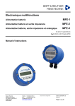
Vortex Flow Meter “trikon “ Manual We ask you to thoroughly read the manual and keep it safely. Subject to changes Version 1.11 METRA 10/2013 Vortex meter “trikon” Table of Contents 1. Safety Information..................................................................................................................................... 4 1.1 Range of Application ........................................................................................................................... 4 1.2 Hazards ............................................................................................................................................... 4 1.3 Safety .................................................................................................................................................. 4 1.4 Staff for Installation, Commissioning Work and Operation ................................................................. 4 1.4.1 Factory Settings ......................................................................................................................... 4 1.5 Repairs and Hazardous Materials....................................................................................................... 5 1.6 Right of Alterations .............................................................................................................................. 5 2. Description ................................................................................................................................................ 6 2.1 Measuring Principle............................................................................................................................. 6 2.2 System Structure................................................................................................................................. 6 2.3 Measured Quantity .............................................................................................................................. 7 2.4 Measuring Range ................................................................................................................................ 7 3. Installation ................................................................................................................................................. 7 3.1 General Information ............................................................................................................................ 7 3.2 Installation Information ........................................................................................................................ 7 3.3 Fitting the Sensor ................................................................................................................................ 8 3.3.1. Up- and Downstream Pipe Sections ........................................................................................ 8 3.3.1.1 Flow Straighteners ................................................................................................................. 9 3.3.2.1 Pressure and Temperature Compensation ........................................................................... 9 3.4 Turning the Electronics Housing / Turning the Up-Front Display ....................................................... 9 4. Electrical Connections ............................................................................................................................ 10 4.1 Connecting the “trikon” ...................................................................................................................... 10 4.2 Examples of Connections ................................................................................................................. 11 4.2.1 Application within Non-Explosion Hazard Areas .................................................................. 11 4.3 Load .................................................................................................................................................. 12 4.4 Max. Electrical Specifications Relevant to Safety in Accordance with the Declaration of Conformity ............................................................................................................................................... 13 ® 4.5 HART Connection ............................................................................................................................ 13 5. Configuration / Operation........................................................................................................................ 14 5.1 General ............................................................................................................................................. 14 5.2 Configuring Using the Keys on the Operating Unit ........................................................................... 14 5.2.1 Operation................................................................................................................................... 14 5.2.2 Up Front Display ....................................................................................................................... 15 5.2.3 Access Levels ........................................................................................................................... 15 5.2.4 Examples ................................................................................................................................... 16 5.2.4 Channel Overview .................................................................................................................... 18 Process ........................................................................................................................................................ 18 Special ......................................................................................................................................................... 18 Function Switches ............................................................................................................................ 19 5.3 Description of Functions ................................................................................................................... 20 5.3.1 Analog Operation (Channel 16)............................................................................................... 20 5.3.1.1 Output Signal Proportional to Upper Range Value .............................................................. 20 5.3.1.2 Output Signal Proportional to Measuring Range Span ....................................................... 20 5.3.1.3 Damping of Output Current (Channel 14)............................................................................ 20 5.3.1.4 Current Simulation (Channel 15) ......................................................................................... 21 5.4.1 Pulse Operation (Counter operation) ..................................................................................... 21 5.4.1.1 Two-Wire Current Pulse Output (Channel 16)..................................................................... 21 5.4.1.2 Two-Wire Current Pulse Output with HART Function ......................................................... 21 5.4.1.3 NAMUR – Pulses ................................................................................................................. 22 5.4.1.4 Pulse Value Factor (Channel 9)........................................................................................... 22 5.4.1.5 Pulse Width .......................................................................................................................... 23 5.4.1.6 Pulse Simulation .................................................................................................................. 23 5.5.1 Low-Flow Cutoff ....................................................................................................................... 24 5.6 Unit Selection (Channel 10) ........................................................................................................ 24 5.6.1 Standard Units .......................................................................................................................... 24 5.6.2 Special Units ............................................................................................................................. 24 5.6.2.1 Flow Rate Factor (Channel 29)............................................................................................ 25 5.6.2.2 Volume Factor (Channel 30)................................................................................................ 26 5.6.2.3 Pulse Ratio Factor (Channel 31) ......................................................................................... 26 Page 2 of 40 METRA Energie- Messtechnik GmbH Vortex meter “trikon” 5.7.1 Device Data (Channel 8) ...........................................................................................................27 5.8.1 Nominal Size (Channel 11) .......................................................................................................27 5.9.1 Medium (Channel 12) ................................................................................................................27 5.10.1 Density (Channel 13)...............................................................................................................27 5.11.1 Amplifier Limiter (Channel 22) ...............................................................................................28 5.12.1 Sensor Comparing Function (Channel 34) ...........................................................................28 5.13.1 Status Information (Channel 17) ............................................................................................28 6. Dimensions and Weights .........................................................................................................................29 6.1 Dimensions of the Various Models ....................................................................................................29 6.1.1 Types/Dimensions ...................................................................................................................29 6.1.2 Weight .....................................................................................................................................30 7. Specifications ..........................................................................................................................................31 7.1 Material ..............................................................................................................................................31 7.2 Process Connection ...........................................................................................................................31 7.3 Environmental Conditions ..................................................................................................................31 7.3.1 Ambient Temperature ...............................................................................................................31 7.3.2 Storage Temperature ................................................................................................................31 7.3.3 Climatic Category......................................................................................................................31 7.3.4 Degree of Protection .................................................................................................................31 7.3.5 Electromagnetic Compatibility ................................................................................................31 7.4 Process Conditions ............................................................................................................................32 7.4.1 Media Temperature ...................................................................................................................32 7.4.2 State of Aggregation .................................................................................................................32 7.4.3 Viscosity ....................................................................................................................................32 7.4.4 Media Pressure Limit ................................................................................................................33 7.4.5 Flow Rate Limit..........................................................................................................................33 7.4.6 Pressure Loss ...........................................................................................................................33 7.4.7 Cavitation in Liquids .................................................................................................................34 7.5 Characteristic Values .........................................................................................................................34 7.5.1 Reference Conditions ...............................................................................................................34 7.5.2 Measured Error (Accuracy) ......................................................................................................34 7.5.3 Repeatability ..............................................................................................................................34 7.6 Certificates Approvals and Standards ...............................................................................................34 8. “trikon” Configuration Data Sheet ............................................................................................................35 9. Approximate Calculation for Determining the Density of Gas and Superheated Steam.........................36 10. Tables ....................................................................................................................................................37 11. Certificate of Non-Objection for Contractor ...........................................................................................39 12. Index ......................................................................................................................................................40 METRA Energie-Messtechnik GmbH Page 3 of 40 Vortex meter “trikon” 1. Safety Information 1.1 Range of Application The vortex meter is used for rate-of-flow and volume measurement of liquids, gases and steam. Vortex meters of the “trikon” series are available in the nominal sizes ranging from 15 mm to 300 mm. Depending on the nominal size, they can be used from PN 10 to PN 40. The maximum permissible operating temperature for the medium is 260°C (450 °C for custom units). 1.2 Hazards The “trikon” vortex meter has been built in accordance with the latest safety standards. It has been tested and has left our factory in a safety-wise perfect condition. In the case of improper use or when not used as intended by design, hazardous situations can occur. For this reason note especially the warnings given in the operating instructions. 1.3 Safety The “trikon” vortex meter complies with the following safety criteria: • Safety requirements in accordance with EN 61010 • EMC requirements in accordance with EN 50081 Part 1 and 2; EN 50082 Part 1 and 2 • NAMUR recommendation NE 21 • System of protection for housing IP 67 in accordance with EN 60529 In the event of a power failure, the parameter data is saved in an EEPROM. 1.4 Staff for Installation, Commissioning Work and Operation • Only trained experts authorised by the operator of the system may run the installation work, electrical installation work, commissioning work, maintenance work and operate the system. Such staff must have read, understood and follow the information given in the operating instructions. • In the case of aggressive media, the resistance of all parts (seals, sensors, casings etc.) in contact with the medium must be clarified first. • As a rule, the rulings and regulations which apply in your country must be observed. 1.4.1 Factory Settings The vortex meters are set up in the factory in accordance with the operating conditions specified in your order. These settings are stated in the enclosed configuration data sheet. When making any changes to the factory settings, you must take note of Chapter 5 “Configuration / Operation”. Page 4 of 40 METRA Energie- Messtechnik GmbH Vortex meter “trikon” 1.5 Repairs and Hazardous Materials The following measures must be taken before you send your vortex meter back to METRA for repair: • • • In any case include with the equipment a note with a description of the failure, the application and the chemical and physical properties of the measured medium (for a form, see 14.2). The returned equipment has to be clean and dry; remove all residual liquid. Carefully inspect all lining grooves and slots where residual liquid might be found. This is especially important if the medium is detrimental to health (e.g. corrosive, poisonous, carcinogenic or radioactive etc.). We must ask you not to return any device about which you are not sure that it is absolutely safe. Costs that are caused by the possible disposal of the device or personal injuries (e.g. burns), because the unit has not been cleaned carefully, will be borne by the plant operator. If your vortex meter does not function properly, please contact our customer service: METRA Energie-Messtechnik GmbH Am Neuen Rheinhafen 4 67346 Speyer Tel.: +49 (6232) 657 – 519 Fax: +49 (6232) 657 – 200 1.6 Right of Alterations METRA Energie-Messtechnik GmbH reserves the right of introducing engineering changes due to improvements without having to provide separate information. METRA Energie-Messtechnik GmbH Page 5 of 40 Vortex meter “trikon” 2. Description The “trikon” vortex meter uses a new state-of-the art electronic converter. The “trikon” can display counter contents, flows, current output (4-20 mA) or vortex frequency. The flow rate is also indicated with an analog 4-20 mA current loop (according to NAMUR NE 21). The VTX 2 vortex meter is based on two-wire technology and supplied with power via this current loop. With the integrated HART Interface, longdistance data transmission to a control room or a portable on-site data terminal can be carried out via the same current loop. All the relevant operating or configuration data can be read from or written into the transmitter. Thus the operational mode of the vortex meter can be optimised for the measurement task on site or through a control system. 2.1 Measuring Principle When a liquid or gaseous with a certain minimum flow velocity meets an obstructive body, the liquid can only follow the contour of this body up to a particular point before it curls up to form a vortex. This happens alternately on either side of the body. The vortices travel downstream forming the “Kármán vortex trail”. The frequency of the forming vortices is proportional to the velocity of the flow. The series “trikon” vortex meter is equipped with a trapezoidal bluff body with a spring plate, which induces a precise and highly repeatable separation of the vortices for both liquid, gaseous media as well as steam. Both the dimensions of the bluff body and its specially defined separation edge (contour) guarantee a good linearity of the error curve. The vortices separating from the bluff body generate a vortex frequency, thus causing both velocity and pressure alterations, which are detected by a piezoelectric sensor and converted to output signals (4-20 mA or pulses). The conversion is performed by an electronic converter with both auto-adaptive and microprocessor-controlled filtering of the sensor signal. 1 Measuring pipe 2 Bluff body 3 Flowing medium 4 Vortex trail Fig. 1 Principle “Kármán vortex trail” 2.2 System Structure The vortex meter consists of three basic components: • • • The measurement pipe with the bluff body for producing the “Kármán vortex trail”. The sensor for detection the fluctuating pressure caused by the vortices. Electronic converter: The electronic converter pre-processes and evaluates the meter pulses. An analog 4-20 mA current loop and a digital communication module with HART protocol are standard features of the device. In addition, a pulse output according to NAMUR (scaled or unscaled) is available. The electronic converter is installed in an industrial-type housing with a screw-down cover. This ensures a high degree of protection against electromagnetic interference and moisture. The electronics is separated from the connection compartment. Page 6 of 40 METRA Energie- Messtechnik GmbH Vortex meter “trikon” 2.3 Measured Quantity The vortex meter measures the volume resp. the volumetric flow The mean velocity of the flow and the volumetric flow are proportional to the frequency of the vortices produced. 2.4 Measuring Range Nominal width DN Gases / Steam 3 in m /h K factor Liquid 3 in m /h (volume for air) DN 15 25 40 50 80 100 150 200 250 300 ANSI ½“ 1“ 1½“ 2“ 3“ 4“ 6“ 8“ 10“ 12“ 2 5 10 15 40 60 130 250 400 500 25 130 330 560 1600 2300 5300 9400 16000 20000 min 0.4 1 2.5 4 6 10 20 40 80 120 max 8 20 50 80 180 300 600 1200 1800 2500 Imp/l 277 57.7 15.3 7.63 2.22 Imp/m³ 1010 311 138 73 42 Table 1: Measurement ranges; the starting values for gas / steam refer to air (20°C, 1.013 bar) and those for liquids to water (20°C). 3. Installation 3.1 General Information • • • • • • • METRA vortex meters are precision flow meters. Inlet and outlet are covered with caps for protection against foreign bodies. Remove caps shortly before putting the device into operation. Observe the operating data on the vortex meter, in the order confirmation and the configuration data sheet. If you want to operate the device with different operating data, you must consult Bopp & Reuther Messtechnik GmbH indicating the factory number. The vortex meter may be mounted in any position. The vortex meter can be installed in horizontal or vertical pipes. The permissible ambient temperature (air temperature around the meter body) must not be exceeded. With both high liquid temperatures (e.g. steam) and a horizontal mounting position, it is recommended installing the vortex meter such that the position of the extension pipe with the electronics housing is either up or beside the pipe. Optimal is an installation with a slope of 30-45 °. If pipe and meter are thermally insulated, at least half of the extension pipe should be uninsulated. 3.2 Installation Information Warning • • • • • • Before mounting and commissioning the device, carefully read the Operating Instructions and the Declaration of Conformity. Before mounting or disassembling the device, depressurize and cool down the system. The measuring chamber of the vortex meter must be installed in the pipe in such a way that the IP 67 degree of protection according to IEC 529 is ensured. Technical information of the manufacturer referring to the use of the vortex meter in connection with corrosive liquids must be observed. The measuring chamber of the vortex meter must be included in the equipotential bonding of the pipe. The housing of the vortex meter which accommodates the electronics must not be exposed to sudden temperature changes. METRA Energie-Messtechnik GmbH Page 7 of 40 Vortex meter “trikon” 3.3 Fitting the Sensor • • • • • • • • • • • Clean the pipe of foreign bodies before installing the vortex meter. When flushing and purging the pipe, replace the vortex meter with a fitting part. Do not remove the caps on the in- and outlet of the vortex meter until you install the device. Ingress of foreign objects must be avoided. Observe the arrow on the meter body indicating flow direction. Mechanical loads exerted from the pipe onto the meter are not permitted. Ensure that the meter body is correctly centered and the gaskets do not project into the free pipe section. Centering rings or pipes can be helpful (supplied on request). The flat gaskets (not included) must be suitable for the liquid, the maximum operating temperature and the maximum pressure (it is recommended that groove gaskets with a layer and a centering ring be used). The inside diameter of the flat gasket must not be smaller than the inside diameter of the meter body. The screw bolts (not included) must comply with the specifications according to the operating conditions (flange type, pressure class). Long pipes, which are prone to vibration, must be supported or fixed in the up- and downstream pipe section. Carefully check the system for tightness after completing the installation. 3.3.1. Up- and Downstream Pipe Sections A fully present, turbulent and undisturbed velocity profile in the upstream pipe section is a prerequisite for a valid measurement. The minimum lengths are the following: 10 x nominal size for the upstream pipe section 5 x nominal size for the downstream pipe section In view of the most commonly encountered installation mistakes, following drawings show the minimum upstream and downstream pipe sections which are required: Upstream Downstream Reducer Upstream Downstream 2x 90 deg. bends in one plane Extension 2x 90 deg. bends in two different planes 90 deg. bend Valve fully open Fig. 2 Upstream and downstream pipe sections Page 8 of 40 METRA Energie- Messtechnik GmbH Vortex meter “trikon” 3.3.1.1 Flow Straighteners The installation of flow straighteners may reduce the influence of disturbances and the length of the required upstream pipe section. If the measurement has to be very precise, the upstream pipe section with a built-in flow straightener must be taken into account in the calibration process. 3.3.2.1 Pressure and Temperature Compensation If pressure and/or temperature measurements are planned, the respective measurement device must be installed in the downstream pipe section. The pressure measurement device must be installed 3 x nominal size and the temperature measurement device 5 x nominal size downstream from the vortex meter. 3.4 Turning the Electronics Housing / Turning the Up-Front Display At the transition from the sensor housing to the spacing pipe, the set screw with the 2 mm hex. socket must be loosened. Then the housing may be turned to the desired position. Finally the set screw is arrested once more. Stop Threaded pin m3 x m3 V: P Q: 12345678 m 3/h x m 3 /h P V: Q: 12345678 Fig. 3 Turning the electronics housing Screw M3 Schraube M3 Fig. 4 Up-front display / turning the display The up-front display may be turned in 90 degree increments. For this: 1. Unscrew the dial plate (loosen two M3 screws) 2. Turn the two size 5 hex. studs out 3. Now the operating unit with the display may be carefully pulled out of the connector and inserted again in the desired 90 degree position. 4. Fit the hex. studs and the dial plate once more. METRA Energie-Messtechnik GmbH Page 9 of 40 Vortex meter “trikon” 4. Electrical Connections The electrical connections are located behind the cover on the short side of the housing. To operate the “trikon”, a two-wire link (terminals 1+2) will do. This two-wire link has three functions: • • • Transmission of the 4-20 mA analog signal corresponding to the flow and the pre-set range limits. Provision of the auxiliary energy for the “trikon”. Transmission of the digital HART communication signal. In addition two further terminals (terminals 3 and 4) are available for the pulse output in accordance with NAMUR. Located on the connection pcb. are three tabs (TP) for servicing. I. Connection at TP 1-2 Voltage measurement 40-200mV corresponding to 4-20mA to check the analog signal II. Connection at TP 2-3 Communication via HART handheld terminal or HART interface (note explosion hazard regulations!) Vortex meter “trikon” Transmitter power supply unit 15 ... 30 V Caution For HART communication a minimum load of 250Ω is required! Pulse output Namur unscaled max. 5000 Hz scaled max. 18 Hz Test current loop [V] Fig. 5 Connection options 4.1 Connecting the “trikon” Power supply The power supply voltage range is 14 - 30 V DC, and 30 V DC must not be exceeded. Cable fitting Cable diameter Terminals Wire cross section Wire cross section : : : : : M20 x 1.5 6 to 12 mm GKDS Ex 4 mm² rigid 2.5 mm² flexible In order to comply with the stringent EMC requirements, shielded connecting cables must be used. The shield must be connected at both sides. A requirement for this is an effective and trouble-free equipotential bonding within the system. Page 10 of 40 METRA Energie- Messtechnik GmbH Vortex meter “trikon” 4.2 Examples of Connections 4.2.1 Application within Non-Explosion Hazard Areas Local display without signal transmission “trikon“ Pulse Connect shield to cable fitting External ground Analogue transmission 4 ... 20 mA to indicator or chart recorder “trikon“ Pulse Indicator Connect shield to cable fitting External ground Analogue transmission 1 ... 5 V to indicator or chart recorder “trikon“ Indicator Pulse External ground Connect shield to cable fitting Pulse transmission 1 ... 5 V to counter or computer “trikon“ Counter or computer Pulse External ground METRA Energie-Messtechnik GmbH Connect shield to cable fitting Page 11 of 40 Vortex meter “trikon” 4.3 Load As to the permissible load, several parameters need to be considered. In order to ensure reliable HART communication, the limits for the minimum load of RL ≥ 250 Ω must be observed. Maximum Load: The maximum load depends on the power supply voltage. The following relationship applies: Maximaleload Bürde Maximum 1000 Load Bürde[Ohm] [Ohm] 800 600 400 RLmin for HART communication 200 0 14 16 18 20 22 24 26 28 30 Power supply voltage [V][V] Versorgungsspannung Fig. 6 Load For UB < 15.2V : R = (UB – 14V) / 0.004A For UB ≥ 15.2V: R = (UB –8.5V) / 0.022A The resistances are stated in Ω. Page 12 of 40 METRA Energie- Messtechnik GmbH Vortex meter “trikon” 4.4 Max. Electrical Specifications Relevant to Safety in Accordance with the Declaration of Conformity Two-wire power supply and signal circuit (4 –20 mA current loop), terminals 1/2 Voltage Current Power Ui = 30 V DC Ii = 110 mA Pi = 825 mW Effective internal capacitance Effective internal inductance Ci ≤ 11 nF Li ≤ 4 µH Two-wire signal circuit (NAMUR pulses) (frequency signal output acc. to NAMUR), terminals 3/4 Voltage Current Power Ui = 20 V DC Ii = 50 mA Pi = 160 mW Effective internal capacitance Effective internal inductance Ci ≤ 11 nF Li ≤ 4 µH 4.5 HART® Connection For HART communication there are different connection options. In any case it is required that the loop resistance remains below the values given in Chapter 4.3. The HART interface may be connected at pads TP 2 and TP3 in the compartment for the terminals with the cover removed. If the HART interface is to be used at a different point within the current loop, then it may be connected as shown in Fig. 5. In the example given in Fig. 1, the connections of the HART communicator may be replaced with those of the PC or Laptop. METRA Energie-Messtechnik GmbH Page 13 of 40 Vortex meter “trikon” 5. Configuration / Operation 5.1 General The following options are available for configuring the transmitter. 1. HART communication through PACTware 2. HART communication through a handheld terminal 3. Up front operation through the keys and display of the operating unit 5.2 Configuring Using the Keys on the Operating Unit 5.2.1 Operation The instrument can be operated up front through the four keys on the operating unit. For this the cover needs to be removed: The following functions have been assigned to the keys: „P“ „▲“ „▼“ „↵ ↵“ Programming Plus Minus Enter Switches the programming mode on, sets decimal point. Increment Decrement Selects the next digit, carries a value over Keys Fig. 7: Operating unit Page 14 of 40 METRA Energie- Messtechnik GmbH Vortex meter “trikon” 5.2.2 Up Front Display On the display all variables and parameter settings may be displayed. The process variables are marked by the position of the cursor, the parameters and service data by a two-digit channel number. When in the operating mode (roll mode) the flow and count are displayed in alternating fashion. By operating the plus or the minus key, the operator may switch over the display to indicate the desired channel. After about 5 minutes the selected channel changes back automatically to the roll mode where count and flow are displayed. Keeping the plus key depressed for 3 seconds will invoke the roll mode immediately. 5.2.3 Access Levels When operating the instrument via the keys, there are three access levels which must be considered. In channel “a” the desired access level can be enabled at digit 0 (see also table “Functions switches”). • • • Display level (operating mode) A/0 All configuration and measurement data can be displayed, writing can only be done through channel a. User level (programming mode) A/1 In addition the default settings for the vortex meter can be configured. On this level, operation of the function switches can be changed. Service level (programming mode) A/2 All coefficients and alignment parameters can be configured. METRA Energie-Messtechnik GmbH Page 15 of 40 Vortex meter “trikon” 5.2.4 Examples General note: After each change to the settings the instrument should be reset (power on reset or reset through function switch B2) so as to check the newly entered resp. changed values through invoking the corresponding channel number. Plus key (▲) To select a channel and to change the content of the channel – in the positive direction. Example: Increase for channel 6 from 1 to 2. Minus key (▼) To select a channel and to change the content of the channel – in the negative direction. Example: Decrease for channel 6 from 2 to 1. Programming key (P) This key has two functions: - Change of channel content The desired channel is selected through the plus or the minus key. Operating the programming key enables the channel so that its content may be changed. The cursor will be displayed. Example: If channel 11 (nominal width) has been selected, then the cursor will appear at position 2. - Setting the position for the decimal point. If the desired channel has been selected and if the programming key has been operated so that the cursor is visible, now a decimal point may be set at the position of the cursor. Pressing the programming key once more deletes the decimal point. Example: Here in channel 6 a decimal point is set at position 4. For the following channels floating point entries are provided for: - Max. flow - Min. flow - k factor - Pulse factor - Operating density Page 16 of 40 = = = = = Channel No. 6 Channel No. 7 Channel No. 8 Channel No. 9 Channel No. 13 METRA Energie- Messtechnik GmbH Vortex meter “trikon” Enter key (↵ ↵) To move the entry position (the cursor moves from left to right) and for taking over the current value (cursor is no longer displayed) Moreover, with the enter key it is possible to reset the status information in channel 17. Example: In order to activate channel 6, the enter key needs to be operated four times so that the cursor moves from position 4 to the right. Pressing the enter key once more will shift the cursor out of the display to the right and channel 6 with the current content (1.0000) is activated. METRA Energie-Messtechnik GmbH Page 17 of 40 Vortex meter “trikon” 5.2.4 Channel Overview Channel Code Table Channel Function Default Service values Special settings Basic settings Process variables Digits (0) (1) (2) (3) (4) (5) 6 7 8 9 10 11 12 13 14 15 16 17 a b c d 20 21 22 23 24 25 26 27 28 29 30 31 32 33 34 35 36 37 38 39 40 41 Total totalizer Flow rate Percentage display Current display Vortex frequency Resettable counter Upper range value Lower range value k factor Pulse value factor Unit selection Nominal size Medium Minimum operating density Current damping Current simulation 2-wire current loop Status information Function switch a Function switch b Function switch c Function switch d Capacitance selection Resistance selection Amplifier level Intermediate filter fu Intermediate filter fo Output filter fu Output filter fo Lower switching voltage Upper switching voltage Flow rate factor Volume factor Pulse ratio factor Current calibration 4mA Current calibration 20mA Sensor comparator Quartz frequency Amplitude RQ Amplitude LQ PZF 2 Signal amplitude PEF --- Flow velocity Page 18 of 40 8 8 4 4 8 8 5 5 5 3 2 3 1 5 3 3 1 3 7 7 7 7 1 2 1 1 1 2 2 3 3 5 5 5 5 5 3 5 3 3 3 3 3 4 Value Order of entries Keys Unit V1 Q Q/Qmax I f V2 Qmax Qmin K 1 (5) DN Liquid/gas/steam ρ 3 4.0 Analog/pulses 000 0001110 0010010 0000000 0141100 0-5 0-15 4 0-3 0-3 0-15 0-15 0.70 3.30 1 1 1 400 14000 127 460.00 approx. 2.5 approx. 2.5 0-5 0-5 v m³ m³/h % mA Hz m³ m³/h m³/h Imp/l o. Imp/m³ m³/h (mm) kg/m³ s mA V V kHz V V V V V m/s 3 1 2 METRA Energie- Messtechnik GmbH Level a/o 1 1 1 1 1 1 1 1 1 1 1 0 1 1 1 2 2 2 2 2 2 2 2 2 2 2 2 Y Y Y Y - Vortex meter “trikon” Function Switches Position Channel (switch) 0 a b c Access levels Failure signal (Alarm at 21.8mA) 0: Display level 1: User level 2: Service level 0: OFF 1: ON Auto-adaptation (cap. selection) Auto-adaptation (filter selection) Filter bandwidth 0: OFF 1: ON 0: OFF 1: ON 0: 20dB (normal) 1: 40dB Amplifier guidance (in stages K22) Hardware reset Amplifier bandwidth at Qmax 0: OFF 1: ON 0: OFF 1: ON 0: normal 1: wide Filter guidance (Output filter fo) Open measurement range 0: OFF 1: ON 0: OFF 1: ON 0: OFF (for HART comm.) 1: ON LCD test Filter guidance (Output filter fu) Auto-adaptation (Selection of the number of stages) 0: OFF 1: ON 0: OFF 1: ON Current simulation (value of K15) Quick start Current pulse output with HART comm. (only at 150ms) NAMUR output 0: OFF 1: ON 0: OFF 1: ON 0: OFF 1: ON 0: OFF 1: Original frequency 2: Scaled pulses 3-8: Simulation values * Pulse simulation (NAMUR output) Pule width select 0: OFF 1: ON 0: 150ms/3Hz 1: 100ms/5Hz 2: 45ms/11Hz 3: 28ms/18Hz Counter reset 0: OFF 1: Reset 0: Default 1 0: Default 2 3 0: OFF 1: ON Current pulse output (general.) 0: Default 0 to 6 Alignment PWM / Quarz 6 Low flow suppression 0: Default 4 5 d 0: OFF 1: ON * Simulation values NAMUR output METRA Energie-Messtechnik GmbH --- Frequency simulation 3: 4: 5: 6: 7: 28Hz 112.5Hz 900Hz 1800Hz 3600Hz Pulse simulation 8: Pulse width Page 19 of 40 Vortex meter “trikon” 5.3 Description of Functions 5.3.1 Analog Operation (Channel 16) The analog output signal of 4 to 20 mA can be freely assigned to the desired measuring range within the flow rate limits of the corresponding counter quantity. There are two analog operating modes: 5.3.1.1 Output Signal Proportional to Upper Range Value 4 mA = Q = 0 (Mode 0) Output signal [mA] 20 4 0 Measuring range 0 Q min (Channel 7) Q max Q Nom (Channel 6) Below Qmin (Channel 7) low-flow cutoff 5.3.1.2 Output Signal Proportional to Measuring Range Span 4 mA = Q min (Mode 3) Output signal [mA] 20 4 0 Measuring range 0 Q min (Channel 7) Q max Q Nom (Channel 6) This setting is made with Channel 16 Mode Operating mode 0 4 mA = Q = 0 3 4 mA = Q min 5.3.1.3 Damping of Output Current (Channel 14) With channel 14 you set the damping ratio. The setting range is between 1 (no damping) and 200 (highest degree of damping = time constant 200 s). Page 20 of 40 METRA Energie- Messtechnik GmbH Vortex meter “trikon” 5.3.1.4 Current Simulation (Channel 15) With the current simulation you can set different output currents between 4 and 22 mA. How to proceed: 1 2 3 Switch on current simulation with function switch A 5 (enter 1). Set the desired output current with Channel 15 (enter value in mA). Switch off current simulation with function switch A 5 (enter 0). 5.4.1 Pulse Operation (Counter operation) 5.4.1.1 Two-Wire Current Pulse Output (Channel 16) For volume measurements you can switch the two-wire circuit to pulse operation. Current pulses between 4 mA = low and 20 mA = high will be supplied as the output signal. You can select between a scalable pulse output or a pulse output of original vortex pulses. This setting is made with Channel 16: Mode Operating mode 1 Scaled pulses 2 Original vortex pulses In addition to this setting, the analog/digital jumper on the front of the electronics must be set to digital operation. Note! HART communication is not permitted during pulse operation. For HART configuration, the pulse output must be switched off temporarily (function switch D 3, enter 1). 5.4.1.2 Two-Wire Current Pulse Output with HART Function In the analog operating mode (Mode 0) a pulse output with simultaneous two-wire HART communication can be utilised. Pulse signal specs. Current pulses: Current Low ≤ 9 mA Current High ≥ 12 mA Pulse width 150 ms For this, the function switch (C5 is set to 1 [on]). The analog/digital jumper on the front of the electronics must be set to analog operation. The pulse width for the pulses which are output must be set to 150 ms. V: Q: m3 x m 3 /h 12345678 P A/D--Umschalter Switch A/D Ana log Digital Fig. 8 Analog-Digital Switch METRA Energie-Messtechnik GmbH Page 21 of 40 Vortex meter “trikon” 5.4.1.3 NAMUR – Pulses In addition to the 2-wire connection, a separate pulse output in accordance with NAMUR is available. The additional NAMUR output can either be set to original vortex pulses (e.g. for test purposes, if a high pulse resolution is necessary) or to scaled pulses with selectable meter factor and pulse width. This setting is made with function switch D 5: Setting Function 0 Pulses off 1 Original vortex pulses 2 Scaled pulses 5.4.1.4 Pulse Value Factor (Channel 9) Through the pulse value factor you can set the meter factor of the output pulses and the counter increment. You can set the following decadic steps for the pulse value factor (Channel 9): 0.01 0.1 1 10 100 Example: If the pulse value factor is 10 then the following applies a) for the pulse output: 1 pulse = 10 units (e.g. 10 m³), depending on the selected unit b) for the meter’s display (with pulse ratio factor 1, see Chapter 6.2.4): 1 counter increment = 10 units (e.g. 10 m³) If the pulse output is scaled, it must be ensured that the maximum frequency of the pulse output, depending on the selected pulse width, is not exceeded (see Table 5.6.1.5). The smallest permissible pulse value factor Z is given by Z≥ Q max f max Q max: max. flow rate [selected unit/seconds] f max: max. frequency of the scaled pulse output (depending on the selected pulse width, see Table 5.6.1.5) Example 1: Q max = 400 m³ / h = 0.111 m³ / s Pulse width 150 ms = f max = 3 Hz Z ≥ 0.111 / 3 = 0.037 m³ thus a smallest pulse value of Z = 0.1 can be selected, i.e. 1 pulse = 0.1 m³ Page 22 of 40 METRA Energie- Messtechnik GmbH Vortex meter “trikon” Example 2: Q max = 60,000 kg / h = 16.67 kg / sec Pulse width 28 ms = f max = 18 Hz Z ≥ 16.67 / 18 = 0.926 kg ⇒ smallest pulse value possible Z = 1 (or higher), i.e. 1 pulse = 1 kg 5.4.1.5 Pulse Width (Function switch D 6) The output pulse width can be selected according to the following table: Setting Pulse width Max. frequency 0 150 ms 3 Hz 1 100 ms 5 Hz 2 45 ms 11 Hz 3 28 ms 18 Hz 5.4.1.6 Pulse Simulation NAMUR pulse output With pulse simulation, various output pulses can be simulated. During a simulation, the transmission of the vortex signals is stopped. 1. Switch on pulse simulation with function switch C 6. 2. Select output pulses with D 5. Setting Value [Hz] 3 28 4 112,5 5 900 6 1800 7 3600 8 (pulse width according to D 6) 3 5 11 18 Two-wire current pulses Pulse simulation has an effect only on the scaled pulse output. Pulse width must be set to 150 ms (3Hz). METRA Energie-Messtechnik GmbH Page 23 of 40 Vortex meter “trikon” 5.5.1 Low-Flow Cutoff Below the programmed lower range value (Qmin), the output variable is set to zero (0) , i.e., the current output decreases to 4 mA for analog operation, and the pulse output is switched off for pulse operation. Low-flow cutoff can be deactivated for special applications (e.g. pulse output for test purposes). Set function switch D 2 to 0 (OFF). 5.6 Unit Selection (Channel 10) 5.6.1 Standard Units You can select the desired unit with Channel 10. Setting Unit 0 l/s 1 l/min Setting Unit 11 Impgal/h 2 l/h 12 gal/s 3 4 m³/s m³/min 13 gal/min 5 6 m³/h ft³/s 14 gal/h 7 8 ft³/min ft³/h 15 USER 9 Impgal/s 16 kg/h 10 Impgal/min 17 t/h 5.6.2 Special Units In order to activate this function, you must set channel 10 to the USER unit (15). With channel 29 or 30 you can set the factors with which the process values can be converted to any unit or display value. If the default setting is active, the conversion factors in channel 29 and 30 are set to 1, i.e., the value is displayed in the previously valid units (e.g. in m³ or m³/h). The value range of these factors is: 0.0001 ≤ F ≤ 99990. Caution: The counter must first be configured for the required operating volume measuring range with the units [m³/h]. The basic units (m³ or m³/h) are to be included for the calculation of the conversion factors to the desired display value. Note: The maximum flow rate must not exceed a number of 99990. Page 24 of 40 METRA Energie- Messtechnik GmbH Vortex meter “trikon” 5.6.2.1 Flow Rate Factor (Channel 29) With channel 29 you set the conversion factors for the flow rate display. Example 1: Converting standard volume flow rate for the unit [m³/h] Flow rate factor FD = ρB ρN ρ B: Operating density, e.g. ρ B = 7.00 kg/m³ ρ N: Standard density, e.g. ρ N = 1.28 kg/m³ FD = 7.00 = 5.4689 1.28 Example 2: Converting the standard volume flow rate for the unit [yard³ / d], for ρ B / ρ N = 6.0000 Flow rate factor FD = ρB x ⋅ ρN y x: Conversion factor for volume unit e.g. 1 m³ = 1.30795 yard³, i.e. x= 1.30795 y: Conversion factor for time unit e.g. 1 h = 1 / 24 d, i.e. y= 1 / 24 thus the flow rate factor is calculated FD = 6 ⋅ METRA Energie-Messtechnik GmbH 1.30795 = 188.34 1 24 Page 25 of 40 Vortex meter “trikon” 5.6.2.2 Volume Factor (Channel 30) With Channel 30 you set the conversion factors for volume measurement. Example 1: Conversion to standard volume for the unit [m³] Volume factor FV = FV = ρB ρN 7.00 = 5.4689 1.28 Example 2: Conversion to standard volume for the unit [yard³], where ρB / ρN = 6.000 Volume factor: FV = ρB ⋅x ρN FV = 6 x 1.30795 = 7.8477 x: Conversion factor for volume unit e.g. 1 m³ = 1.30795 yard³, d. h. x =1,30795 5.6.2.3 Pulse Ratio Factor (Channel 31) With the factor (FI) that can be set with Channel 31 the magnitude of counter increment (display) W zähl and pulse output (NAMUR and current pulses) W puls can be set differently. For the standard setting, the factor is 1, i.e. the significance of counter increment and pulse output are identical. W puls = FI • W zäh Example: FI = 10 Results in a transformation of the scaled pulse output to ten times as much as the counter increment, i.e., the pulse output is ten times faster. Caution: Observe the limit value for the maximum frequency of the pulse output (see Table 4.4). FI = 0.1 Results in a reduction of the scaled pulse output to one 10 of the counter increment, i.e., the pulse output is ten times slower. th The value range of this factor is: 0.0001 ≤ factor ≤ 99999 Page 26 of 40 METRA Energie- Messtechnik GmbH Vortex meter “trikon” 5.7.1 Device Data (Channel 8) The k factor is a device constant that is calculated for each device through a factory calibration. The value is entered in [pulses/l] for DN 15 to DN 80 in [pulses/m³] for DN 100 to DN 250 The measuring range table lists the mean values for the individual nominal size. 5.8.1 Nominal Size (Channel 11) When you exchange the electronics, the nominal size must be set as follows: Entry DN DIN In. 015 15 ½ 025 25 1 040 40 1½ 050 50 2 080 80 3 100 100 4 150 150 6 200 200 8 250 250 10 5.9.1 Medium (Channel 12) The medium determines the limit values of the measuring range (see measuring range table) and the automatic gain and filter settings of the electronics. The setting is made in three classes. Setting Medium 0 Gas 1 Liquid 2 Steam 5.10.1 Density (Channel 13) Here you must enter the (minimum) operating density of the medium. With this density, apart from the effect on the automatic amplifier and filter setting, the conversion is performed with respect to the standard mass unit that may have been selected. The operating density must be entered in the unit [kg/m³]. METRA Energie-Messtechnik GmbH Page 27 of 40 Vortex meter “trikon” 5.11.1 Amplifier Limiter (Channel 22) The optimum settings for the intended operating conditions are factory-preset. However, periodic pulsations or vibrations of the pipe may generate unwanted signals, and a flow rate is displayed in spite of the fact that the flow rate is zero. With the setting in Channel 22 you can limit the amplifier gain in selectable levels. Thus the device can be adjusted to the corresponding operating conditions. A lower gain stage means lower gain. In this way the sensitivity to disturbances can be reduced when the flow rate is zero. Stage Gain factor 0 1 1 2 2 4 3 8 4 16 5 32 6 64 Caution: If the stage number is too low, the measuring range may be restricted at low flow rates. During operation the currently active gains stage is displayed, not the limit. 5.12.1 Sensor Comparing Function (Channel 34) This function contains a calibration value for suppressing inferences. It serves the purposes of symmetry alignment between the two sensor circuits. When changing the preamplifier stage, the sensor comparing function should also be aligned. 5.13.1 Status Information (Channel 17) Channel 17 displays the current status of the device. If a fault is detected, it will be displayed in the status channel. You clear the fault by acknowledging it by shifting. If the same message is displayed again, it is valid. Code no. 001 002 003 004 005 006 Meaning Changing the operating data after automatic setting Performing settings manually Flow rate below Qmin Flow rate is in low-flow operation (90 to 100%) Incorrect filter No valid data in the EEPROM 010 011 ↓ 046 Incorrect data in Channel 0 Incorrect data in Channel 1 ↓ Incorrect data in Channel 35 050 051 Data entry via interface does not function properly Incorrect measuring range 060 Incorrect unit of measurement 100 Storage error (alarm 21.8 mA) Page 28 of 40 METRA Energie- Messtechnik GmbH Vortex meter “trikon” 6. Dimensions and Weights 6.1 Dimensions of the Various Models 6.1.1 Types/Dimensions DN DIN 15 25 40 50 80 100 150 200 250 300 DA [mm] Inches ½“ 1“ 1½“ 2“ 3“ 4“ 6“ 8“ 1 0“ 12“ Pressure rating: PN 40 / Class 300 Di H [mm] [mm] 45 67 85 105 136 164 220 275 330 380 16 27 41,5 53 80 103 154 202 253 303 335 335 340 340 350 365 400 430 460 500 LS [mm] Sandwich 65 65 65 65 65 65 90 120 140 160 LF [mm] Flange 200 200 200 200 200 250 300 300 380 450 Other nominal widths upon request. Flange model METRA Energie-Messtechnik GmbH Sandwich model Page 29 of 40 Vortex meter “trikon” 6.1.2 Weight DN DIN 15 25 40 50 80 100 150 200 250 300 ANSI ½" 1" 1 1/2" 2" 3" 4" 6" 8" 10" 12" Page 30 of 40 Weight sandwich model [kg] 2.0 2.5 3.0 3.5 9.5 12.5 20.5 30.5 40.5 Weight flange model [kg] 4.5 7 10 12 26 38 METRA Energie- Messtechnik GmbH Vortex meter “trikon” 7. Specifications 7.1 Material Sensor: stainless steel 1.4571 and 3.1B certificate Housing with bluff body: stainless steel 1.4404 and 3.1B certificate Seals: viton and graphite (other materials upon request) Electronics housing: die-cast aluminum 7.2 Process Connection Sandwich: Flange: DN 15 to DN 300 and PN 10 to PN 40 (PN 100 upon request) ½“ – 12“ Class 150 and Class 300 (Class 600 upon request) DN 15 to DN 300 and PN 10 to PN 40 (PN 100 upon request) ½“ – 12“ Class 150 and Class 300 (Class 600 upon request) Larger nominal sizes and pressure stages upon request. 7.3 Environmental Conditions Exposure of the electronics housing to sudden temperature changes must be avoided. 7.3.1 Ambient Temperature -40° C to +70° C Operation of the LC display is only ensured down to -10° C. 7.3.2 Storage Temperature -40° C to +70° C 7.3.3 Climatic Category Class D IEC 654-1 7.3.4 Degree of Protection IP67 IEC 529 / EN 60529 7.3.5 Electromagnetic Compatibility According to EMC guidelines 89/336/EWG, EN 50081 Part 1 and 2; EN 50082 Part 1 and 2 as well as NAMUR NE 21 Electromagnetic compatibility is only ensured when the electronics housing is closed. When the electronics housing is open, the device may malfunction due to electromagnetic signal pickup (see Chapter 4.2 Connecting the “trikon”). METRA Energie-Messtechnik GmbH Page 31 of 40 Vortex meter “trikon” 7.4 Process Conditions 7.4.1 Media Temperature -40°C to 260°C standard up to 450°C for custom versions The temperature categories for category II media are given in the following table: Temperature category Media temperature Ambient temperature range (electronics housing) T1 up to +450 °C -40 °C < Ta < + 70 °C T2 up to +300 °C -40 °C < Ta < + 70 °C T3 up to +200 °C -40 °C < Ta < + 70 °C T4 up to +135 °C -40 °C < Ta < + 70 °C T5 up to +100 °C -40 °C < Ta < + 70 °C T6 up to +85 °C -40 °C < Ta < + 70 °C The temperature categories for category I/II media are given in the following table: Temperature category Media temperature Ambient temperature range (electronics housing) T4 -20 °C to +60 °C -40 °C < Ta < + 70 °C T5 -20 °C to +60 °C -40 °C < Ta < + 70 °C T6 -20 °C to +60 °C -40 °C < Ta < + 70 °C The process pressure for the media must, in the case of category I media, range between 0.8 bar and 1.1 bar. 7.4.2 State of Aggregation Liquids, gases, and steam 7.4.3 Viscosity Viscosity limits the linear measuring range for which the error limits (measured error) are valid. Linearity limit QLin = 2.826 ⋅ D ⋅ Re⋅ν D = inside diameter [mm] Re = Reynolds Number (limit value) ν = dynamic viscosity [m²/s] Page 32 of 40 METRA Energie- Messtechnik GmbH Vortex meter “trikon” 7.4.4 Media Pressure Limit Depends on the design. 7.4.5 Flow Rate Limit The max. velocity for gases and steam is about 80 m/s, and for liquids about 10 m/s. In the case of liquids the cavitation limit needs to be observed in addition. For gases having a density < 1.2kg/m³ the lower limit for the measurements can be calculated from Qmin = 1.1 QL ρB QL = lower flow limit for air [m³/h] (see Table 2.4) The limit for linearity will depend on viscosity and is for a Reynolds number of Re=20000 (see 7.4.3). This can be checked using the following equation: QLin = 2.826 ⋅ D ⋅ Re⋅ν 7.4.6 Pressure Loss Pressure loss can be calculated using the following equation: ∆p = 1400 ⋅ ρ B ⋅ where ρB QB DN = = = QB2 [mbar] DN 4 3 Operating density [kg/m ] 3 Operating flow rate [m /h] Nominal size [mm]. The results obtained will represent a rough estimate. Example: 3 DN 100 ; QB = 230 m /h ; ρB = 7.1 kg/m (saturated steam at 14 bar) 2 3 4 ∆p = 1400 x 7,1 x 230 /100 = 5,25 mbar Remark: see Annex − Table for saturated steam − Approximate calculation for determining operating density − Gas constants (Ri table) METRA Energie-Messtechnik GmbH Page 33 of 40 Vortex meter “trikon” 7.4.7 Cavitation in Liquids When running measurements on liquids, the effect of cavitation within the vortex meter must be avoided. For this it must be ensured by design that the pressure downstream of the vortex meter can not drop below the vapour pressure for the liquid used. At an approximate back pressure given below, cavitation can be avoided. pmin ≥ 2.8 x ∆p + 1.3 x pv where Example: pmin ∆p = = pv = Minimum pressure in the pipe Pressure loss 2 4 ∆p = 1400 x ρB x (QB / DN ) Vapour pressure of the liquid being measured under operating conditions 3 DN 80; water of 20°C ; → Q = 108 m /h 2 4 ∆pVTX 2 = 1400 x 998.3 x (108 / 80 ) → ∆p VTX 2 = 398 mbar pv = 0.02337 bar (from VDO table for water vapour) ⇒ pmin ≥ 2.8 x 0.40 + 1.3 x 0.02337 = 1.15 bar Thus for a VTX 2 DN 80 (water, 20°C, QB = 108 m³/h) a pressure over 1.15 bar is required so as to avoid cavitation. Remark: see table in the Annex: density and vapour pressure of water. 7.5 Characteristic Values 7.5.1 Reference Conditions According to IEC 770: 20°C, 65% relative humidity, 101.3 kPa 7.5.2 Measured Error (Accuracy) Gas/steam Liquids Re ≥ 20,000 ±1.0% of measured value ±1.0% of measured value 10,000 < Re ≤ 20,000 ± 1.0 % of upper value (for Re = 20,000) ± 1.0 % of upper value (for Re = 20,000) 7.5.3 Repeatability ± 0.15 % of measured value 7.6 Certificates Approvals and Standards CE mark EMC in accordance with directive 89/336/EWG, EN 50081 Part 1 and 2; EN 50082 Part 1 and 2, as well as NAMUR NE 21 Type of protection for the housing: EN 60529 NAMUR: EN 60947-5-6 Equipment safety: EN 61010 Pressurised equipment directive: 97/23/EG Page 34 of 40 METRA Energie- Messtechnik GmbH Vortex meter “trikon” 8. “trikon” Configuration Data Sheet Channel Denomination Setting No. Customer Order no. Serial no. Tag no. (meas. point no.) Type (model code) Nominal flow rate Liquid Nominal pressure 6 Upper range value 7 Lower range value m³/h Gas Qmax □ Qmin □ m³/h □ m³/h □ up to DN 80 from DN 100 8 k factor 9 Pulse value factor Z □ 0.01 Meter factor 1 pulse ≘ 10 11 m³/h pulses/l □ 0.1 pulses/m³ □ 1 □ 10 □ 100 1 counter increment ≘ □0 □1 □2 □3 □4 □5 l/s l/min l/h m³/s m³/min m³/h □6 □7 ft³/s □8 ft³/min ft³/h □9 Impgal/s Units Nominal size DN □10 □11 □12 □13 □14 Impgal/min Impgal/h gal/s gal/min gal/h □ 015 □ 025 □ 040 □ 050 □ 080 □ 100 □15 □16 □17 USER kg/h □ 150 □ 200 t/h □ 250 □ 300 □ DIN 15 25 40 50 80 100 150 200 250 300 □ In. ½“ 1“ 1½“ 2“ 3“ 4“ 6“ 8“ 10" 12" 12 Medium 13 14 Operating density Damping 16 2-wire current loop 29 Flow rate factor FD □1 □ . 30 Volume factor FV □1 □ . 31 Pulse ratio factor FJ □1 □ . D5 NAMUR pulse output D5 Pulse width □ 0 Gas ρmin = □ (from 1 to 200) □ 0 4mA = 0 □ 0 OFF □ 0 150ms/3Hz □ 1 Liquid □ 2 Steam kg/m³ □ 3 4mA = Qmin □ 2 Original vortex pulses □ 1 Original vortex frequ. □ 1 100ms/5Hz □ 1 Scaled pulses □ 2 Scaled pulses □ 2 45ms/11Hz □ 3 28ms/18Hz E-series no./date METRA Energie-Messtechnik GmbH Page 35 of 40 Vortex meter “trikon” 9. Approximate Calculation for Determining the Density of Gas and Superheated Steam ρ = p / (Ri x T) [kg/m³] where ρ p Ri T = = = = Operating density Operating pressure (abs.) Specific gas constant Operating temperature Example: Medium air; 5 bar; t = 20°C [kg/m³] [N/m²] resp. [Pa] [Nm/kgK] [K] 5 ρ = (5 x 10 ) / (260 x 293.15) ρ = 6.56 kg/m³ Specific gas constant Ri Type of gas Argon (Ar) Acetylene (C2H2) Ammonia (NH3) Helium (He) Carbondioxide (CO2) Carbonmonoxide (CO) Air Methane (CH4) Oxygen (O2) Nitrogen (N2) Water vapour (H2O) Hydrogen (H2) Ri in [Nm/(kg x K)] 208 320 488 2078 189 297 287 519 260 297 462 4158 Table 12: Specific gas constants of some gases Page 36 of 40 METRA Energie- Messtechnik GmbH Vortex meter “trikon” 10. Tables State quantities of water and steam Pressure (abs.) Boiling temperature Steam density p [bar] ts [°C] ρs [kg/m³] 0.30 0.40 0.60 0.80 69.12 75.89 85.95 93.51 0.1912 0.2504 0.3660 0.4792 1.0 1.2 1.6 2.0 99.63 104.81 131.32 120.23 0.5905 0.7003 0.9167 1.130 3.0 3.4 4.0 4.5 133.54 137.86 143.63 147.92 1.652 1.858 2.164 2.417 5.0 6.0 7.0 8.0 151.85 158.84 164.06 170.41 2.669 3.170 3.667 4.161 9.0 10 11 12 175.36 179.88 184.06 187.96 4.654 5.114 5.634 6.123 13 14 15 16 191.60 195.04 198.28 201.37 6.612 7.100 7.580 8.077 17 18 19 20 204.30 207.11 209.79 212.37 8.566 9.056 9.546 10.04 22 26 30 34 217.24 226.03 233.84 240.88 11.02 13.00 15.00 17.02 38 40 247.31 250.33 19.07 20.11 METRA Energie-Messtechnik GmbH Page 37 of 40 Vortex meter “trikon” Density and vapour pressure of water T °C Pd bar ρ 3 kg/m T °C Pd bar ρ 3 kg/m T °C Pd bar ρ 3 kg/m 0 1 2 3 4 5 6 7 8 9 10 0.00611 0.00657 0.00706 0.00758 0.00813 0.00872 0.00935 0.01001 0.01072 0.01147 0.01227 999.8 999.9 999.9 999.9 1000 1000 1000 999.9 999.9 999.8 999.7 56 57 58 59 60 0.16511 0.17313 0.18147 0.19016 0.19920 985.2 984.6 984.2 983.7 983.2 999.7 999.6 999.4 999.3 999.2 999.0 998.8 998.7 998.5 998.3 982.6 982.1 981.6 981.1 980.5 979.9 979.3 978.8 978.2 977.7 941.2 939.6 937.9 936.2 934.6 932.8 931.1 929.4 927.6 925.8 0.01312 0.01401 0.01497 0.01597 0.01704 0.01817 0.01936 0.02062 0.02196 0.02337 0.2086 0.2184 0.2286 0.2391 0.2501 0.2615 0.2733 0.2856 0.2984 0.3116 2.1145 2.2504 2.3933 2.5435 2.7013 2.8670 3.041 3.223 3.414 3.614 11 12 13 14 15 16 17 18 19 20 61 62 63 64 65 66 67 68 69 70 122 124 126 128 130 132 134 136 138 140 998.1 997.8 997.6 997.4 997.1 996.8 996.6 996.3 996.0 995.7 977.0 976.5 976.0 975.3 974.8 974.1 973.5 972.9 972.3 971.6 921.4 916.8 912.1 907.3 902.4 897.3 892.1 886.9 881.5 876.0 870.4 864.7 0.02485 0.02642 0.02808 0.02982 0.03166 0.03360 0.03564 0.03778 0.04004 0.04241 0.3253 0.3396 0.3543 0.3696 0.3855 0.4019 0.4189 0.4365 0.4547 0.4736 4.155 4.760 5.433 6.181 7.008 7.920 8.924 10.027 11.233 12.551 13.987 15.55 21 22 23 24 25 26 27 28 29 30 71 72 73 74 75 76 77 78 79 80 145 150 155 160 165 170 175 180 185 190 195 200 995.4 995.1 994.7 994.4 994.0 993.7 993.3 993.0 992.7 992.3 971.0 970.4 969.7 969.1 968.4 967.8 967.1 966.5 965.8 965.2 858.8 852.8 846.7 840.3 833.9 827.3 820.5 813.6 806.5 799.2 0.04491 0.04753 0.05029 0.05318 0.05622 0.05940 0.06274 0.06624 0.06991 0.07375 0.4931 0.5133 0.5342 0.5557 0.5780 0.6011 0.6249 0.6495 0.6749 0.7011 17.243 19.077 21.060 23.198 25.501 27.976 30.632 33.478 36.523 39.776 31 32 33 34 35 36 37 38 39 40 81 82 83 84 85 86 87 88 89 90 205 210 215 220 225 230 235 240 245 250 991.9 991.5 991.1 990.7 990.2 989.8 989.4 988.9 988.4 988.0 964.4 963.8 963.0 962.4 961.6 961.0 960.2 959.6 958.6 958.1 791.6 783.9 775.9 767.8 759.3 750.5 741.5 732.1 722.3 712.2 0.07777 0.08198 0.08639 0.09100 0.09582 0.10086 0.10612 0.11162 0.11736 0.12335 0.7281 0.7561 0.7849 0.8146 0.8453 0.8769 0.9094 0.9430 0.9776 1.0133 43.246 46.943 50.877 55.058 59.496 64.202 69.186 74.461 80.037 85.927 41 42 43 44 45 46 47 48 49 50 91 92 93 94 95 96 97 98 99 100 255 260 265 270 275 280 285 290 295 300 987.6 987.1 986.6 986.2 985.7 956.7 955.2 953.7 952.2 950.7 949.1 947.6 946.0 944.5 942.9 701.7 690.6 679.1 666.9 654.1 640.4 0.12961 0.13613 0.14293 0.15002 0.15741 1.0878 1.1668 1.2504 1.3390 1.4327 1.5316 1.6362 1.7465 1.8628 1.9854 92.144 98.700 105.61 112.89 120.56 128.63 51 52 53 54 55 102 104 106 108 110 112 114 116 118 120 305 310 315 320 325 330 340 350 360 370 374.15 146.05 165.35 186.75 210.54 221.2 610.2 574.3 527.5 451.8 315.4 Page 38 of 40 METRA Energie- Messtechnik GmbH Vortex meter “trikon” 11. Certificate of Non-Objection for Contractor Unbedenklichkeitsbescheinigung für Auftragnehmer Certificate of non-objection for contractor Fiche de Renseignements Kunde / Client / Client : .................................................................................................................. Auftragsnr. / Lieferschein : Order No. : / Delivery note : No. d’ ordre / Bordereau de livraison : Datum : Date : Date : ............................................................... .................................................... ................................................. .................................................. Auftragstext / Order text / Caractéristiques: ................................................................ ............................................................ ............................................................... ................................................................ ............................................................ ............................................................... ATTENTION – GEFAHREN – HINWEISE – ATTENTION Letzter Stoff / Last medium / Dernier liquide mesuré: Eigenschaften angeben! z.B. ätzend, brennbar, giftig State characteristics! i.e. corrosive, flammable, toxic Identification des dangers! p.e. corrosif, inflammable, toxique ............................................................................................... Gerät entleert / Unit drained / Vidangé complètement ? ja / yes / oui nein / no / non ................................................................................................ ................................................................................................ Spülung mit / drained with / liquide de rinςage : ................................................................................................ ............................................................................................... Restverschmutzung / rest of medium / impuretés restantes? ................................................................................................ ................................................................................................ ja / yes / oui nein / no / non ................................................................................................ SCHUTZMASSNAHMEN – PROTECTION MEASURES- MESURES DE PROTECTION Schutzmaßnahmen/protection measures/mesures de protection ja / yes / oui nein / no / non Handschuhe / gloves / gants Schutzanzug / protection suit/ tenue de sécurité Gestellbrille / eye glasses/ lunettes Korbbrille und Gesichtsschutz / Glasses with face protection/ Lunettes avec protection du visage Atemschutz / respirator / appareil respiratoire Mit Absaugung arbeiten / extractor cowl / travailler sous hotte aspirante Besondere Schutzmaßnahmen / special protection / mesures de protection Particulières Bite angeben / please state / à préciser : ........................................................................... Beauftragter / Mandatory / Mandataire: Name in Druckbuchstaben/name in printed letters/nom en lettres capitales ........................................................................... Ort und Datum / place and date / lieu et date: Unterschrift / signature / signature: ....................................................................... ................................................................................................ METRA Energie-Messtechnik GmbH Page 39 of 40 Vortex meter “trikon” 12. Index Approvals 34 Auto-adaptive 6 Bluff body 6 Caps 7 Carcinogenic 5 CE mark 34 Certificates 34 Characteristic values 34 Climatic category 31 Commissioning 7 Connection options 10 Connections 10 Corrosive 5 Degree of protection 31 EEx ib IIC T4 34 Electromagnetic compatibility 31 Environmental conditions 31 Fitting part 8 Flow rate limit 33 Foreign bodies 7, 8 Hazardous 5 Hazards 4 Installation 7 Installation information 7 IP67 31 Kármán vortex trail 6 Load 12 Material 31 Maximum load 12 Measured error 34 Measured quantity 7 Measuring principle 6 Measuring range 7 Media pressure limit 33 Media temperature 32 Mounting 7 Namur 23 Poisonous 5 Power supply 10 Power supply voltage 10, 12 Pressure loss 33 Process conditions 32 Process connection 31 Radioactive 5 Range of application 4 Reference conditions 34 Repairs 5 Repeatability 34 State of aggregation 32 Stock temperature 31 Storage temperature 31 System description 6 System structure 6 Two-wire 23 Two-wire link 10 Types/dimensions 29 Up- and downstream pipe sections 8 Viscosity 32 Vortex frequency 6 Warning 7 Weight 30 _____________________________________________________________________________________ METRA Energie-Messtechnik GmbH Am Neuen Rheinhafen 4 67346 Speyer Tel.: +49 (0)6232 / 657 - 519 Fax: +49 (0)6232 / 657 - 200 Germany _____________________________________________________________________________ METRA can accept no responsibility for possible errors in catalogues, brochures and other printed material. METRA reserves the right to altar its products without notice. This also applies to products already on order provided that such alterations can be made without subsequential changes being necessary in specifications already agreed. All trademarks in this material are property of the respective companies. METRA and the METRA logotype are trademarks of METRA. All rights reserved. Page 40 of 40 METRA Energie- Messtechnik GmbH