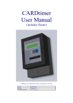
Download CARDtimer User Manual
Transcript
CARDtimer
User Manual
CARDtimer User Manual ver 009 2011-04-15.docx
Author:
Checker:
Printing date and time:
Steve Heaton
Jason Paul
15/04/11, 13:00
CARDtimer User Manual ver 00a 2011-04-15.docx
Contents
Page
1 REVISION RECORD ..................................................................................................................... 3 2 INTRODUCTION............................................................................................................................ 4 2.1 2.2 2.3 2.4 GENERAL ............................................................................................................................................ 4 EXAMPLE APPLICATIONS: ................................................................................................................... 4 KEY FEATURES ................................................................................................................................... 5 BUSINESS BENEFITS ............................................................................................................................ 5 3 DEFAULT REGISTER VALUES ................................................................................................. 6 3.1 SETTINGS ............................................................................................................................................ 6 4 SPECIFICATION ............................................................................................................................ 7 4.1 4.2 4.3 4.4 ELECTRICAL ........................................................................................................................................ 7 PHYSICAL ............................................................................................................................................ 7 TIMING ................................................................................................................................................ 7 MISC ................................................................................................................................................... 7 5 INSTALLATION INSTRUCTIONS ............................................................................................. 8 5.1 DIMENSIONS........................................................................................................................................ 8 5.2 DRILLING TEMPLATE .......................................................................................................................... 9 6 CONNECTION .............................................................................................................................. 10 6.1 CONNECTION – SINGLE LOAD .......................................................................................................... 10 6.2 CONNECTION – AUXILIARY LOAD (OPTION A) ................................................................................ 10 7 PROGRAMMING INSTRUCTIONS ......................................................................................... 11 7.1 INTRODUCTION ................................................................................................................................. 11 8 FIXED REGISTERS ..................................................................................................................... 13 8.1 8.2 8.3 8.4 8.5 8.6 8.7 8.8 8.9 8.10 INTRODUCTION ................................................................................................................................. 13 NUMCARDS ................................................................................................................................... 13 REBOOTS ........................................................................................................................................ 13 EQUIPTYP....................................................................................................................................... 13 TOTLSEC ........................................................................................................................................ 14 TIMECRED ..................................................................................................................................... 14 MAXCRED ...................................................................................................................................... 15 TIMEWARN .................................................................................................................................... 15 SOUND ............................................................................................................................................ 15 TICK ............................................................................................................................................ 16 9 VARIABLES .................................................................................................................................. 17 9.1 INTRODUCTION ................................................................................................................................. 17 9.2 EXAMPLE OF CHANGING A REGISTER............................................................................................... 17 9.3 COMPLETING PROGRAMMING ........................................................................................................... 19 10 10.1 USER INSTRUCTIONS ............................................................................................................... 20 INTRODUCTION ............................................................................................................................ 20 PAGE 2 of 21
CARDtimer User Manual ver 00a 2011-04-15.docx
1
REVISION RECORD
Version no.
004
Revision Date
2011-02-12
Reason for Change
First issue for firmware version
11BWR1001 1BS0000
005
2011-03-25
First issue for firmware version
ABXR100C ABSC0000
006
2011-04-03
First issue for firmware version
ABXR100D ABSC0000
007
2011-04-09
First issue for firmware version
ABXR100E ABSC0000
008
2011-04-11
First issue for firmware version
ADWR100FADCC
009
2011-04-15
First issue for firmware version
ADXR100GADSC
00a
2011-05-15
First issue for firmware version
ADXR100JADSC
PAGE 3 of 21
CARDtimer User Manual ver 00a 2011-04-15.docx
2
INTRODUCTION
2.1
General
2.1.1
The CARDtimer is ideal for all situations where the duration of electricity
usage needs to be controlled, and it is desirable to avoid coin timers with
their inherent security, reliability and emptying issues.
2.1.2
The timer owner sells disposable cards to the customer, and sets the timer
to provide an appropriate duration of electricity usage for the appliance.
2.1.3
For example, for a sun-bed, the owner may sell the cards to the customers
at £3.50, and set the timer to provide 30 minutes of power to the sun-bed.
2.1.4
The cards can be sold in pounds, euros or any other currency.
2.1.5
The standard cards are imprinted “ONE CREDIT”. Other legends are
available from your supplier.
2.1.6
Timers with Option A have a second controlled output which stays closed
for 5 minutes after the main contact has opened. This may be used for fans
or auxiliary lighting.
2.1.7
Custom software applications can often be developed on request.
2.2
Example Applications:
•
•
•
•
•
•
•
•
•
•
•
Gym equipment, Sun-beds, Tanning Booths
Snooker Table Lights
Vehicle cleaning – Vacuums, Jet-wash, etc
Squash Court and Sports Field Lighting
Washing Machine (operating the water inlet solenoid)
Gaming Machines (control power to the display)
Showers (including electric showers up to 25kW)
Heating (control live supply to gas or oil heating system)
Hairdryers & Hair Straighteners
Air-conditioning
Rented Workshops, Garages, & Premises
PAGE 4 of 21
CARDtimer User Manual ver 00a 2011-04-15.docx
2.3
Key Features
•
•
•
•
•
•
•
•
•
•
•
•
•
•
•
2.4
Uses secure disposable magnetic cards
When card is inserted, time credit is copied from the card to the timer
Multiple cards may be entered in one session
Card is erased and permanently marked
Cardtimer display counts down in hours, minutes and seconds
User settable duration of 0 to 999,999seconds (0 to 227hrs) per card
Maximum accumulated time is unlimited
User friendly 16 character LCD display
Master Programming Card allows settings to be easily changed
Switches up to 100A and can supply up to 25kW of load
Red led clearly indicates the supply contactor is closed
Optional warning beeper when credit running out
No battery replacement required – design lifetime 20 years
Independent of currency
Landlord Mode (dispenses electricity without charge) for friends and
family use
Business Benefits
2.4.1
Incidental sales resulting during the purchase of cards
2.4.2
Sales are not lost due to consumers not having the correct change
2.4.3
Ability to flexibly change the time and cost per session
2.4.4
No attraction for theft
2.4.5
Better control of cash (no need to periodically empty meters of coins)
PAGE 5 of 21
CARDtimer User Manual ver 00a 2011-04-15.docx
3
DEFAULT REGISTER VALUES
3.1
Settings
3.1.1
The CARDtimer has various registers which can be adjusted by the user,
depending on the application.
3.1.2
The default values are shown here, together with any adjustments made by
your supplier or electrician.
Value
Factory Adjusted
Setting Value
EQUIPTYP
000
[BLANK]
text to be displayed alternately with INSERT
CARD, when the credit has reached zero
TIMECRED
600sec
number of seconds credited for each card
inserted
MAXCRED
1200s
number of seconds of credit which can be
added by the user
TIMEWARN
60sec
start of warning sound that credit is running
out
SOUND
ON
sound confirmations when keys are pressed,
cards are inserted, or the display shows a
message
TICK
ON
tick sound each time a second elapses
PAGE 6 of 21
CARDtimer User Manual ver 00a 2011-04-15.docx
4
4.1
4.2
SPECIFICATION
Electrical
Voltage Rating
220-250Vac 50Hz
Current rating
100A main contactor
5A auxiliary contactor
(option A timers only)
Maximum cable diameter
8mm (main terminals)
3.2mm (auxiliary terminals)
Physical
Height
Width
Depth
Weight
4.3
Timing
Duration per card (user settable)
Maximum time credit (user settable)
Timing accuracy
4.4
171mm
124mm
92mm
950g
1 to 999,999 sec (0 to 277hrs)
unlimited
1%
Misc
Design lifetime
IP rating
20yrs
IP20
PAGE 7 of 21
CARDtimer User Manual ver 00a 2011-04-15.docx
INSTALLATION INSTRUCTIONS
AR
D
tim
er
92mm
C
C
AR
D
tim
er
Allow 50mm clear below the timer for wiring connections.
124mm
tim
er
171mm
D
5.1.1
Dimensions
AR
5.1
C
5
CARDtimer
Project:
Subject: Dims
File Ref: Cardmeter Connection ver 001 2011-02-13.vsd
Issue date: 9/4/11 by
PAGE 8 of 21
CARDtimer User Manual ver 00a 2011-04-15.docx
5.2
Drilling Template
PAGE 9 of 21
CARDtimer User Manual ver 00a 2011-04-15.docx
6
CONNECTION
6.1
The CARDtimer is able to support a load of up to 100A from the main
terminals.
C
AR
D
tim
er
C
AR
D
tim
er
6.1.1
Connection – Single Load
Phase
Fuse or MCB
(max 100A)
Neutral
Phase
MAIN
LOAD
Neutral
Line
CARDtimer
Project:
Subject: connection
File Ref: Cardmeter Connection ver 001 2011-02-13.vsd
Issue date: 9/4/11 by
6.2
Connection – Auxiliary Load (Option A)
6.2.1
The CARDtimer is capable of switching an auxiliary load of up to 5A
(option A timer only).
6.2.2
The relay contact within the timer opens 5 minutes after the main contact
opens, and is ideal to operate background lamps, fans and so on after the
main contact has opened.
PAGE 10 of 21
CARDtimer User Manual ver 00a 2011-04-15.docx
7
PROGRAMMING INSTRUCTIONS
7.1
Introduction
7.1.1
The CARDtimer can only be programmed using the master programming
card originally supplied with the timer (replacements are available from
your supplier).
7.1.2
The master programming card is inserted in the card slot on the front of
the CARDtimer, magnetic strip upwards. This can be done whenever
“INSERT CARD” is displayed, or when the timer is running (timer
continues to count down in the background during programming).
7.1.3
The card needs to be inserted in one smooth action. If the card is inserted
too fast, or too slowly, then the timer will display “CARD ERROR”.
7.1.4
If this happens, wait for the timer to display “INSERT CARD” and then try
again.
7.1.5
When you have successfully inserted the master programming card, the
display will show “*PROGRAMMING*”, and will cycle through the
registers as shown below. The actual values may vary slightly depending
on the software version.
PAGE 11 of 21
CARDtimer User Manual ver 00a 2011-04-15.docx
*PROGRAMMING*
ONE SECOND
VIEW REGISTERS
GREY> MOVE RIGHT
NUMCARDS
12
BLUE> SWAP VALUE
Number of microprocessor reboots since manufacture
is displayed. Initial value 0 (note 1), cannot be reset.
REBOOTS
2
WAIT> WHEN DONE
Equipment type label, which is displayed alternately
when INSERT CARD is shown
EQUIPTYP
010
0
TIMECRED 000600s
Number of seconds credited by each card inserted. Can be adjusted at
this point. Initial value 600s (10mins). Range 0 to 999,999sec per card.
TOTLSEC
7200
MAXCRED
1
1200s
Maximum number of seconds of credit which the
user can add. Initial value 1200s (20mins).
TIMECRED
600
TIMEWARN
0 00s
Point at which audible warning of that time is about to expire.
Can be adjusted. Range 0-199sec.
1200s
EQUIPTYPE
0
010
Number of cards inserted since manufacture is
displayed. Initial value 0 (note 1), cannot be reset.
Total number of seconds sold since manufacture is
displayed. Initial value 0 (note 1), cannot be reset.
Number of seconds credited by each card inserted is displayed.
Can be set by the user. Initial value 600s (10mins).
Maximum number of seconds of credit which the
user can add. Initial value 1200s (20mins).
Point at which audible warning of that time is
about to expire. Initial value 60s.
Whether the sounder is enabled or not is displayed. Can
be set by the user. Initial value ON.
Whether the timer ticks each time a second is counted down
is displayed. Can be set by the user. Initial value ON.
MAXCRED
Sets the equipment type label, which is displayed
alternately when INSERT CARD is shown
TIMEWARN
60s
SOUND
O
ON/OFF
Whether the sounder is enabled or not. Can be set either ON or
OFF.
SOUND
ON
TICK
O
ON/OFF
Whether the timer ticks each time a second is counted down. Can
be set either ON or OFF.
TICK
ON
PROGRAMMING DONE
INSERT CARD
Note 1: These values may be modified
by factory tests before dispatch.
COURT LIGHTS
PAGE 12 of 21
CARDtimer User Manual ver 00a 2011-04-15.docx
8
FIXED REGISTERS
8.1
8.1.1
8.2
Introduction
Once in programming mode, the CARDtimer will provide information from
its internal registers. These registers contain records of various values,
some of which are set to zero at the time of timer manufacture. It is not
possible to subsequently reset or change these registers, so they provide a
true record of the usage of the timer.
NUMCARDS
8.2.1
This register records the number of cards successfully used by consumers
since the manufacture of the timer and this value will increase by one each
time a card is inserted.
8.2.2
This register is set to zero at the time of manufacture and cannot be reset.
Note, this value may be modified by factory tests before dispatch.
8.3
REBOOTS
8.3.1
This register records the number of reboots of the microprocessor since the
manufacture of the timer. A reboot occurs each time the mains fails. If
there are an excessive number of reboots it may indicate that there have
been attempts at tampering with the timer.
8.3.2
This register is set to zero at the time of manufacture and cannot be reset.
Note, this value may be modified by factory tests before dispatch.
8.3.3
This number should be noted down after installation, and any significant
increase investigated.
8.4
EQUIPTYP
8.4.1
This register records the text to be displayed alternately with INSERT
CARD, when the credit has reached zero.
8.4.2
This register is set to zero at the time of manufacture and can be altered by
the user.
EQUIPTYPE
010
PAGE 13 of 21
CARDtimer User Manual ver 00a 2011-04-15.docx
8.4.3
The acceptable values are as follows:
0 No equipment type (ie blank)
1 SUNBED
2 TANNING BOOTH
3 SNOOKER TABLE
4 LIGHTS
5 HEATING
6 HEATER
7 VAC
8 VACUUM
9 POOL LIGHTS
10 COURT LIGHTS
11 SQUASH COURT
12 GAMES MACHINE
13 PITCH LIGHTS
14 WASHING MACHINE
15 TUMBLE DRIER
16 SHOWER
17 HEATING SYSTEM
18 HAIR DRIER
19 HAIR STRAIGHTNERS
20 AIRCON
21 AIRCONDITIONING
22 SHOWER 1
23 SHOWER 2
24 POWER PLATE
25-255
8.5
No equipment type (ie blank)
TOTLSEC
8.5.1
This register records the number of seconds purchased by consumers since
the manufacture of the timer. This value will increase by the amount of
time purchased by each card when it is inserted.
8.5.2
This register is set to zero at the time of manufacture and cannot be reset.
Note, this value may be modified by factory tests before dispatch.
TOTLSEC
8.6
7200
TIMECRED
8.6.1
This register records the number of seconds credited for each card inserted.
8.6.2
This register is set to 600sec at the time of manufacture.
8.6.3
The value can be changed (see next section).
PAGE 14 of 21
CARDtimer User Manual ver 00a 2011-04-15.docx
8.6.4
If TIMECRED is set to zero, the CARDtimer erases any remaining time,
and enters LANDLORD MODE. In this mode the meter dispenses
electricity without the user needing to enter cards. This mode is ideal for
testing purposes, or friends and family.
8.6.5
To return to normal operation, program the TIMECRED register to a value
other than zero.
8.7
MAXCRED
8.7.1
This register sets the number of seconds of credit which can be added by
the user.
8.7.2
For instance, if MAXCRED is set to 1200 (seconds) and TIMECRED is set
to 600 (seconds), then a maximum of two cards can be inserted at a time.
Another card can only be inserted after the displayed credit falls below 600
seconds.
MAXCRED
1200s
8.7.3
MAXCRED can be set between zero and 999999seconds.
8.7.4
If accepting credit from a card will cause the credit to exceed MAXCRED,
the display shows CREDIT FULL.
8.8
TIMEWARN
8.8.1
This register shows when consumers will be warned that their credit is
running out. For example, if the TIMEWARN is set to provide 60s then a
warning sound will be produced by the timer one minute before the credit
runs out. This gives consumers a chance to purchase additional credit.
8.8.2
This register is set to 60sec at the time of manufacture. It can be changed
by the user (see elsewhere in this section). Range is 0-199 seconds.
8.9
SOUND
8.9.1
This register records whether the timer will sound confirmations when keys
are pressed, cards are inserted, or the display shows a message.
8.9.2
Setting SOUND to OFF automatically sets TICK to OFF.
8.9.3
This register is set to ON at the time of manufacture. It can be changed to
OFF by the user (see following section).
PAGE 15 of 21
CARDtimer User Manual ver 00a 2011-04-15.docx
8.10 TICK
8.10.1
This register records whether the timer will produce a tick sound each time
a second elapses. This can be useful to alert users that the timer has started,
and their credit has begun to be used up.
8.10.2
Setting SOUND to off automatically sets TICK to OFF.
8.10.3
This register is set to ON at the time of manufacture. It can be changed to
OFF by the user (see following section).
PAGE 16 of 21
CARDtimer User Manual ver 00a 2011-04-15.docx
9
VARIABLES
9.1
Introduction
9.1.1
The variables in this section are settable by the user. You will need to have
entered the programming mode using the master programming card, see
the previous section.
9.1.2
Registers which may be adjusted are displayed with a black flashing cursor,
at the digit or value position which can be changed.
9.1.3
If a key is not pressed, the CARDtimer will move on to the next settable
value after 5 seconds.
9.1.4
If you change a value, wait for 5 seconds after your last key press. The
time will accept you value and move to the next settable value.
9.1.5
If you make a mistake, just let the timer step through all the settable values,
and then start again, by inserting the master programming card again.
9.2
Example of Changing a Register
9.2.1
The TIMECRED register shows the number of seconds that will purchased
by consumers for each insertion of a card. For example, if you want to
provide 25 minutes for each insertion of a card (1500 seconds), then set this
value to TIMECRED 1500s.
9.2.2
The display will show the present value, with a flashing cursor.
9.2.3
Use the grey button to move the cursor under the digit you wish to change.
PAGE 17 of 21
CARDtimer User Manual ver 00a 2011-04-15.docx
9.2.4
Press the blue button to change the digit value.
9.2.5
Press the grey button to move on to the next digit.
9.2.6
To change the digit to a 5, press the blue button repeatedly until 9 shows,
and then continue pressing and the value step through 0, and count up to 5.
9.2.7
The value is now changed to 1500s, wait 5 seconds and the timer will
move on to the next settable value.
9.2.8
If you have made a mistake, then wait until the PROGRAMMING DONE
message has displayed, and then start again inserting the master
programming card.
PAGE 18 of 21
CARDtimer User Manual ver 00a 2011-04-15.docx
9.3
9.3.1
Completing Programming
Finally, after the opportunity to change any of the variables, the timer will
display PROGRAMMING DONE and then revert to the timer function.
PAGE 19 of 21
CARDtimer User Manual ver 00a 2011-04-15.docx
10 USER INSTRUCTIONS
10.1 Introduction
10.1.1
The CARDtimer provides electricity for a set amount of time whenever a
card is inserted.
10.1.2
A card can be inserted whenever “INSERT CARD” is displayed, or when
the timer is counting down.
10.1.3
Each card needs to be inserted in one smooth action. If the card is inserted
too fast, or too slowly, then the timer will display “CARD ERROR”.
10.1.4
If this happens, wait for the timer to display “INSERT CARD” and then try
again.
10.1.5
If you insert a card which has previously been used, the card will be
ignored.
10.1.6
When you have successfully inserted the card, credit will be added to the
timer, and the countdown will begin. The red light on the front of the timer
will light.
10.1.7
When the time is nearly elapsed, the timer may make a warning sound, and
then the electricity will be cut off. The red light on the front of the timer
will go out.
10.1.8
You can insert another card at any time to extend the amount of time
purchased.
PAGE 20 of 21
CARDtimer User Manual ver 00a 2011-04-15.docx
10.1.9
If you have card problems, the meter owner can interrogate internal
registers of the meter to determine what cards have been inserted and if any
issues have been encountered in processing your cards.
PAGE 21 of 21







![4403002491_712_716 menu_EN_A [s]](http://vs1.manualzilla.com/store/data/005650300_1-96030b29e24dd373b0bced3bef593dda-150x150.png)

