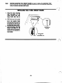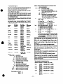
1
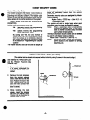
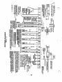
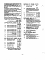
4110DL
INSTALLATION
INSTRUCTIONS
CONGRATUtATIONS
on your purchase of the V’AGE
41lODL!
The. purpose of these Installation Instructions is to give you a brief
overview of the VANTAGE 4110DL system, and provide instructions for- installing -a basic system.
Our SALES and
As always, ADEMCO
is there for YOU!
TECHNICAL SUPPORT sfaff are eager to assist you in any way they
can, so don’t hesitate to call, for any reason!
East Coast Te&id
Support: l-800-645-7492 (8 a.m.-6p.m. E.S.T.)
West Coast Technicd Support: l-80&58-9469 (8 a.m.-j p.m. P.S.T.)
PLEASE,
Before you call Technical Support, be sure you have:
l
Checked all wiring connections and fuses.
l
Determined that the power supply and backup battery are
supplying proper voltages.
l
Verified your programming
information
where applicable.
l
Noted the proper model number of this product, and the
version level (if known) along with any documentation
that came with the product.
l
Your Ademco customer number and/or company name.
Having this information handy will make it easier for us to serve
you quickly and effectively.
Again,
CONGRATULATIONS,
and WELCOME
I
ABOARD!
FOR YOUR CONVENIENCE, two easily removable
Programming
Forma have been included at the
center of thir manual.
I
-2-
CONTENTS
Specifications ...............................................
of this Alarm System .............
Canadian DCC Statement ............................
FCC Statement .............................................
Limited Warranty ..........................................
General Information .........................................
Remote Programming and Control .................. :
Zone Types Availabta for Selection.. ........ ....... .4
4-Digil Security Codes .................................... 5
Wiring Connections ........................................
Mounting the Console(s) ................................. 3
Programming the Security Control. ................. .9
Specific Address Programming instructions ....I 0
Testing the System ....................................... 15
Accessories ................................................. 15
GENERAL
The Limitations
.20
Diagrams
Installing the Lo& (lf Used) .............................. 5
lnstaliing the 411 ODL Circuit Board ................. .6
Summary of Connections ................................
Programming Form ...................................... .1”3
INFORMATION
that the unit can be reprogrammed many times
(unlike units equipped with PROMS) and that information which has been programmed will not be lost
in the event of a complete loss of power.
The system provides communication capability
(central station reporting, etc.) over existing telephone lines. In addition, it can be uploaded, downloaded, or controlled via your computer and Hayes
Modem.
This system includes an alarm output rated at
2 amps. Throughout the manual, wherever
The VANTAGE (No. 4110DL) is a micropmcessorbased security control which provides up to 6 wired
zones. The security control is housed in a wallmounted metal cabinet measuring 12-112. (316 mm)
wide x 14-l/2” (368 mm) high x 3” (76 mm) deep,
and can be used with a console equipped with a
multifunction 12.key digital keypad and a numeric
and fixed English status LCD display (4127).
Optionally, a No. 4137 may be used or a No. 5330
Alpha Console (select for Vector device, as described in the 5330’s installation instructions) may be
used with the control to provide programmable
English language zone descriptors and status indications. The system may also be armed and disarmed using a keyswitch.
Connections to the security control are made via a
2%terminal connector block which is used to interface to the wired loops, plug-in transformer, teiephone line, remote consoles, external alarm
sounder(s), etc.The security control can be easily
programmed from any of the above remote consoles. Programmed options to establish specific
alarm and reporting features are stored in electrically
erasable, non-volatile EEROM memory. Thii means
REMOTE
16
.I7
.16
20
reference Is made to Alarm Output Ratings,
they assume a fully charged battery Is connetted unless the UL rating Is stated. The
battery is periodically tested and if it cannot sustain a
bad, a bw battery message is displayed and can be
reported to the central station.
Zone Characteristics
Zones l-6:
Proarammabie Zones, EOLR supeGsed,
N.O. or N.C. sensors,
200600 msec response (Zones
l-6). fast 10 - 15 msec response
optional (Zone 3).
PROGRAMMING
The No. 4llODL can be remotely programmed from
an IBM compatible Personal Computer (PC), a Hayes
Modem, and Ademco’s V-LINK@ Software
Programming the No. 4llODL from a remote bcation
is protected against compromise by someone attempting to defeat the system, using multi-levels of
security protection:
1. Security Code Handshake: An 8-digit
download ID code must be matched between
the No.41 1ODL and the downloader.
2. Slte lnltiated Remote Programming: The
installer or subscriber initiates the callback from
the subscriber premises (by pressing MASTER
CODE + # + 1). Ail parameters can then ,be
downloaded via the phone lines using a personal computer.
AND CONTROL
3. Station Initiated
Remote Programmlng:
The operator calls the sfte from your off ice to initiate the download call. The 4110DL hangs up
and then calls back the PC via the preprogrammed telephone number. The unit can then
be uploaded, downloaded, or controlled from
your offiie.
4. Data Encryptlon: Data passed between the
PC and the No. 4llODL is encrypted for security
so that it is very difficult for a foreign device
tapped into the phone line to take over communication and substitute system compromising information.
-3-
Equlpment Required
At the premises:
and the proper dialer reports are sent to the central
station. The consoles will become .active after the
download communication is terminated. The detailed
operation of the download functions is covered in
the installation instructions for the 413OPC
Download Software Diskette.
Remote Programmlng Advisory Notes:
Alarm and trouble reporting may be delayed
during the time that the system and the
Downloader are linked to each other following a
valid exchange of codes, but the proper message will get through to the Central Station after
the link is broken.
Keypad entries are ignored during the time interval stated above.’
A copy of the program downloaded may be produced from the IBM PC compatible computer,
using the product’s internal report generator,
when an optional printer is connected (consult
your PC manual for proper printer and connec‘tions).
Program Download Time-Less than 45 seconds for a complete program.
4110DL and console
At the Installer’s &flce/home:
l
An IBM PC compatible computer, a Hayes
brand Smartmodem 1200 (Level 1.2 or
higher external or Level 1.1 or higher internal style), No. 4130PC Downloading Software Diskette (Rev. 1.78 or higher), and ap
propriate interconnecting cables.
l
Programmlng:
The downloading system can perform many functions when in communication with the control unit.
Besides uploading and downloading, the status of
the system can be observed and various commands
can be initiated.
Notes: After the 411 ODL and the PC have established valid communication, each console on the
system will become inactive and will display “Cc’.
The 411ODL, however, will still be scanning its zones
and looking for alanns. lf an alarm does occur, after
communication is broken off, alarms are sounded
ZONE TYPES AVAILABLE
For each zone used, one of the following zone types
must be selected:
0. Zone Disabled
1. EnttyiExlt Burglary. Assigned to sensor6 on
dOOE tMiigh which entry and exit will normally
take place when the system is armed.
2. not used
3. Perimeter Burglary. Normally assigned to all
aen6or6 on exterior doors and windows requiring
instant alarm.
4. Interior, Follower. Delayed alarm only if the
Entry/Exit zone is faulted first; otherwise, produces an instant alarm. Assigned to zone covering an area such as a foyer or lobby through
which one must pass upon entry to reach the
keypad to disarm the system. Designed to provide instant intrusion alarm in the event an intruder hides on the promises prior to the system
being armed or gains access to the premises
through an unprotected area.
5. Trouble by Day/Alarm by Nlght. Can be
assigned to a zone which contains a foil-protecteddoororwirbdow(6ucha6ina6tore),ortoa
zone covering a %ensitiie area such as a stock
room, drug supply room, etc., or other controlled
access area where immediate notification of an
FOR SELECTION
6.
7.
8.
9.
entry is desired. During the disarmed state (day),
the system will provide latched Console annunciation (and central station report, it desired) of
opening6 or troubles (such as sensor malfunctions or foil breaks). During the armed state
(night), violation6will initiate an alarm.
24-hour Silent Alarm. This type generally
assigned to a zone containing an Emergency
button that is designed to initiate an alarm report
to the Central Station, but which produces no local diilays or alarm sounds.
24-hour Audlble Alarm. This type also assigned to a zone containing an Emergency button, but which will initiate an audible alarm in addition to an alanrr report to the Central Station.
24-hour Auxlllary Alarm (Console sounder
only). This type assigned to a zone containing a
button for use in personal emergencies, or to a
zone containing monitoring devices such as water sensors, temperature sensors, etc. Designed
to initiate an alarm report to the Central Station
and only provides %onsole warning sounds and
Wmdispiays.
.
Supervlsed Fire (alarm on shoWtrouble on
open). Fire zone may not be bypassed. Only
usable on Zone 5 or Console Panic.
-4-
f? /
.
41DIGIT
SECURITY
Master Security Code:
to three secondary codes; it can also be USedto remove all Secondary Code6 from the System
(individually).
’
Secondary security code6 are assigned by Master
Code as follows:
Master Code + CODE key + User # (2 - 4)
+ Secondary Code
The system will emit a single beep when each
secondary code ha6 been successfully entered.
Note:
When a secondary code Is inadvertently
repeated for different users, or one user’s
code is another’s dUre66 code, the lower
user number will take priority.
Individual secondary security codes can be deleted
by user #l (with Master Code) as follows:
Master Code + CODE key + User # (2 - 4)
Note:
All security codes, master and Secondary,
permit access to the system for arming,
disarming, etc.
The installer programs tt&.Master Code initially as
part of the programming procedure (see “Programming the Security Control”). The Master code
petit6 re-entry into the programming mode and also
allows access to the normal functions of the system.
[ 1[][ J[ ] Master Code (User #l), assigned during
programming.
Installer exits programming mode with:
‘98
(prevents re-entry into programming
mode with Master code).
‘99
(allow6 re-entry into programming
mode with Master code).
By exiting with ‘98, the only method of
getting back into the programming mode
from the console is to completely depower
the system and follow the procedure noted
in the section on “Programming the Security
Control’.
The Master security code can be USedto assign up
INSTALLING
CODES
THE LOCK (IF USED)
(The cabinet can be closed and secured without a lock by using 2 screws in the covets edge.)
Use Ademco No. P3422 Cam Lock
and No. P3422-1 Push-On Clip
(Retainer Clip).
1. Remove the cabinet cover.
It is easily removable for
servicing and is easily reinstalled.
2. Remove the lock knockout
from the control cabinet
cover. Insert the key into the
lock. Position the lock in the
hole making certain that the
latch will make contact with
the latch bracket when the
door is closed.
3. While holding the lock
steady, insert the retainer
clip into the retainer slots.
Position clip as illustrated to
facilitate easy removal.
-5-
r
.-_d_-_
~--
Note:
BEFORE MOUNllNG THE CIRCUlT BOARD, be sure to remove the appropriate metal
knockout6 from the cabinet. DO NOT AITEMPT TO REMOVETHE KNOCKOUTSAFTER THE
CIRCUIT’BOARD HAS BEEN INSTALLED.
INSTALLING
1. Hang two long mounting
clip6 (provided) on the
raised cabinet tabs (see
lower detail side view at
right).
2. Insert the top of the circuit
board into the Slot6 at the
top of the cabinet. Make
sure that the board rests on
the Correct NW (SW the Up
per detail side view at right).
3. Swing the base of the board
into the mounting clips and
secure the board to the
cabinet with the accompanying screws (as illustrated in
tower detail).
THE 4110DL
CIRCUIT
BOARD
DETAIL SIDE VIEW
OF BOARDS INSERTED
INTO SLOTS
I
WIRING
CONNECTIONS
(See Summary of Connections
IMPORTANT:
:
Dlagram)
Do not connect the battery, or plug In the AC transformer,
until all other wlrlng connectlons have been completed.
Groundlng the System
Terminal 21 is the earth ground connection point. In order for the protective device6 in this product to be effective,
the designated temrinal must be terminated in a good earth ground. The following are examples of good earth
gmUnd6 available at most installations:
Metal cold water plpe: Use a non-corrosive metal strap firmly secured to the pipe to which the lead is
electrically connected and secured.
AC power outlet ground: Available from 3-prong, 125 VAC power outlets only. To test the integrity of the
ground terminal, use a 3-wire circuit tester with neon lamp indicators, such as the UL Listed Ideal Model
61-035, or equivalent, available at most electrical supply Stores.
TERMINALS
1 & 2: AC Input from No. 1321TTF2 okra-in transformer, in U.S.A. (16.5 VAC, 25VA)
NOTE: In Canadian installations, a 1321CN
transfoner must be Used.
3: Alarm relay output(+), 12 VDC, 2.OA maximum
(600 rnA max. Alarm plus Aux. Power, for UL
usage).
4: Alann Output / Auxiliary Power / Fire / Console
/O%$al Keyswitch (BtACK lead) Ground (-)
5:
6:
7:
8:
9:
10:
11:
12:
13:
14:
15:
16:
17:
18:
19:
20:
21:
Zone 4
Zone 5
Zones 5 and 6 Return.
Zone 6
Handset (TIP).
Handset (RING).
Incoming Phone Line (TIP).
Incoming Phone Line (RING).
EARTH GROUND (a proper earth ground must
be provided to protect the system from lightn/ng and electrostatic discharge damage).
t Home run each console. Use no more than 220
of #22 wire or 550’ of #18 wire.
Warning: To prevent the risk of electrical Shock,
disconnect the telephone line at the Telco jack before servicing the unit.
Auxiliary / Fire / Console / Optional Keyswitch
(RED) Power.
+12 VDC at 500 naA max. t.
Data In from Console / Optional KeySWitCh
(GREEN)*.
Data Out to Console / Optional Keyswitch
(YELLOW)*.
Zone 1. (When Zones are used, a 1,000 Ohm
EOLR should be wired between the farthest
sensor connected to the zone terminal and
the tow side of the zone.)
Zones 1 and 2 Return.
Zone 2
Zone 3
Zones 3 and 4 Return.
MOUNTING
RED LEAD: Battery(+). When AC is present,
13.8 VDC is being developed to recharge a gel lead
acid battery and when AC is absent, 12 VDC current
is drawn from the battery. Battery lead reversal will
Mow the battery .fuse.
BLACK LEAD:Battery (-).
THE 4127
CONSOLE(S)
4. Pass the interface wiring through the opening in
the backplate and then mount the backplate to
the wall surface with screws.
5. Splice the interface wiring to the console wires.
InSulated SOlderleSS Wire splices (such a6
Ademco No. 311) may be USedfor splicing.
6. Attach the main body of the console to the wallmounted backplate. The console is property attached when it is Screwed to the backplate by
top and bottom screws.
1. Separate the console from its backplate by removal of the two screws on the top and bottom
edges.
2. Use the backplate to mark the positions on the
wall for the screw mounting hole6 and the cutout for the interface wiring. Use wall anchor6 tot
the screws and make the cut-out in the wall no
larger than indicated on the template. The backplate is designed to be directly mounted to either a single or double gang electrical box.
Pull the interface wiring in the wall through the
cut-out.
-7-
‘I
I
I
I
I
I
!
c
-8-
PROGRAMMING
*HE GE&STY
Installer options are stored in non-removable,electrically erasable, non-volatile EEROM memory.’ These
optiins must be programmedfor the particular installation to establish its specifii alam, and reportingfeatures. The searrity control may be programmed from
a remote console.
When programming, the field number will be displayed on the LCD display: also, each entry is displayed as it is keyed in. After programming, values
that have been entered in each field can be reviewed and, if necessary, modified.
*Note: lt is possible to program the system at any
time - even at the installer’s premises prior to the actual installation. Simply apply power tetiporarily to
the control and then program the unit as desired.
When programming from the console, note the following:
1. Enter the Programming mode by simultaneously
depressing the [‘I and [#I keys wlthln 50
CONTROL
The following is a description of commands necessary for programming:
FUNCTION
PROCEDURE
ENTER
PROGRAMMING
MODE:
1. POWER UP, then depress
r)and [#] simultaneously
within 50 seconds of powering up.
OR
2. Initially, Key: 4 + 1 + 1 + 0
plus CODE key + 0.
OR
3. After Master Code is programmed, key: Nl@ter
Code + CODE key + 0.
(If ‘98 was used to exit previously, method 1 above must be
used to ente! the program mode
again.)
l 99 (allows m-entry to proE~RAMMING
grammingmode via Type 3
MODE:
entry method above)
‘98 (inhibits re-entry to programmingmode via Type 3
entry method)
ADVANCE TO FIELD: r] + ADDRESS (e.g. 21,
35, 52, etc.).
PROGRAMFIELD:
r] + ADDRESS, followed
by data entries.
ERASE FIELDS:
[‘I + ADDRESS + r] (only
applies to Addresses 40
thn, 43 and 94.)
READ FIELD:
[nr] + ADDRESS
SPECIAL
MESSAGES
oc=
OPEN ClRCUlT (no communicationbetween
the Console and the Ccntfcl).
EE = ERROR (programentry mistake, re-enter the
data).
After powering up, AC, dl (disabled) and NOT
READY will be displayed after approximately 4
seconds.Thii will reverl to READY in appx. 1 minute,
which allows PIRS, etc. to stabilize. To bypass this
delay, press: # + 0.
seconds
after power Is applied
to the
Control, or subsequently by keying the code
4 + 1 + 1 + 0 followed by depression of
CODE + 0 keys. Once a Master code is
programmed, use ii instead of 4110 to gain
access to the Programming mode. If the
Programming mode was exci&$f previously
using a ‘96. it will prevent entry into the
Programming mode by the use of the Master
Code + CODE + 0.
2. Immediately following entry into the program
mode, 20 will be displayed. (If a 5330 console is
used, 00 will be displayed. Enter l 20 to access
the programming start point). Following the
above display, the system is ready to accept entries for Address 20.
To program a data field, key r) plus Address
(for example, ‘21). then make the required entry.
To simply review a data field, key [#I plus
Address.
3. When a data field has been completely programmed, the console will normally “beep” three
times and then automatically proceed to, and
display, the next data field address to be programmed (if not, key r] plus the address of the
next field to ba programmed).
4. If the number of digits that you enter in the data
field is less than the maximum permitted (for example, phone number), then the console will
display the last data entered. To proceed, the
next data field address to be programmed must
then be entered (for example, ‘42).
5. If an address is improperly entered, the console
will display EE. Simply m-enter or # plus the
number.
l
-9-
Note:
The followlng
progremmlng
InformatIon
Shows
Factory Default Settlngs withln brackets:
[ ]
SYSTEM ARMING (*20-•23)
MASTER SECURITY
*20
‘23
ZONE
‘29
l 30
CODE
RESPONSE PROGRAMMING l 29-•39
‘40
FIRE TIMEOUT
DISABLE
[0 ] Enter 1 to disable the sounder timeout
for fire or 0 to enable ft.
ALARM BELL TIMEOUT
‘41
20 not used
3= PERIMETER, Burglary
4= INTERIOR, FOLLOWER, Burglary
5= TROUBLE BY DAY/ALARM BY NIGHT, Burglary
6= 24 Hr (silent)
7= 24 Hr (Audtte)
8=24Hr (Aux)
S= FIRE, Fields ‘35 8 l 37 onty
‘32
RESPONSE TYPE FOR ZONE 2
[4 ] Enter 1 dlltl
‘33
RESPONSE
TYPE
[3 ] Enter 1 digil
RESPONSE
TYPE
[3 ] Enter 1 diit
RESPONSE
TYPE
[9 ] Enter 1 digit,
RESPONSE
TYPE
‘34
l 35
‘36
l 37
FOR ZONE
PRIMARY
PHONE
No.
‘42
Enter up to 12 digits, g-9. Do not fill unused
spaces. End field by entering ‘42 lf not filled.
To clear entries from field, press ‘41’.
Note: Back-up reporting (8 calls are made to
the secondary phone number if no
acknowledgment is received after 8 attempts
to the primary number) is automatic only if
there is a secondary phone number.
SECONDARY
PHONE No.
I
,P
‘\
f’
~ltIl~IIHIHIXltI
See above. End field by entering ‘43 if not
filled. To clear entries from field, press l 42*.
‘43
SUBSCRIBER
ACCT.
No.
1~51[15lI~511~51
Enter digits O-9; #+l l=B; #+12=C;
#+13=D; #+14=E; or #+15=F. Enter as the
fourth digit if a 3 digit acct no. (for 3+1 dialer
reporting format) is used. Enter 0 as the first
digit of a 4-digit acct no. for nos. OOOO0999. End field by entering ‘44 if only 3
digits are used. To clear entries from field,
press ‘43’.
1
l
FOR ZONE
3
FOR ZONE
4
FOR ZONE
5
FOR ZONE
6
FOR ZONE
7
‘44
REPORT
FORMAT
[ 0 ] Determine which format is to be used to
report to central station. Enter 1 digit.
0 = 3+1; 4+1 ADEMCO US Standard
1 = 3+1; 4+1 Radionics Standard
2 = 4+2 ADEMCO Lo Speed Standard
3 = 4+2 Radionics Standard
6 = 4+2 ADEMCO Express
7 = Ademco Contacf ID Reporting
8 = 3+1; 4+1 ADEMCO Lo Speed Xpanded
9 = 3+1; 4+1 Radionics Expanded
(Enter as the 4th digit of ‘43 if 3+1 dialer
reporting is to be used.)
p ] Enter 1 digit
RESPONSE
TYPE
(Console
Panic)
[6 ] Enter 1 dgit
CODE
InltlIHIlIPltHHltl
O= Zone Disabled
l= ENTRY/EXlT, Burgtary
RESPONSE
TYPE
11) Enter 1 digit
ACCESS
l
for
‘31
PABX
[ ] [ ] [ ] 1 ] Enter4 digits, 9-9,for each
PABX digit needed to access an outside
line. To skip this field, enter l . If is entered,
no PABX number will be dialed and nothing
will appear in this field. End field by entering
‘41 if not filled. To clear entries from field,
press ‘40’.
[l ] External sounder will shut off after time
Jlotted. Enter 1 digit.
Notim8out
-0
4 minutes
= 1.
8 minutes
-2
12 minutes
=3
Use the followlng
table of zone types
programming
addresses
‘3%‘37
2’
ENTRY/EXIT DELAY
[2 ] System will wait the time allotted before
sounding alarm upon entering. Enter 1 digit.
Exit delay = Entry delay plus 15 seconds
O=
0 Seconds
l=
20 Seconds
2=
30 Seconds
3=
45 Seconds
ZONE 3 RESPONSE TIME TO OPEN
‘39
[0] 400msnominal =O
1Onisnominal =l
DIALER PROGRAMMING C40-•48)
position inhibits the Ambush feature.
QUICK ARM ENABLE
(0 ] Enter 1 for enabled or 0 for disabled
KEYSWITCH
ENABLE
[0 ] Enter 1 for enabled or 0 for disabled
FORCED. BYPASS
ENABLE
(0 ] Enter 1 for enabled or 0 for disabled
‘22
f”\
l 38
[411][1uO] Enter 4 digits, O-9 (entry of all 4
is mandatory). Use of a 9” in the fast
‘21
?HE PROGRAMMING
FoRMPRNTEDON PAGE13’
CAN BE“SEA
fo RECORD THE DATA FORTHISINSTALLATION
Only zone types 0,6,7&g applicable.
l
-lO-
C0ntinuad on Page 11 *
f-7
‘.,, ,/
[~DEIVICO,
FIELD
SYSTEM
PROGhAMMlNG
4110DL
PROGRAMMED
FUNCTION
ARMiNG
VALUES
(!20=23)
‘20
MASTER SECURITY CODE
‘21
OUICK ARM ENABLE
+Do
- no, 1 D yes
‘22
KEYSWITCH ENABLE
+I70
-no,1
eyes
‘23
FORCED BYPASS ENABLE
+D
-no,1
=yes
ZONE
RESPONSE
FIRE TIMEOUT DISABLE
‘30
ALARM BELL TfMEOLfT
‘31
ZONE 1 RESPONSE NPE
+no
tt c]
(*29-‘39)
tno.1
=yes
0 = none; 1 P 4 min; 2 = 8 min; 3 = 12 min
ZONE
cl
‘32
ZONE 2 RESPONSE TYPE
cl
‘33
ZONE 3 RESPONsE NPE
Cl
‘34
ZONE 4 RESPONSE TYPE
cl
‘35
ZONE 5 RESPONSE TYPE
El
‘36
ZONE 6 RESPONSE TYPE
El
l 37
ZONE 7 RESPONSE TYPE
l 38
EN-tFtYDElAY
‘39
ZONE 3 RESPONSE TO OPEN
PROGRAMMING
Enter 4 digits, O-9
clnclcl
PROGRAilMlNG
‘29
DIALER
FORM
cl
i-tq
t 0
‘
TYPES
FOR PROGRAMMING
FIELDS
‘31.37
0 (or undefined) I Zone Disabled
1 = ENTRY/EXIT. Burglary
2 I not used
3 - PERIMETER. Burglary
4 I INTERIOFI/FOLLOWER. Burglary
5 - TROUBLE BY DAY/ALARM BY NIGHT, Burglary
6 I 24 Hr (Silent)
7 I 24 Hr (Audible)
8 I 24 Hr (Auxiliary)
9 I FIRE (Fields ‘35 and ‘37 only)
CONSOLE PANIC. Only zone types 0,6.7.8.9
applicable.
0=0sec;1=20sec;2=30&;3=45sec
WiT Delay = ENTRY Delay + 15 set
0 - 4OO.ms nominal: 1 I 10 ms nominal
(*40=48)
‘40
Enter 4 digits, O-9. ff fewer than 4 digits entered, exit by
PABX ACCESS CODE
lJclncl
pressing l (and press 41, if entering next field). To clear entries from fiild, press ‘40’.
‘41
PRIMARY PHONE No.
[lnnnnnnnnnnm.
Do not fill unused spaces. tf fewer than 12 digits entered, exit by pressing
To clear entrfes from field, press ‘41’.
l
Enter up to 12 digits, O-9.
(and press 42, if entering next field).
‘42
nnnnnnnnnnnq
Enter up to 12 digits, O-9.
SECONDARY PHONE No.
Do not fill unused spaces. lf fewer than 12 digits entered, exit by pressing ’ (and press 43,fl entering next field).
To clear entries from field, press ‘42’.
‘43
SUBSCRIBER ACCOUNT No.
Enter O-9: #+ll fdr B; #+12 for C;#+13
EIOOII
for D; #+14 for E; #+15 for F. ff only 3 digits used, exit by pressing l (and press 44. if entering next field). To
clear entries from field, press ‘43’.
Examples: For Acct No. 1234. enter: 111
121
131
14(
‘44
For Acct No. 8234. enter: m
121
131
14(
For Acct No. 123. enter: rl
121
131
1’1
Enter l as the 4th digit of ‘43 if 3+1 dialer reporting is to be used.
0
0 = 3+ t,4+ t ADEMCO Vs STANDARD 6 or undefined I 4+2 ADEMCO EXPRESS
REPORTFORMAT
1 = 3+1,4+ 1 RADIONICS STANDARD
2 I 4+2 ADEMCO US STANDARD
3 = 4+2 FIADIONICSSTANDARD
i? 0
‘45
PHONE SYSTEM SELECT
‘46
SESCOAlRADlONlCS
l 47
15 SEC DIALER DELAY (BURG) t 0
‘48
24 HR TEST MESSAGE
‘ttfa~berotkrthanOor1
SELECT
t 0
+I3
7 = ADEMCO CONTACT ID REPORTING
6 = 3+1,4+ t ADEMCO Vs EXPANDED
9 = 3+1,4+1 RADIONICS EXPANDED
If Cent. Sta. IS NOT on a WATS line: 0 I Pulse Dial; 1 I Tone Dii
ff Cent. Sta IS on a WATS line: 2 I Pulse Dii 3 I Tone Dii
0 I Radiinics (O-9, B-F reporting); 1 I SESCOA (O-9 only reporting)
Select 0 for all other formats.
0 = no, 1 - yes
- no, 1 I) yes (enter Test Code in field ‘64)
isentered,evennumbens=sameasO;oddnumberr=S~~l.
ti If a number greater then 3 is entered, the control will subtract multiples of 4 to get to the allowable Program range.
41 tODLPR 8I91 (See Instructions N6672)
OVER*
TO PROGRAM
ALARM,
SYSTEM STATUS,
AND
RESTORE
REPORT
CODES (31-74):
.With a 3+1 or 4*1 Standard Format: Enter a cade ir
the f.kH Box: 1-9, 0. 8, C. 0, E, or F. Enter (#+lO] for 0.
[till]
for B. (#+12] for C. [#+lS] for D, [#+143 for E
[#+15] for F.
A [0] (not (#+lO]) in the fmt box will dii
a report.
A [O] (mt[#+lO]) in the sewnd box will result in automatic
advance to the next fiikt when programming.
With an Expanded or 4+2 Format: Enter codes in
both boxes (1st and 2nd digits) for l-9. 0. or B-F. as described above.
A [O] (not [#+lO]) in the seccnd box will eliminate the expanded message for that report.
A [0] (not [#et 01) in b@Ir boxes will disable the report.
With Ademco Contact ID Reporting:
Enter any digil
(other than [0]) in the first box, to enable zone to report
(entries in the mcund boxes will be ignored).
1A (01 (not (#+lO]) in the first box will disable the report.
I
Examplti:
For Code 3 (Single Digit), enter: 131
Fl
CODES
‘52
ZONE 2 ALARM REPORT CODE
‘53
ZONE 3 ALARM REPORT CODE
l 54
ZONE 4 ALARM REPORT CODE
‘55
ZONE 5 ALARM REPORT CODE
‘56
ZONE 6 ALARM REPORT CODE
‘57
ZONE 7 ALARM REPORT CODE
(console Panic)
‘56
ZONE 8 ALARM REPORT CODE
(Dur-4
‘59
ZONE 9 ALARM REPORT CODE
CTemper)
SYS
STATUS
‘60
TROUBLE REPORT CODE
III
‘61
BYPASS REPORT CODE
ElII
‘62
AC LOSS REPORT CODE
uu
‘63
LOW BAT REPORT CODE
no
l 64
TEST REPORT CODE
uu
‘65
OPEN REPORT CODE
I
‘66
F--j
‘\, /
‘70
ALARM RESTORE RPT CODE
2nd digit is autcmaticalty sent as the 2nd digit
of the zone alarm report axie programmed in
‘51-‘59. ,j expanded or 4+2 reporting is,
S6hCtWL
‘71
TROUBLE RESTORE RPT CODE
nr1
‘72
BYPASS RESTORE RPT CODE
j--III-)
‘73
AC RESTORE RPT CODE
III
‘74
LOW BAT RESTORE RPT CODE
nrj
DOWNLOAD
‘94
iloy;y
INFO
P;;
(‘941’97)
7;
,,
,,
,,
,,
,,
,
Enter up to 12 digits, 9-9. Dc not fill unused spaces.
ti fewer than 12 digits entered, exit fieM by pressing
(and press 95, if entering next fiikl). To dear entries from fietd, press ‘94’.
‘95
‘96
l 97
RING DET COUNT FOR DOWNLOADING 1
]
O&iiable Station tnitiated Download; 1-lO=number
of rings (l-9, #+lO=10, #+ll=11. #+12=12,
t&13=13, #+14=14); lS=answering machine
defeat (#+15-15)
INtTtALRES DOWNLOAD ID, SUBSCRIBER
ACCOUNT No. FOR lNtTl4L DOWNLOAD
No entry required.
ZEROS ALL PROGRAM FIELDS
No entry required.
TO EXIT PROGRAM
(‘98 or ‘99)
MODE
Press ‘96 or ‘99 if exiting programming, or next fiild
number if continuing.
r60-‘66)
ttt
ttt
CLOSE REPORT BODE
!I
m 2nd digitis automatically sent as the user number if expanded or 4+2 reporting is selected.
41lODLPR &91 (See Inseuc3ons N3372)
q
l
III
ElII
III
IO
10
El0
IO
III
ElII
ZONE 1 ALARM REPORT CODE
CODES
(*69=74)
GLOBAL RESTORES FOR
TROUBLE, BYPASS
o-rut,1 -yes
(‘51-39)
‘51
RPT
CODES
‘69
121
For C&I B2 (Hexabcimal) enter: (x+ltI
.REPORT
RPT
r[
For Code 32 (Two Digits), enter: m
ALARM
RESTORE
‘96
EXTTS PROGRAMMHG MODE and
prevents m-entry by: Master code + Code + 0.
‘99
EXtTS PROGRAMMMG MODE and
allows m-entry by: Master Cede + code + 0.
f---J
‘\ i
(;APEMcoJ
4110Di
PROGRAMMED
FUNCTION
FIELD
SYST.EM
ARMING
VALUES
(‘20=23)
q CIIJCI Enter 4 digits. O-9
‘20
MASTER SEClJRtTY CODE
‘21
QUICK ARM EN&E
tclo
-no,
1 -yes
‘22
KEYSWITCH ENABLE
+cb
Iro.1
-yes
‘23
FORCED BYPASS ENABLE
+I3
-no.1
-yes
.ZONE
RESPONSE
PROGRAMMING
‘29
FIRE TlMEOUT @%BLE
‘30
ALARM BELL TtMEOUT
‘31
ZONE 1 RESPONSE TYPE
‘32’
ZONE 2 RESPONSE NPE
cl
‘33
ZONE 3 RESPONSE TYPE
q
‘34
ZONE 4 RESPONSE TYPE
cl
‘35
ZONE 5 RESPONSE TYPE
cl
‘36
ZONE 6 RESPONSE TYPE
cl
‘37
ZONE 7 RESPONSE TYPE
cl
‘38
ENTRY DELAY
‘39
ZONE 3 RESPONSE
DIALER
‘40
‘42
l 43
‘44
+I20
tt [7
(‘29=39)
-no,1
-yes
= 4 min; 2 I 8 min; 3 = 12 min
O-none;1
ZONE
cl
+-tq
TO OPEN + q
PROGRAMMING
TYPES
CONSOLE PANIC. Only zone types 0,6.7.6,9
FIELDS
‘31-37
applicable.
O=Osec;1-2Osec;2-3Osec;3=45sec
EXlTDelay=ENTRYDelay+15sec
0 I 400 ms nominal; l-10
ms nominal
(*40-•48)
l
Enter 4 digits, O-9. If fewer than 4 digits entered, exit by
cl000
(and press 41,. if entering next field). To dear entries from field. press ‘40’.
PRlMARY PHONE No.
nnnnnnnnnnnn
Do not fill unused spaces. tf fewer than 12 digits entered, exit by pressing
To clear entries from field, press ‘41’.
l
Enter up to 12 digits, O-9.
(and press 42, if entering next field).
mnnnnrinnnnnr]
SECONDARY PHONE No.
Do not fill unused spaces. If fewer than 12 digits entered, exit by pressing
To dear entries from field, press ‘42’.
l
Enter up to 12 digits, o-9.
(and press 43. ii entering nexl fiild).
SUBSCRIBER AkCOlJNT No.
0000
for D; fit4 for E; #+15 for F. If only 3 digits used, exit by pressing
clear entries from field, press ‘43’.
REPORT FORMAT
Enter
cl
l
++ c]tf
‘45
PHONE SYSTEM SELECT
‘46
SESCOAIRADIONICS
‘47
15 SEC DIALER DELAY (BURG) + 0
‘46
24 HR TEST MESSAGE
SELECT
+ [7
+clo
l
Enter O-9; #+ll for B; #+12 for C$+13
(and press 44. if entering next field). To
as the 4th digit of l 43 if 3+1 dialer reporting is to be used.
0 si 3+1.4+1 ADEMCO W STANDARD
1 - 3+1.4+1 RADIONICS STANDARD
2 5 4+2 ADEMCO lJS STANDARD
3 s 4+2 RADIONICS STANDARD
e
FOR PROGRAMMING
0 (or undefined) I Zone Disabled
1 t ENTRY/EXIT, Burglary
2 - nor used
3 I PERIMETER. Burglary
4 - INTERIOWFOLLOWER. Burglary
5 - TROUBLE BY DAYIAlARM BY NlGHT, Burglary
6 = 24 Hr (Silent)
7 = 24 Hr (Audible)
8 I 24 Hr (Auxiliary)
9 = FIRE (Fields ‘35 and 37 only)
PABX ACCESS CODE
pressing
‘41
FORM
PROGRAMMING
6 or undefined - 4+2 ADEMCO EXPRESS
7 P ADEMCO CONTACT ID REPORTfNG
6 - 3+1,4+1 ADEMCO US EXPANDED
9 - 3+1,4+1 RADlOfWS EXPANDED
Cent.Sta ISNOTona
WATS tine:
II Cent. Sfa Is on a WATS lie:
0 -PulseDi
1 -ToneDi
2 I Pulse Dial, 3 I Tone Dial
0 = Radionics (O-9. B-F reporting); 1 = SESCOA (O-9 only reporting)
Select 0 for all other formats.
0 - no, 1 = yes
= no, 1 = yes (enter Test Code in field ‘64)
tIfanumber~~Oorlisentered.evennumbers=sameesO;oddnumbers=s~~l.
lt If a number greater ti
3 is entered, Um conti
4110DLPR 8/91 (Sea Instructions N6672)
will subfracf multiples of 4 fo gel to the allowable program range.
OVER*
TO PROGRAM
ALARM,
SYSTEM STATUS,
AND
RESTORE
REPORT
CODES (-51.•74):
With a 3+1 or 4+1 Standard Format: Enter a code ir
the first box: l-9, 0. B, C, D, E, or F. Enter [#+lO] for 0.
(Ikll]
for B, [#+12] for C, [#+13] for D. [#+14] for E
[#+15] for F.
A [0] (not [#+lO]) in the first box will disable a report.
A [0] (not [#+lO]) in the second box will resutt in automatic
advance to the next field when programming.
With an Expanded or 4+2 Format: Enter codes in
both boxes (1st and 2nd digits) for 1-9, 0. or B-F. as described above.
A [O] (not (#+lO]) in the second box will eliminate the 8xpanded message for that report
A [O] (not [#cl 01) in both boxes will disable the report.
Wfth Ademco Contact ID Reporting: Enter any digit
(other than IO]) in the firs? box, to enable zone to report
(entries in the second boxes will be ignored).
IA [Ol (not (#+lOl) in the firstbox will disable the report.
1
Examples: For Code S (Single Digit), enter:. 13)
Fl
For Code 32 (Two Digits). enter: 131
For Cods 82 (Hexadecimal) enters m*+r
ALARM
REPORT
CODES
RESTORE
‘69
RPT
CODES
(‘69=-I)
GLOBAL RESTORES FOR
TROUBLE, BYPASS
O-no.1
cl
=yes
l 70
ALARM RESTORE RPT CODE
I
2nd digit is automatically sent as the 2nd digit
of the zone alarm report code programmed in
‘51-‘59. if expanded or 4+2 reporting is
selecled.
‘71
TROUBLE RESTORE RPT CODE
r/r]
‘72
BYPASS RESTORE RPT CODE
I-IT]
‘73
AC RESTORE RPT CODE
ElII
‘74
LOW BAT RESTORE RPT CODE
rIrI
DOWNLOAD
‘94
INFO
(‘94=97)
DOWNLOAD PHONE No.
clclclclclclnnclclun
Enter uo to 12 dioits. O-9. Do not fill unused soaces.
121
12)
U feweithan 12 digi& entered, exit fietd by pressing
(and press 95, if entering next fiiki). To clear entries from field. press ‘94’.
(*51=59)
l
‘51
ZONE 1 ALARM REPORT CODE
‘52
ZONE 2 ALARM REPORTCODE
‘53
ZONE 3 ALARM REPORT CODE
‘54
ZONE 4 ALARM REPORT CODE
‘55
ZONE 5 ALARM REPORT CODE
‘56
ZONE 6 ALARM REPORT CODE
‘97
‘57
ZONE 7 ALARM REPORT CODE
(Console Park)
TO EXIT PROGRAM
(*98 or l 99)
‘56
ZONE 8 ALARM REPORT CODE
Press ‘96 or l 99 if exiting programming, or next fiitci
number if continuing.
(Duress)
‘95
‘96
RtNG DETCOlJNTFOR DOWNLOADING I[
O-Disable Station Initiated Download; i-t&number
of rings (I-9, #+ltklO.
#+ll=ll.
U+t2=12,
#+l3-13, #+14-14); %-answering machine
defeat (#+15-15)
INtTlAUZES DOWNLOAD ID, SUBSCRIBER
ACCOUNT No. FOR INITIAL DOWNLOAD
No entry required.
ZEROS ALL PROGRAM FIELDS
No entry required.
MODE
ZONE 9 ALARM REPORT CODE
WwN
098
EXITS PROGRAMMING MODE and
prevents re-enty by: Master Code + Code + 0.
SYS
STATUS
‘99
EXITS PROGRAMMING MODE and
a/kws re-entry by: Master Code + code + 0.
‘60
TROUBLE REPORT CODE
‘61
BYPASS REPORT CODE
‘62
AC LOSS REPORT CODE
‘63
LOW BAT REPORT CODE
‘64
TEST REPORT CODE
‘65
OPEN REPORT CODE
l 66
4llODLPR
RPT
CODES
CLOSE REPORT CODE
m 2nd diiit is automaticalty sent as the user number if expanded or 4+2 reporting is selected.
8191 (See Instructions N5672)
Ademco Conlat( ID Reporting takes the following format:
CCCC Q EEE GG ZZZ
where: CCCC = Customer (subscriber) ID
0 t Event oualifier. where:
E = r&w iveni and R = restore
EEE = Event code (3 hexadecimal digits)
NOTE: -plebe list of event c&es. refer to the
centml officf~ receiver manual.
cij = Always 00
222 = Zone/contact ID number reporting the alarm.
or user number for opeNdose reports.
System status messages (AC Loss, Walk
Test, etc.) mntain zeroes in the ZZZ location.
* Continued from Pa9e 10
The Alarm, System Status and Restore Report Codes shown in
fields -51-‘74 in the following sections may be designated to
report to the central station in any of the above formats.
The 3+1 and 4+1 Standard formats comprise a 3 (or 4) digit
subscriber number and a single digit report c&e (e.g. Alarm,
Trouble, Restore, Open, Close).
The 3+1 and 4+1 Expandad formats comprise a 3 (or 4)
digit subscriber number, and a single digit report code, followed
by a second linewhere the report code is repeated 3 (or 4) times
and tollowed by another number (normally the tone number) or
user ID related to that report
The 4+2 formaW comprise a 4 digit subscriber number and
single digit report code, immediitely followed by the zone number
(normally) or user ID.
The Ademco Contsd 10 Reporting formal comprises a 4
digit subscriber number, 1 diiit ewnt qualifier (-new- or ‘restore-).
3 digit event code, 2,drgit ‘OO’.and 3 digit zone. contact ID. user.
or system status numtqr.
4+2
3*114*i
3*114*1
Sss(S) A
ssso T
Trouble
SBSS) A
BSSSAZ
A&Aj Z
sss(S) T
Jlwlt
SBSS Tt
‘45
S=W B
AC Loss
SWS) E
!S&S; E
E=(E) AC
l 46
=m
sss(S) L
LLL(L) LB
L
l 47
Cbm
sss(S) c
sssscu
Test
Ssso G
-Gg
sss(s) RA
-RA
LoBat Res.
-
E:;
LLEI
0
C
+
Rrt
R&
RAAC
RLLB
PROGRAM
ALARM, SYSTEM STATUS, AND
RESTORE REPORT CODES (Fields l 51-‘74):
[#+ll]
Tamper
for 8, [#+12]
for C, [#+13]
for D. [#+14]
tor E,
k (01 (mr[#+lO]) in the fkstbox will disable a report.
A [0] (not[#+lO]) in the second box will resutt in automatic
advance to the next field when programming.
A,
RLLe
Wlth an Expanded or 4+2 Format: Enter codes in
both boxes (1st and 2nd digits) for l-9,0, or B-F, as described above.
IA [O] (not [#+lO]) in the second box will eliminate the exIpanded message for that report.
1A [0] (not (#+l 0]) in both boxes will disable the report.
Wlth Ademco Contact ID Reportlng: Enter- any digit
(other than [0]) in the first box. to enable zone to report
This is an ‘enabling” code only and is disregarded in the
actual repomng to the central offtce. Entnes n the second
19.;
wiUpig;Fd.
’
’ ’
p
/
A 0 not #+lO in the firstbox will disable the re OR.
= Subscriber ID
= Atam Code-l st digit
= Ty&ally Zone Numbef-2nd digit
I %ublewCode (1st 6 2nd digik)
= Bypass Code (1st & 2nd digits)
= AC Wss Code (1st 6 2nd digits)
s Low Battery Code( 1st 6 2nd digits)
i Open Code-1st Diiit
= Cbse Code-l st Dioit
I User Number (1st i 2nd digits)
=TestCode(lstb2nddigits)
P Restore Coda (Alarm)lst 6 2nd digits
= Restore Code (Trbl)lst 6 2nd digits
= Restore code &.k)l
St 6 2nd digits
= Restore Code (AC)lst 6 2nd digik
= Restore Code (Bal)lst 6 2nd digits
‘Zone numbers for: !A[:
12 hrs after control
TO
BSSS Rgb
ft
[ 0 ]
is programmed or downloaded, and every
24 hrs thereafter.
Trouble Res.
0ypass la.
[ 0 ]
If enabled, code proiammed for field ‘64
will be sent approximately
SSSSRZ
Restore
SELECT
15 SECOND DELAY FOR BURd
l=YES
O=NO
24 HR TEST MES;AyES[
0 ]
O=NO
s=ue
SBSS ou
when?:
SSS or SSSS
A
z
SESCOAlRADlONlCS
EAC
sss(S)O
[ 0 ]
0 = Radionics (O-9,B-F reporting)
1 = SESCOA (O-9only reporting)
‘48
ssss
SELECT
Enter 1 digit.
If Central Station Rcvr is not on WATS line:
1 = Tone Dial
0 = Pulse Diil
If Central Station Rcvr is on WATS line:
2 = Pulse Dial
3 = Tone Dial
SBSS Bb
BYpasS
AC Restore
PHONE SYSTEM
See examples on programming form.
ALARM
‘51
‘52
‘53
‘54
=7
09
~9
‘55
-71-
REPORT CODES (*51-•59)
ZONE 1 ALARM RPT CODE
IOIPI
ZONE 2
to1IO1
ALARM
RPT CODE
ZONE 3 ALARM
RPT CODE
101101
ZONE 4 ALARM
RPT CODE
ZONE 5 ALARM
[O I IO I
RPT CODE
10II0 I
ZONE 6 ALARM RPT CODE
l S6
DOWNLOAD INFORMATlON
(%4-•97)
DWNLD PHONE NUMBR
tolP1
l s7
l 94
ZONE 7 ALARM RPT CODE
CONSOLE
PANIC
10 I IO 1
;;t’JEE~SALARM
RPT CODE
l S8
ZONE 9 ALARM
TAMPER
'59
12 digits: O-9. Do not fill unused spaces.
End field by entering lf not filled. To clear
entries from field, press ‘94’.
RPT CODE
STATUS
REPORT
CODES (*60-•66)
'96
(See box above field ‘51)
'60
TROUBLE
RPT CODE
10 I D 1
BYPASS RPT CODE
10 I IO I
AC LOSS RPT CODE
l 61
'62
l
10I P I
l 63
LO BAi
RPT CODE
TEST RPT CODE
PIP1
OPEN RPT CODE
[0 ] (2nd digit = User #)
CLOSE RPT CODE
[0)(2nd digit=User#)
l 65
l 66
RESTORE
REPORT
RING
DETECTION
COUNT
FOR
DOWNLOADING
0 I disable station initiated dwnld
101
97
INITIALIZES
DOWNLOAD
ID AND
SUBSCRIBER
ACCT. No. FOR
DOWNLOADING
(No entry required)
ZEROES ALL PGM FLDS
(No entry required)
Press ‘98 or l 99 lf exiting programming, or
next Field No. if continuing.
TO EXIT PROGRAM MODE (*98 or l 99)
l 98
EXITS PROGRAMMING
MODE
and prevents m-entry by:
Master code + code + 0
EXITS PROGRAMMING
MODE
'99
and allows m-entry by:
Master code + code + 0
~oltol
l 64
.
l-14 = # of rings
15= answering machine defeat
10I roI
SYSTEM
r)
l
l 96
to1toI
~I~I~I1I~III~I~1~I~I~I~l~~~~~~
CODES (*69-•74)
(See box above field ‘51)
1'69
l 70
GLOBAL
RESTORES
FOR
TROUBLE,
BYPASS
[O] Enter 1 for enabled or 0 for disabled
ALARM RESTORE RPT CODE 1ST
DIGIT
r)‘>. .’
[0](2nd diiit normally zone #) ,Whenset to 0,
all restores are disabled. The 2nd digft of an
alarm restore 2 digif report is the same as the
2nd djglt of the alamr report being restored
as found in fields ‘51 - ‘59.
'71
TROUBLE
RESTORE
RPT CODE
[0] [O] If the 1st digit is set to 0, reporting is
disabled. Trouble restore is reported only ff
a//troubles in the system are restored, if field
'69 is enabled.
'72
BYPASS
RESTORE
RPT
CODE
[0] [O] If the 1st digit is set to 0, reporting is
disabled.
'73
'74
AC RESTORE RPT CODE
$;O\e;
the 1st digii is set to 0, reporting is
LO BAT RESTORE
RPT CODE
[Ol [Oj If the 1st digif is set to 0, reporting is
disabled.
-12-
411 ODL PROGRAMMING
a
FIELD
SYSTEM
PROGRAMMED
FUNCTION
ARMING
VALUES
(*20=23)
q nuu
MASTER SECURti
l 21
OUICK ARM ENABLE
+uo
- no. 1 = yes
‘22
KEYSWITCH ENABLE
too
Ino.
=yes
‘23
FORCED BYPASS ENABLE
+I30
=no.l
=yes
RESPONSE
CODE
Enter 4 digits, O-9
l 20
ZONE
PROGRAMMING
‘29
FIRE TIMEOUT DISABLE
‘30
ALARM BELL TIMEOUT
l 31
ZONE 1 RESPONSE TYPE
r-l
‘32
ZONE 2 RESPONSE TYPE
q
‘33
ZONE 3 RESPONSE TYPE
III
‘34
ZONE 4 RESPONSE TYPE
El
‘35
ZONE 5 RESPONSE TYPE
cl
‘36
ZONE 6 RESPONSE TYPE
l 37
ZONE 7 RESPONSE TYPE
‘38
ENTRY DELAY
‘39
ZONE 3 RESPONSE TO OPEN t
DIALER
‘40
FORM
+uo
(‘29=39)
=no.l
=yes
- 4 min; 2 = 8 min; 3 - 12 min
tt q O=none;t
q
q
ZONE TYPES FOR PROGRAMMING FIELDS ‘31-37
0 (or undefined) - Zone Disabled
1 = ENTRY/U(lT, Burglary
2 - nor used
3 = PERIMETER. Burglary
4 = INTERIOWFOLLOWER, Burglary
5 - TROUBLE BY DAY/ALARM BY NIGHT. Burglary
6 - 24 Hr (Silent)
7 I 24 Hr (Audible)
8 - 24 Hr (Auxiliary)
= FIRE (Relds ‘36 and ‘37 only)
CONSOLE PANIC. Only zone types 0,6,7,8,9
applicable.
++a o-osec:l-2Dsec;2=3Osec;3-46sec
PROGRAMMING
q
EXIT Delay = ENTRY D&v + 15 set
0 I 400 ms nominal; 1 = 10msnominal
(+40=48)
q uuo
Enter 4 diiits. O-9. ff fewer than 4 digits entered, exit by
PABX ACCESS CODE
pressing (and press 41, if entering next field). To dear entries from field, press ‘40’.
l
l 42
‘43
PRIMARY PHONE No.
nnnnnnnnnnnrj
DO not fill unused spaces. If fewer than 12 digits entered, exit by pressing
To clear entries from fiekd. Dress
‘41’.
.
l
Enter up to 12 digits. O-9.
(and press 42, if entering next field).
SECONDARY PHONE No.
rnnnnnnnnnnm
DO not fill unused spaces. If fewer than 12 digits entered, exit by pressing
TO clear entries from field. .Dress ‘42’.
l
Enter up to 12 digits, O-9.
(and press 43, if entering next field).
Enter D-9: Ikll for B; #+12 for C,#+13
SUBSCRIBER ACCOUNT No.
1IIoII
for D; #+14 for E: #+lS for F. If only 3 digits used, exit by pressing (and press 44. if entering next field). To
clear entries from field, press ‘43’.
Exemples: For Aat No. 1224. enter: m
121
131
141
l
For Acct No. 8234. enter: 1*+‘11
For Acct No. 123. enter: [Tf
131
)4)
121
131
71
q
Enter ’ as the 4th diiit of ‘43 if 3+1 dialer reporting is to be used.
0 = 3+1.4+1 ADEMCO L/S STANDARD 6 or undafinad = 4+2 ADEMCO EXPRESS
t = 3+1. &*t RADIONICSSTANDARD
7 = ADEMCO CONTACT ID REPORTING
2 = 4+2 ADEMCO IJS STANDARD
9 = 3+1,4+1 ADEMCO L/S EXPANDED
9 = 3+1,4+1 RADIONICS EXPANDED
3 = 4+2 RADIONICSSTANDARD
‘44
REPORT FORMAT
‘45
PHONE SYSTEM SELECT
‘46
SESCOAmADlONlCS
‘47
15 SEC DIALER DELAY (BURG) t [7
‘48
24 HR TEST MESSAGE
tIfanumbarotharthanOor1
121
SELECT
fl
oil
t
q
+Uo
CentSta ISNOTona
WATS line:
tiCent.StaB
on aWATSlii:
0 -PulseDial;
1 -ToneDii
2=PulseDii,3-ToneDial
0 I Radionics (D-9. B-F reporting); 1 = SESCOA (D-9 only reporting)
Select 0 for ail other formata.
0 = no, 1 I yes
I no, 1 I yes (enter Test Code in field ‘64)
ieentered.~numben~same~O;oddnU~=~es
1.
ti If a number greatar than 3 is entarad. the control will sub@& mulplas of 4 to get to UW atlowabla program ran@.
-13-
OVER*
RESTORE
TO PROGRAM
ALARM,
SYSTEM STATUS,
AND
RESTORE
REPORT CODES (.Sl-74):
Wtth a 3+1 or 4+1 Btandard Format: Enter a code ir
the first box: l-9. 0, B, C. D. E. or F. Enter [#+lO] for 0,
[x+11] for B. [#+12] for C. [#+13] for D. (#+14] for E.
[#+lS] for F.
A [0] (not [#+l 01) in the first box will disable a report.
A [0] (not [#+lO]) in the second box will result in automatic
advanoe to the next field when programming.
Wlth an Expmdod or 4+2 Format: Enter codes in
60th boxes (1st and 2nd digits) for 1-9. 0. or B-F. as described abow.
A [O] (not [klO]) in the sea&
box will eliminate the expanded message tar thal report.
A IO] (nor [IklO]) in b&h boxes will disable the report.
With Ademco Contact ID Reporting: Enter any digil
(other than (01) in the first box, to enable zone to report
(entries in the seoondboxes will be ignored).
A (01 (not I#+1 01) in the fitsr box will disable the report.
I
Examploo: For Code 3 (Smgle Digit). enter: 131
vl
For Code 12 (Two Dqim). enter: 131
REPORT
CODES
GLOBAL RESTORES FOR
TROUBLE, BYPASS
O=no,l-yes
‘71
TROUBLE RESTORE RPT CODE
[a]
‘72
BYPASS RESTORE RPT CODE
Ilr[
‘73
AC RESTORE RPT CODE
ElII
‘74
LOW BAT RESTORE RPT CODE
Ilrl
DOWNLOAD
INFO
ZONE 1 ALARM REPORT CODE
nri
‘52
ZONE 2 ALARM REPORT CODE
mr1
‘53
ZONE 3 ALARM REPORT CODE
me[
‘54
ZONE 4 ALARM REPORT CODE
nrI
‘55
ZONE 5 ALARM REPORT CODE
!Ir]
‘56
ZONE 6 ALARM REPORT CODE
1lr1
‘95
‘96
‘97
RING DET COUNT FOR DOWNLOADING 1
O=Diiable Station Initiated Download; 1-14=number
of rings (l-9, t+lO=lO. #+ll-11.
#+12=12,
#+13=13, #+lol14); 1Sianswering machine
defeat (#+15=15)
INlTlALlZES DOWNLOAD ID, SUBSCRIBER
ACCOUNT No. FOR INKLAL DOWNLOAD
No entry required.
ZEROS ALL PROGRAM FIELDS
No entry required.
Press ‘98 or ‘99 if exitii
number if continuing.
IIf-
SYS
STATUS
l 80
TROUBLE REPORT CODE
uu
l 61
BYPASS REPORT CODE
uu
‘62
AC LOSS REPORT CODE
III
‘83
LOW BAT REPORT CODE
nu
‘64
TEST REPORT CODE
ElII
‘65
OPEN REPORT CODE
Elm
‘88
(‘600’66)
m
CLOSE REPORT CODE
I
m 2nddiiit isautomatically sent as the user number if expanded or 4+2 reporting is selected.
-14-
MODE
programming, or next field
‘98
EXlTSPROGRAMMlNGMODEand
pmwnts reenbybyzMa5@rCode+Code+O.
‘99
EXITS PROGRAMMINGMODE and
abws re-entryhy:MasterCofie+Code+O.
r
CODES
(*94-*97)
Enter up to 12 digits, O-9. Do not fill unused spaces.
If fewer than 12 digits entered, exit field by pressing
l (and press 95, if entering next field). To clear entries from field, press ‘94’.
TO EXIT PROGRAM
(*96 or +99)
RPT
,’i
‘\
ALARM RESTORE RPT CODE
I
2nd digit is automatically sent as the 2nd digii
of the zone alarm report code programmed in
‘51-X9, ii expanded or 4+2 reporting is
selected.
(‘Si-39)
MlNE 9 AlAFtM “POR;VCOD~
q
‘70
12)
‘51
‘59
(*69-‘74)
(21
For Code B2 (Hexadecimal) enter [=I
ALARM
‘89
RPT CODES
Q
\‘.,
_.’
1
I.
TESTING THE 8YSiEM
a
4. Check the keypad-initiatedalarm by pressing the
Panic key pairs - r] and [#]. If the system has
been programmed for audible emergency, the.
console will emit a steady alarm sound, and
ALARM and 07 will be displayed. Silence the
alarm by entering the security code and
pressing OFF.
If the system has been programmed for silent
emergency, there will be no audible alarms or
displays, but a report will be sent to the central
station.
5. Notify the central station that all tests are finished, and verify results with them.
Note: If the battery standby capacity is exceeded
during an AC power failure, the 411ODLwill automaticallv shut itself off.
TO THE INSTALLER
I
Regular maintenance and inspection (at least annually) by the installer and frequent testing by the user
are vital to continuous satisfactory operation of any
alarm system.
The installer should assume the responsibility of developing and offering a regular maintenanceprogram
to the user as well as acquainting the user with the
proper operation and limitations of the alarm system
and its component parts. Recommendations must
be included for a specific program of frequent testing
(at least weekly) to insure the system’s proper
opera.
.
1tion at all times.
1
After installation is completed, the Sekurity System
should be carefully tested.
1. With the System in the disarmed state, check
that all zones are intact.‘It NOT READY is displayed, press the [‘I key to display the faulted
zone(s). Restore faulted zone(s) if necessary, so
that READY is displayed. Fault and restore every sensor individually to assure that it is being
monitored by the system.
2. Enter the secuttty code and press the TEST
key. The external sounder (if used) should
sound for 1 second and then turn off each time a
contact is faulted. A test report should be transmitted (if programmed)to the Central Station immediately. If the backup battery is discharged or
missing, the external sounder will not turn on
and a LOW BATTERY report will be transmitted
instead of a TEST report. The keypad will beep
once per minute to indicate that the system is in
the Test Mode.
r
Alarm messages will be sent to the central
station
during the following
tests 3 8 4.
Notify them that tests will be in progress.
3. Arm the system and fault one or more zones.
After 15 seconds (if optional dialer delay is selected), silence alam\ sounder(s) by entering the
code and pressing OFF. Check Entry/Exit delay zones.
ACCESSORIES
No.
1321 /TF2
No. 1321CN
BRK
PA400B
16SVAC, 25VA Plug-In Transfoner (U.S.A. installations).
16SVAC, 25VA Plug-In Transformer (Canadianinstallations).
Piezoelectric Alarm Sounder,
9OdBoutput (mounts in single-
No.
2174-70, 4073-70. or 400570).
gang bW.
No. 702
No. 740
No.
411 ODLPR
Tampered Single LED Remote
Station (Arming/DisarmingKey
switch). NOTE: obtain Lockswitch separately (Ademco No.
4116
Self-contained 20 watt Siren
(indoor or outdoor).
Extremely loud Piezoelectric
Alarm Sounder, 122 dB output
(indoor or outdoor).
ProgrammingForm (Pkg of 50)
BRK
1412
BRK
2412
BRK
2412TH
also:
Nos.
4127,
4-wire Ionization Products of
Combustion Detector
4-wire Photoelectric Smoke
Detector
4-wire Photoelectric Smoke
Detector w/l 39F (57%) Heat
Detector
4137,
and
5330
(see SPECIFICATIONSon next page).
-15-
SPECIFICATIONS
4110DL
SECURITY
12-l/2’
l.Physical:
CONTROL
4127 REMOTE CONSOLE
1. Physical:
55/8’ (143mm)W
(318mm)W
14-l/2’ (368mm) H
3’ (78mm) D
4-11118’ (119mm)H
718’
(22mm) D
2. Electrlcal:
Voltage Input: 12V DC
Current Drain: 20 mA
2. Electtlcal:
VOLTAGE INPUT:185 VAC from plug-in 25 VA
transformer, Ademco No. 1321ITF2, (in U.S.A.).
Note:
For Canadian installations, a No. 1321CN
transformer must be used.
RECHARGEABLE BACK-UP BATTERY:1 2V DC,
4 AH (Gel type) ALARM SOUNDER: 12V. 2.0 Amp
output can drive 12V BELLS or can drive one or two
702 (series connected) self-contained 20-watt
sirens. Do not connect two 702s in parallel.
AUXILIARY POWER 0UTPUT:lPV DC, 500 mA max.
Interrupts for smoke detector reset.
Note: For UL installations, Alarm Sounder plus
Auxiliary Power currents should not exceed
600mA.
STANDBY TIME: 4 HRS with Auxiliary bad of 500 mA
(using 4 AH battery).To determine total standby
battery load, add lOOmA to total Aux. power output
and remote console currents.
FUSES: Battery (3A) No. 90-12
Sounder (2A) No. 90-2
3. Interface
RED:
GREEN:
YELLOW:
BLACK:
12V DC input (+) aux pwr
Data Out to Control
Data In from Control
Ground
4-3/4‘ (121mm) H
l-1/10”
(28 mm) D
2. Electrlcal:
Voltage Input: 12V DC
Current Drain: 80 mA
3. Interface
Wlrlng:
RED:
BLUE:
12VDe input (+) aux pwr
18VDC input from optional
No 1350 or 1360 Power Pack
GREEN: Data Out to Control
YELLOW: Data In from Control
BLACK:
Ground and (-) connection from
optional No. 1350 or.1360 Power
Pack
FORMATS SUPPORTED:
Ademco
Express,
10 characters/set, DTMF
(TouchTone) Data Tones. 1400/2300Hz ACK.
j400Hz KISSOFF
Contact
Wiring:
4137 REMOTE CONSOLE
1. Physlcal:
8-2/5” (213mm)W
3. Communlcatlon:
Ademco
n
5330
REMOTE
ALPHA
CONSOLE
(Select Vector Device)
1. Physlcal:
ID Reporting,
10 characters/se% DTMF (TouchTone) Data Tones,
1400/2300Hz ACK, 1400Hz KISSOFF
Ademco
Low Speed, 10 pulses/set, 1900Hz
Data Tone. 1400Hz ACWKISSOFF
RadlonlcsBESCOA,
20 pulses/sec,l800Hz
Data Tone, 2300Hz ACKIKISSOFF
Dan reporl g-9, B-F
Line Seize: Double Pole
Ringer Equivalence: 0.78
FCC Registration No.: AC 398U-68192-AL-E
2. Electrical:
7-3/4’ (197mm)W
4-7116’ (113mm) H
l-1/4”
WW
D
Voltage Input: 12V DC
Current Drain: 105 mA
3. Interface
RED:
GREEN:
YELLOW:
BLACK:
-16-
Wlrlng:
12V DC input (+) aux pNr
Data Out to Control
Data In from Control
Ground
‘i;
(3
THE LIMITATIONS OF ,THIS ALARM SYSTEM
While this System is an advanced design security system, it does not offer guaranteed protection against burglary, fire or other
emergency. Any alarm system, whether commercial or residential, is subject to aPmpromise or failure to warn for a variety of reasons. For example:
Intrusion detectors (e.g., passive infrared detectors); smoke detectors, and many other sensing devices will not work without
power. Batteryoperated devices will not work without batteries, with dead batteries, or if the batteriis are not put in properly.
Devices powered solely by AC will not work if their AC power supply is cut off for any reason, however briefly.
A user may not be able to reach a panic or emergency button quickly enough.
While smoke detectors have played a key role in reducing residential fire deaths in the United States, they may not activate or
provide early warning for a variety of reasons in as many as 35% of all fires, according to data published by the Federal
Emergency Management Agency. Some of the reasons smoke detectors used in conjunction with thii System may not work
are as follows. Smoke detectors may have been improperly installed and positioned:Smoke detectors may not sense fires
that start where smoke cannot reach the detectors, such as in chimneys, in walls, or roofs, or on the other side of closed
doors. Smoke detectors also may not sense a fire on another level of a residence or building. A second floor detector, for example, may not sense a first floor or basement fire. Finally, smoke detectors have sensing limitations. No smoke detector can
sense every kind of fire every time. In general, detectors may not always warn about fires caused by carelessness and safety
hazards like smoking in bed, violent explosions. escaping gas, improper storage of flammable materials, overloaded electrical
circuits, children playing with matches, or arson. Depending on the nature of the fire and/or location of the smoke detectors,
the detector, even ff it operates as anticiiated, may not provide sufficient warning to allow all occupants to escape in time to
prevent injury or death.
Passive Infrared Motion Detectors can only detect intrusion within the designed ranges as diagrammed in their installation
manual. Passive Infrared Detectors do not provide volumetric area protection. They do create multiple beams of protection,
and intrusion can only be detected in unobstructed areas covered by those beams. They cannot detect motion or intrusion
that takes place behind walls, ceilings, floors, closed doors, glass partitiins. glass doors, or windows. Mechanical tampering,
masking, painting or spraying of any material on the mirrors, windows or any part of the optical system can reduce their detection ability. Passive Infrared Datecton sense changes in temperature; however, as the ambient temperature of the protected
area approaches the temperature range of 90° to tSO°F. the detection performance can decrease.
Alarm warning devices such as sirens, bells or horns may not alert people or wake up sleepers if they are bcated on the other
side of closed or partly open doors. ff warning devices are bcated on a different level of the residence from the bedrooms,
then they are fess likely to waken or alert people inside the bedrooms. Even persons who are awake may not hear the warning if the alarm is muffled by noise from a stereo, radio, air conditioner or other appliance, or by passing traffic. Finally, alarm
warning devices, however bud, may not warn hearing-impaired people.
: Telephone lines needed to transmit alarm signals from a premises to a central monitoring station may be out of service or
temporarily out of service. Telephone lines are afso subject to compromise by sophisticated intruders.
Even if the system responds to the emergency as intended. however, occupants may have insufficient time to protect themselves from the emergency situation. In the case of a monitored alarm system, authorities may not respond appropriately.
This equipment, like other eledrical devices, is subject to component failure. Even though this equipment is designed to las
as bng as 20 years, the electronic components could fail at any time.
The mOSt common cause of an afarm system not functioning when an intrusion or fire occurs is inadequate maintenance. Thii
afarm system Should be tested weakly to make sure all sensors and transmitters are working properly. The security console (and
remote keypad) should be tested as well.
Installing an alarm system may make the owner eligible for a bwer insurance rate, but an alarm system is not a substkute for insum-.
Homeowners, property owners and renters should continue to act prudently in protecting themselves and continue tc
insure their lives and property.
We continue to develop new and improved protection devices. Users of alarm systems owe it to themselves and their fovea
ones to learn about these developments.
l
l
l
l
l
l
l
-17-
I
I
I
CANADIAN
DEPARTMENT
OF COMMUNICATIONS
(DOC) STATEMENT
n
,\
:’
NOTICE
The Canadian Department Of Communications label fddentlfiescertified equipment. Thii certifiition means thaf
the equipment meets Certain t&CommWficatio~ network protective, operational and safety requirements. The
IDepartment does not guarantee the equipment will operate to the users satisfaction.
IBefore installing this equipment, users should ensure that it is pennfssfble to be connected to the facilities of the
ilocal telecommunications company. The equipment must also be installed using an acceptable method oi
~wnnection. In some cases, the company’s inside wiring associated with a single line individual service may be
#extendedby means of certified connector assembly (telephone extension cord). The customer should be aware
that compliance with the above conditions may not prevent degradation of service in some situations.
IRepairs to certified equipment should be made by an authorized Canadian maintenance facility designated by the
supplier. Any repairs or alterations made by the user to this equipment, or equipment maffunctions. may give the
:telecommunications company cause to request the user to disconnect the equipment.
Users should ensure for their own protection-that the electrical ground connections of the power utility, telephone
,lines and internal metallic water pipe system, if present, are connected together. This precaution may be
particularly importantin rural areas.
SCautlon: User should not attempt to make such connections themselves, but should contact the appropriate
,electric inspection authority, or electrician. as appropriate.
‘The
(LN) assigned to each terminal device .denotes the percentage of the total load to be
connected to a telephone loop whiih is used by the device, to prevent overloading. The termination on a loop
may consist of any combination of devices subjecf only to the requirement that the total of the Load Numbers of all
the devices does not exceed 100.
AVIS
retiquette du ministlere des Communications du Canada identtfie te mat&M horMogu& Cette etiquette cerhfie
We k mat&id
eSt Conforme 8 certaines normes de protection, d’exptoitation et de s&urfte des reseaux de
t~&OmmUni~tiOns.
Le miniSt&e
n’assure toutefois pas que le materiel fonctionnera a la satisfaction de
IPutilisateur.
AWIll d’in!Stalferce materiel, I’utilisateur doit s’assurer qu’fl est permis de le raWorder aux installations de
rentreprise bcale de tel6communication. ‘Le materiel doif egalement 8tre install6 en suivant une method acceptee
lde raazordement. Dans cerlains cas, les fils interieurs de l’entreprfse utilises pour un service individuel a ligne
Iunique peuvent &he prolong& au moyen dun dispositif homologue de raccordement (cordon prolongateur
~telephoniqueinteme). L’abonne ne doit pas oublier qu’il est possible que la wnfortnite aux condiiions &on&es
Icidessus n’ernpechent pas la degradation du service par certaines situations..Actuellement, les enterprises de
t~UWImUhCatii~
ne permettent pas que l’on raccorde leur materiel aux jacks dabonnes, sauf dans les cas
precis p&us par les tarrifs particuliers de ces entreprises.
Les reparations de materiel homologue doivent etre effectuees pas un centre d’entretien canadien authorise
d&igne par le foumisseur. La wmpagnie de tel6wmmunications peut demander a l’utilisateur de debrancher un
appareil a la suite de reparations ou de modifications effectuees par l’utilisateur ou B cause de mauvais
,fonctionnement.
Pour sa propre protection, l’utilisateur doif s’assurer que tous les fils de mise a la terre de la source d’energie
6lectrique, des liines tel6phoniques et des canalisations d’eau m&alliques, s’il y en a, sonf raccordes ensemble.
Cette precaution est particulieremenf importante dans les regions rurales.
L’utilisateur ne doit pas tenter de faire ces raccordements fui-m&me; il doif avoir rewurs A un
~Avertissement:
/service dinspectfon des installations Olectriques,ou a un electrician, selon fe cas.
(IC) assign6 a chaque diipositif terminal pour Bvfter toute surcharge indique le pouW?ntagede
I
ipeut &re raccord& a un circuit telephonique boucle utilise par ce disposffff. La terminaison du
circuit boucl& peut &re wnstftuee de n’imporle quelle wmbinaison de dispositifs, pourvu que la somme des
indices de charge de l’ensemble des dispositifs ne depasse pas 100.
4
I
(---I /
.\. -’
c---l
-18-
FEDERAL
COMMUNICATIONS
COMMISSION
(FCC)
STATEMENT
I
This equipment has been tested to FCC requirements and has been found acceptable for use. The FCC requires the folbwing
statement for your information:
Thii equipment generates and uses radio frequency energy and if not instatted and used property, that is. in strict accordance
with the manufacturer’s instructions. may cause interference to radio and television reception. 8 has been type tested .and
found to comply with the limits for aClass B computing device in accordance with the specifications in Part 15 of FCC Rules,
which are designed to provide reasonable pmtection against such interference in a residential installation. However, there is no
guarantee that interference will not aur
in a particular installation. H this equipment does cause interference to radio or
television reception, which can be determined by turning the equipment off and on, the user is encouraged to try to correct the
interference by one or more of the following measures:
.
If using an indoor antenna, have a qualii outdoor antenna installed.
.
Reorient the receiving antenna until interference is reduced or eliminated.
.
Move the radio or television receiver away from the receiver/control.
.
Move the antenna leads away from any wire runs to the receiver/control.
.
Plug the receiver/control into a different outlet so that it and the radio or television receiver are on different branch circuits.
If necessary, the user should consult the dealer or an experienced radio/television technician for additiinal suggestions. The
user or installer may find the following booklet prepared by the Federal Communications Commission helpful:
‘Interference Handbook*
Thii booklet is available under Stock No. 094-600-00450-7 from the U.S. Government Printing Office, Washington, DC 29402.
The user shall nor make any changes or modifications to the equipment unless authorized by the Installation Instructions 01
,’
User’s Manual. UnatihoriIed changes or modfications could void the US8r’S authority to operate the equipment.
LIMITED
WARRANTY
Alarm Device Manufacturing Company, a Division of Pittway Corporation, and its divisions, subsidiaries and affiliates (%ellef),
165 Eileen Way, Syosset, New York 11791, warrants its products to be in conformance with its own plans and specifications
and to be free from defects in materials and workmanship under normal use and service for 18 months from the date stamp
control on the product or, for products not having an Ademco date stamp, for 12 months from date of original purchase unless
the installation instructions or catalog sets forth a shorter period, in which case the shorter period shall apply. Seller’s obligation
shall be limited to repairing or replacing, at its option, free of charge for materials or tabor. any part which is proved not in
compliance with Seller’s specifications or proves defective in materials or workmanship under normal use and service. Seller
shall have no obligation under this Limited Warranty or otherwise it the product is altered or improperly repaired or serviced by
anyone other than Ademco factory service. For warranty service, return product transportation prepaid, to Ademco Factory
Senrice, 165 Eileen Way, Syosset, New York 11791.
THERE ARE NO WARRANTIES, EXPRESS OR IMPLIED. OF MERCHANTABILR-Y. OR FlTNESS FOR A PARTICULAR
PURPOSE OR OTHERWISE, WHICH EXTEND BEYOND THE DESCRIPTION ON THE FACE HEREOF. IN NO CASE SHALL
SELLER BE LIABLE TO ANYONE FOR ANY CONSEQUENTIAL OR INCIDENTAL DAMAGES FOR BREACH OF THIS OR ANY
OTHER WARRANTY, EXPRESS OR IMPUED. OR UPON ANY OTHER BASIS OF LIABILITY WHATSOEVER. EVEN IF THE
LOSS OR DAMAGE Is CAUSED BY THE SELLERS OWN NEGLfGENCE OR FAULT.
Seller does not represent that its product may not be oompromised or circumvented; that the product will prevent any personal
injury or property bss by burglary, robbery, fire or otherwise; or that the product will in all cases provide adequate warning or
protection. Buyer understands that a property installed and maintained alarm may only reduce the risk of a burglary, robbery or
fire without warning. but it is not insurance or a guarantee that such will not r%zur or that there will be no personal injury or
property loss as a result. CONSEOUENTLY.
SELLER SHALL HAVE NO LIABILITY FOR ANY PERSONAL INJURY,
PROPERTY DAMAGE OR OTHER LOSS BASED ON A CLAIM THE PRODUCT FAILED TO GIVE WARNING. However, if Seller
is held liable. whether directly or indirectly, for any bss or damage arising under this Limited Warranty or otherwise, regardless of
cause or origin. Seller’s maximum iiiilii
shall not in any case exceed the purchase prii of the product, which shall be the
complete and exclusive remedy against Seller. Thii warranty replaces any previous warranties and is the only warranty made by
Seller on this product. No increase or alteration, written or verbal, of the obligation of this Limited Warranty is authorized.
AlARM
DEVICE MANUFACTURING
CO-
ADMSC+JOFPftlWAY~TiCM
165 Eileen Way, Syosset,
N5672 8191
Cqyri#tt~lWl
New York 11791
UllWAYCOWORATtON
Notes
r ,;‘!
-’