1
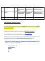
FIJI ELECTRICITY AUTHORITY BIDDING DOCUMENT MR 169/2015 DESIGN, BUILD, SUPPLY, TEST and COMMISSIONING OF THE TAP CHANGER CONTROL UPGRADE FOR 132/33kV TRANSFORMERS AT CUNNINGHAM ROAD AND VUDA NCC SUBSTATION Section 1. Instructions to Bidders 1. Scope of Bid The Fiji Electricity Authority (hereinafter referred to as "the Employer"), wishes to receive bids for full DESIGN, BUILD, SUPPLY, TEST and COMMISSION TAP CHANGER CONTROL UPGRADE FOR 132/33kV TRANSFORMERS AT CUNNINGHAM ROAD AND VUDA NCC SUBSTATION as defined in these bidding documents (hereinafter referred to as "the Works"). The successful bidder will be expected to complete the Works within 12 Months from the date of commencement of the Works. 2. Eligible Bidders This Invitation to Bid is open to bidders who have sound financial background and have previous experience in handling such projects. Bidders shall provide such evidence of their continued eligibility satisfactory to the Employer as the Employer shall reasonably request. Bidders shall not be under a declaration of ineligibility for corrupt or fraudulent. 2. Eligible Materials, Equipment and Services The materials, equipment, and services to be supplied under the Contract shall have their origin from reputable companies from various countries and all expenditures made under the Contract will be limited to such materials, equipment, and services. At the Employer's request, bidders may be required to provide evidence of the origin of materials, equipment, and services. 3. Qualification of the Bidder To be qualified for award of Contract, bidders shall submit proposals regarding: 1. Work methods 2. Work scheduling and 3. resourcing This shall be provided in sufficient detail to confirm the bidder’s capability to complete the works in accordance with the specifications and the time for completion. 4. Cost of Bidding The bidder shall bear all costs associated with the preparation and submission of its bid and the Employer will in no case be responsible or liable for those costs. 5. Site Visit The bidder is advised to visit and examine the Site of Works and its surroundings and obtain for itself on its own responsibility all information that may be necessary for preparing the bid and entering into a contract for the design-build and completion of the Works. The costs of visiting the Site shall be at the bidder's own th expense. The pre-bid meeting is scheduled at 10.00a.m on Wednesday 28 th October at Cunningham Rd Substation, Suva, Fiji and Thursday, 29 October at 132kV Vuda Substation, Lautoka, Fiji. 6. Sealing and The bidder shall seal the original copy of the technical proposal, the original copy of Marking of Bids the price proposal and each copy of the technical proposal and each copy of the price proposal in separate envelopes clearly marking each one as: "ORIGINALPROPOSAL", and “COPY PROPOSAL", etc. as appropriate. The bidder shall seal the original bids and each copy of the bids in an inner and an outer envelope, duly marking the envelopes as "ORIGINAL" and "COPY". The inner and outer envelopes shall be addressed to the Employer at the following address: Tuvitu Delairewa General Manager Corporate Services 2 Marlow Street, Suva, FIJI. Phone: 679 3224 185 Facsimile: 679 331 1882 Email: [email protected] And bear the following identification: • • Bid for: DESIGN, BUILD, SUPPLY, TEST and COMMISSIONING OF THE TAP CHANGER CONTROL UPGRADE FOR 132/33kV TRANSFORMERS AT CUNNINGHAM ROAD AND VUDA NCC SUBSTATION Bid Tender Number: MR 169/2015 th • DO NOT OPEN BEFORE – 26 November, 2015 7. Deadline for Submission of Bids Bids must be received by the Employer at the address specified above no later than th Wednesday, 25 November 1600 hours (Local Fiji Time). 8. Late Bids Any bid received by the Employer after the deadline for submission of bids prescribed in Clause 23 will be rejected and returned unopened to the bidder. 9. Modification and Withdrawal of Bids The bidder may modify or withdraw its bid after bid submission, provided that written notice of the modification or withdrawal is received by the Employer prior to the deadline for submission of bids. The Employer may, at its discretion, extend the deadline for submission of bids by issuing an addendum, in which case all rights and obligations of the Employer and the bidders previously subject to the original deadline will thereafter be subject to the deadlines extended. The bidder's modification or withdrawal notice shall be prepared, sealed, marked and delivered in accordance with the provisions of Clause 22, with the outer and inner envelopes additionally marked "MODIFICATION" or "WITHDRAWAL", as appropriate. A withdrawal notice may also be sent by fax but must be followed by a signed confirmation copy. No bid may be modified by the bidder after the deadline for submission of bids. 10. Employer's Right to Accept any Bid and to Reject any or all Bids Notwithstanding Clause 34, the Employer reserves the right to accept or reject any bid, and to annul the bidding process and reject all bids, at any time prior to award of Contract, without thereby incurring any liability to the affected bidder or bidders or any obligation to inform the affected bidder or bidders of the grounds for the Employer's action. 11. Notification of Award Prior to expiration of the period of bid validity prescribed by the Employer, the Employer will notify the successful bidder by fax, confirmed by registered letter, that its bid has been accepted. This letter (hereinafter and in the Conditions of Contract called the "Letter of Acceptance") shall name the sum which the Employer will pay the Contractor in consideration of the execution, completion and maintenance of the Works by the Contractor as prescribed by the Contract (hereinafter and in the Conditions of Contract called "the Contract Price"). The notification of award will constitute the formation of the Contract. Upon the furnishing by the successful bidder of a performance security, the Employer will promptly notify the other bidders that their bids have been unsuccessful 12. Signing of Contract Agreement At the same time that he notifies the successful bidder that its bid has been accepted, the Employer will send the bidder the Form of Contract Agreement provided in the bidding documents, incorporating all agreements between the parties. Within 7 days of receipt of the Form of Agreement, the successful bidder shall sign the Form and return it to the Employer. 13. Corruptor Fraudule nt Practices The Employer requires that the Contractor observe the highest standard of ethics during the procurement and execution of such contracts. In Pursuance of this policy, the Employer: (a) defines, for the purposes of this provision, the terms set forth below as follows: (i)"corrupt practice" means behavior on the part of officials in the public or private sectors by which they improperly and unlawfully enrich themselves and/or those close to them, or induce others to do so, by misusing the position in which they are placed, and it includes the offering, giving, receiving or soliciting of anything of value to influence the action of any such official in the procurement process or in contract execution; and (ii) "fraudulent practice" means a misrepresentation of facts in order to influence a procurement process or the execution of a contract to the detriment of the Employer, and includes collusive practice among bidders (prior to or after bid submission) designed to establish bid prices at artificial non-competitive levels and to deprive the Employer of the benefits of free and open competition; (b) will reject a proposal for award if it determines that the bidder recommended for award has engaged in corrupt or fraudulent practices in competing for the contract in question; Furthermore, bidders shall be aware of the provision stated in Sub-Clause 1.16 and Sub-Clause 15.5 of the Conditions of Contract, Part II - Conditions of Particular Application. Contents Scope of Work ............................................................................................................................................... 7 1. General Description .......................................................................................................................... 7 2. General Scope ................................................................................................................................... 7 3. Tap Changer Controller ..................................................................................................................... 7 4. 3.1. Cunningham Substation ............................................................................................................ 7 3.2. Vuda Substation ........................................................................................................................ 7 Tap changer Control Panel ................................................................................................................ 8 4.1. Construction .............................................................................................................................. 8 4.2. Wiring ........................................................................................................................................ 9 4.3. Use of Lugs for Wiring ............................................................................................................... 9 4.4. Terminal Blocks ......................................................................................................................... 9 4.5. Earthing ................................................................................................................................... 10 4.6. Labels ...................................................................................................................................... 10 4.7. Switches .................................................................................................................................. 10 4.8. Indication ................................................................................................................................ 11 4.9. Panel Protection...................................................................................................................... 11 4.10. Panel Structure.................................................................................................................... 11 5. Training ........................................................................................................................................... 11 6. User manual for operations ............................................................................................................ 11 7. Drawings ......................................................................................................................................... 11 8. Automation Design and Compatibility ............................................................................................ 12 9. Outages ........................................................................................................................................... 12 Scope of Work 1. General Description This specification covers the technical requirements for the upgrading of the existing Tap Changer Controllers at Cunningham Substation and Vuda NCC Substation for the 132/33kV Transformers, each substation has two transformers, therefore a total of four (4) transformer tap changer controllers are required. New tap changer controllers have to be installed complete with all accessories for efficient and trouble free operation. The required equipment shall be manufactured as per the specifications listed in this specification document. In case of any deviation from the mentioned, the vendor shall bring into notice the same along with its offer. In absence of such deviation, it will be presumes that equipment offered is exactly similar to the specification. The bidder(s) will be evaluated based on the features, quality, technicality and durability of the design. 2. General Scope It is the complete responsibility of the bidder to: 2.1. 2.2. 2.3. 2.4. 2.5. 2.6. 2.7. Design Build Transport, Supply and Deliver Insurance to Site Install and Test Provide Training And Commission the Tap Changer Control Unit 3. Tap Changer Controller The preferred tap changer controller shall be of Brand – Maschinenfabrik Reinhausen (MR) – TAPCON ISM or an alternative of brand DRMCC. Each transformer shall have one (1) controller of its own. The controllers shall be custom programmed with respect to the details provided below. 3.1. Cunningham Substation 3.1.1.Number of Transformers - 2 3.1.2.Voltage Rating – 132/33kV 3.1.3.Power Rating – 40/60MVA 3.1.4.Number of taps – 19 3.1.5.Tap changer Drive Mechanism Motor - 3 Phase, 415V 3.1.6.Tap Position Detection Provision – 3.1.7.Parallel Operations – Both controllers shall be programmed to operate as Master/ Follower 3.2. Vuda Substation 3.2.1.Number of Transformers - 2 3.2.2.Voltage Rating – 132/33kV 3.2.3.Power Rating – 30MVA 3.2.4.Number of taps – 19 3.2.5.Tap changer Drive Mechanism Motor - 3 Phase, 415V 3.2.6.Tap Position Detection Provision – 3.2.7.Parallel Operations – Both controllers shall be programmed to operate as Master/ Follower 3.3. The controller shall: 3.3.1.Communicate via SCADA-DNP3 and IEC61850 Protocol 3.3.2.Communicate through Fiber Optics 3.3.3.The controller shall be programmed to interpret the Remote/Manual/Auto function from the switch. (This is further explained below under “Switches”). 3.3.4.The controller shall be programmed to interpret the Raise/Lower function from the switch to Raise or Lower the Tap Position. (This is further explained below under “Switches”). 3.3.5.Be programmed to operate the Master/Slave Protocol. There shall be a hard wired selector switch whereby it shall determine which controller shall be put into Master and Slave. 3.3.6.Display the Tap Number, Tapped Voltage and any other necessary details. 3.3.7.The controller itself shall be programmed to rise and lower the tap positions with the use of switches. 3.4. The controller shall be able to interpret the manual inputs/hardwired switch inputs. These are: 3.4.1.A selector switch to determine the controller operation to be Manual/Remote/Auto. 3.4.2.A selector switch to determine each controller to be either Master or Follower. 3.4.3.A push button under each controller to raise or lower the tap position. 4. Tap changer Control Panel 4.1. Construction 4.1.1.The panel shall be metal enclosed, free standing type suitable for indoor installation. The panel shall be dust and vermin proof and the enclosure shall provide a degree of protection not less than IP-65. The height of the panel shall not be more than 2200mm and the depth shall not exceed 800mm. The panel shall be sized large enough width wise such that two tap changer controllers can be placed side by side. Also, the switches, indications and meters shall be properly spaced and correctly placed to avoid confusion. 4.1.2.The tap changer controllers shall be flush mounted on the face of the panel, side by side, with all the necessary control underneath the controllers. 4.1.3.The panel shall be fabricated and properly supported using C-Channel or Angle Line metal, so the frame does not deteriorate from its shape in due time. The whole panel shall be mounted on a base frame made out of hot dip galvanized structure. Joints of any kind in sheet shall be seam welded, all welding slag grounded off and welding pit wiped smooth with plumber metal. All panels and covers shall be properly fitted and made square with frames. All the holes in the panels shall be correctly positioned. Self-threading screws shall NOT be used in any construction works. The metal sheet, for the construction of the panel, shall be of at least 1.5mm of thickness. 4.1.4.Each cable chamber shall have cable entry from the bottom, suitable removable gland plates, of 6mm Aluminum, shall be provided for this purpose. The cable chamber shall be provided with suitable supporting arrangement between gland plates and terminals, in the middle. 4.1.5. A horizontal wire-way with screwed cover shall be provided at the top/ bottom to take inter-connecting control wiring. Separate and adequate compartments shall be provided for accommodating instruments, indicating lamps, control fuses etc. These shall be accessible for testing and maintenance without any danger of an electrical hazard. 4.1.6.All similar materials and removable parts of the panel shall be interchangeable. The panel shall be filled with the same family of switches for various ratings with a view to ensure uniformity of design, maintenance and replacements. 4.1.7.Painting shall be done by surface coating comprising pre-treatment and curing. The surfaces shall be chemically de-rusted and degreased prior to painting. White colored paint shall be applied as the finishing paint. 4.2. Wiring 4.2.1.It shall be the responsibility of the bidder to do the control wiring from controller panel to the respective input/output points of the transformer 4.2.2.It shall be the responsibility of the bidder to do all the internal control wirings of the Tap changer control panel. Supply of all types of the cables (control, serial etc.) shall be the bidder’s responsibility. 4.2.3.Panel shall be supplied with all wiring comprising of PVC insulated 1 .1 KV grade, multistrand flexible copper conductor of 2.5 Sq.mm cross section. 4.2.4.Wiring associated with a particular phase shall be the color of that phase. Red/ Yellow, or Blue. Wiring associated with earthing shall be with green color insulation and for neutral it shall be with black color insulation 4.2.5.Wiring shall be neatly laid and run on insulated cleats of limited compression type insulated straps. 4.2.6.All cables shall have crimped terminations and shall be identified by means of glossy plastic ferrules at both ends, showing the wire number as indicated in the schematic diagrams. The ferrules shall be indelibly marked. 4.2.7.The cable laid between the panel and the transformer shall be done with armored multicore cables 4.2.8.Wiring to items mounted on hinged doors or wiring that is subject to movement shall run in helical binding. The binding shall be securely anchored at both ends and sufficient slack provided to prevent any strain being imposed of wiring. 4.3. Use of Lugs for Wiring 4.3.1.2.5mm Ring Lugs shall be used for wiring to the meters, switches, indicators and controllers. 4.3.2.All lugs shall be provided for terminations with 10% spare. 4.3.3.Lugs shall be insulated type. 4.4. Terminal Blocks 4.4.1.Terminal blocks shall preferably be grouped according to circuit functions and each terminal block group shall have at least 10% spare terminals. Terminal blocks for control circuit shall be greater than 650V grade with contact ratings not less than 10A. 4.4.2. Not more than two wires shall be connected to any terminal block. All terminal blocks shall be mounted on a rail and shall be at a place easy to access. 4.4.3.Clip-on terminals of at least 650 V grade shall be provided for the cables up to 35 mm².Preferable terminal blocks which shall be used are DIN-rail Clip-On Screw Connection, product of Klemsan. 4.5. Earthing 4.5.1.All the metal parts of all equipment supplied within the panel (including doors and gland plates) other than those forming part of all electric circuit, shall be connected by means of two independent earth conductors to copper earth bar. 4.5.2.The Panel shall be provided with two brass earthing stud terminals, with suitable nuts, washers etc. for connection to ground bus. 4.5.3.There shall be a single Cupper Earth Bar in the panel common for all Earth Points. This shall be size of 10mm thickness, 30mm of width and a length of at least 500mm. 4.6. Labels 4.6.1.Labels shall be provided to describe the duty of or otherwise identify every Instrument, or other item of equipment mounted internally and externally. Switch positions shall be fully identified. Wording shall be clear, concise and unambiguous 4.6.2.Each label shall be permanently secured to the panel surface below the item to which it refers. 4.6.3.The labels shall be engraved plastic (4 mm thick) with bold white letters in black background. 4.7. Switches 4.7.1.There shall be individual switch for: 4.7.1.1. The control of Remote/Local/Automatic selection. This shall be a Three (3) position rotary cam changeover switch. Each selection have its own control. The: 4.7.1.1.1. Remote – this selection shall put control the National Control Center (NCC) on control over the Tap Changer Control, whereby, NCC shall be able to Raise or Lower the Tap position via SCADA Control remotely. 4.7.1.1.2. Local – this selection shall put the hard wired switches on control. This includes the Raise and Lower of Tap Position and putting each controller to either Master or Follower position or both to Independent. 4.7.1.1.3. Automatic Control – this selection shall place the Tap Controller to fully control of Tap Changer according to the load on the transformer. 4.7.1.2. The control of Master/Follower/Independent. This shall be a Three (3) position rotary cam changeover switch. Each selection have its own control. For this operation, any one of the controller shall be Master and the other shall be Follower or both can be Independent. The: 4.7.1.2.1. Master – this selection shall put the controller in charge of the Tap Change. 4.7.1.2.2. Follower- this selection shall work in accordance to the Master selection. Whereas, if the Master Controller changes the Tap Position of its Transformer, the Follower shall change to the same tap as of the Master. 4.7.1.2.3. Independent – this selection shall apply to both the transformers at the same time to make their Tap Change according to the load on each transformer. 4.7.2.There shall be individual switch for each Transformer Controller for manual Tap Change locally. It shall be of Spring Return Push Button, whereas the Green colored button shall be used to raise the tap position and the Red colored button shall be used to lower the tap position. 4.8. Indication 4.8.1.There shall be 1.5Watt Orange LED Lights, for indication of Tap Position for each Transformer. Each Transformer has 19 Taps in total, thus nineteen (19) indications. 4.8.2.There shall be 1.5Watt Red LED Light, to indicate the Tap Change Process. This shall glow till the process is going on and turn off as the Tap Position changes. 4.9. Panel Protection 4.9.1.The main AC and DC incoming wires shall have appropriate MCB’s. The devices on the panel shall also each have an appropriate MCB each. 4.9.2.There shall be an earth bar mounted at the bottom of the panel which shall only connect the earthing of all the required devices in this panel. 4.9.3.All front mounted as well as internally mounted items including MCBs shall be provided with individual identification labels. Labels shall be mounted directly below the respective equipment and shall clearly indicate the equipment designation. Labeling shall be on aluminum-anodized plates of 1mm thickness, letters are to be properly engraved. 4.10. Panel Structure There shall be provision for each cable chamber, where it shall have cable entry from both top and bottom, suitable removable gland plates shall be provided for this purpose. The cable chamber shall be provided with suitable supporting arrangement between gland plate and terminals, in the middle. 5. Training The bidder shall provide rigorous hands-on and theoretical training to the Engineers and technicians on operations, troubleshooting and maintenance of the Tap changer controller unit. 6. User manual for operations The bidder shall provide a comprehensive user manual, which has complete instructions of operating the Tap Changer Control Unit. The user manual shall be in simple straight forward English and shall be unambiguous. 7. Drawings The bidder shall also provide ALL the single line drawings of the controls wiring done inside the panels and the control wirings done outside the panels i.e. Transformer – panel etc. 8. Automation Design and Compatibility The IEC 68150 (Design of Electrical Substation Automation) standard and DNP 3.0 Protocol shall be used to design the automation systems. The system shall be able to operate in both; however, the system shall be taken over by DNP 3.0 protocol. All hardware in the designs shall be compatible to these protocols. 9. Outages The bidder shall propose the number of outages required to complete the entire cutover. One outage shall not be more than ten (10) hours of duration. Also, the outages can only take place on a Sunday, excluding any festival celebrations namely Easter, Fiji Day, Diwali and Christmas etc. Criteria for Evaluation Weighting Score Range 10 - 8 7-4 3-0 1 Manufacturer’s years of experience in production 10.00 Manufacturer has more than 30 years’ experience Manufacturer has less than 30 years’ experience Manufacturer has less than 10 years’ experience 2 Bidders experience in Similar projects – Design, Build, Supply and Install 10.00 Company has done more than 50 projects of similar nature Company has done 20 - 50 projects of similar nature Company has done less than 20 projects of similar nature 3 Number of years the offered model has been in production and in the market 5.00 Model has been in the market for more than 20 years Model has been in the market for 15 – 20 years Model has been in the market for 10 – 15 years 4 Number of years of experience of key personnel to be involved in project 5.00 More than 10 years for most of the key personnel Less than 10 years for most of the key personnel Less than 5 years for most of the key personnel 5 Manufacturer’s Warranty on Tap changer Controls 5.00 More than 4 years 2 – 4 years Less than 1 year 6 Type test reports on tap changer control units 5.00 Results meet and exceed the requirements as per IEC standards Results do not meet minimum specifications Type test reports not submitted or not as per IEC standards 7 Conformance to acceptable values for routine tests as specified in tender 10.00 Submits evidence that the system will conform &exceed requirements Submits evidence that system will conform to most requirements No evidence of conformance to test requirements 8 Comprehensiveness of proposed design 10.00 All the design details are addressed as that would be expected in an ideal proposal. Relevant design details are addressed in terms of design as that compared to an ideal proposal. Extent of consideration placed into design is significantly less than that expected in a reasonable proposal. Most of the items stated in specifications are not met. 9 Tap Changer Control Panel Evaluation 10.00 Meets all the technical requirements as in the specification. All technical details match with design requirements Meets only the basic requirements of the specification. Proposed technical data is acceptable but does not match with specification Meets only the mandatory requirements of the specification 10 Maintenance Requirements for the tap changer control Unit 5.00 Needs maintenance every 5 years or more Needs Maintenance every 3- 5 years Needs Maintenance every 1 - 2 year 11 Job Safety Requirements 5.00 Meets and exceeds the safety requirements Meets most of the safety requirements Does not meet the level of safety required 12 Innovation in Design 5.00 High degree of innovation incorporated into design Evidence of some innovation incorporated into design No evidence showing any innovation in design 13 Installation of new panel and replacement of existing panel 5.00 Will require minimal tools and equipment from FEA for installation Will require some tools and equipment from FEA for installation Will require all tools and equipment from FEA for installation 14 Delivery period and timeline 5.00 Delivery period is within 18 - 24 weeks and installation is within 2 3 weeks Delivery period is within 24 - 28 weeks and installation is within 3 - 4 weeks Delivery period would exceed 28 weeks and installation would also exceed 4 weeks 15 Quality Control 5.00 Manufacturer has quality system in accordance with international standards and produced evidence of regular third party audits Manufacturer appears to have a quality system in place. Manufacturer has a record of providing reasonable quality material but provides no evidence of a quality system Total 100% Tender Submission - Instruction to bidders It is mandatory for Bidders to upload a copy of their bid in the TENDER LINK Electronic Tender Box no later than 4:00pm, on Wednesday 25th November, 2015. To register your interest and tender a response, view 'Current Tenders' at: https://www.tenderlink.com/fea For further information contact The Secretary Tender Committee, by e-mail [email protected] In additional, hard copies of the tender, one original and one copy must be deposited in the tender box located at the FEA Head Office, 2 Marlow Street, Suva, Fiji no later than 4:00pm, on Wednesday 25th November, 2015- Addressed as Tender – MR 169/2015 – Design, Build, Supply, Test and Commissioning of the Tap Changer Control Upgrade for 132/33kV Transformers at Cunningham Road and Vuda NCC Substation The Secretary Tender Committee Fiji Electricity Authority Head Office Suva Fiji Hard copies of the Tender bid will also be accepted after the closing date and time provided a soft copy is uploaded in the e-Tender Box and it is dispatched before the closing date and time. Tenders received after 4:00pm on the closing date of Wednesday 25th November, 2015 will not be considered. Lowest bid will not necessarily be accepted as successful bid. It is the responsibility of the bidder to pay courier chargers and all other cost associated with the delivery of the hard copy of the Tender submission. TENDER SUBMISSION CHECK LIST The Bidders must ensure that the details and documentation mention below must submitted as part of their tender Bid Tender Number _________________ Tender Name_______________________________________________________________ 1. Full Company Name:_____________________________________________________ (Attach copy of Registration Certificate) 2. Director/Owner(s):________________________________________________________ 3. Postal Address:___________________________________________________________ 4. Phone Contact:___________________________________________________________ 5. Fax Number:_____________________________________________________________ 6. Email address:___________________________________________________________ 7. Office Location:___________________________________________________________ 8. TIN Number:____________________________________________________________ (Attach copy of the VAT Registration Certificate – Local Bidders Only) 9. Company Registration Number:______________________________________________ (Attach copy of the Business License) 10. FNPF Employer Registration Number:_________________________________________ (For Local Bidders only) 11. Contact Person:____________________________________________ I declare that all the above information is correct.