1
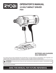
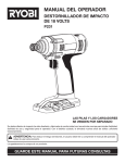
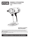
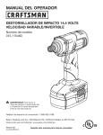
DS-50/DS-75/DS-100 MINI ROLL-UP DOORS INSTALLATION INSTRUCTIONS IMPORTANT NOTICE !! Read the enclosed instructions carefully before attempting to install this door. Pay close attention to all warnings and important safety notices. This manual MUST be attached to the wall in close proximity of the door. ©Copyright 2004 Wayne-Dalton P/N 300847, DOC #101-0117 REV 03 IMPORTANT SAFETY NOTICES Read the enclosed instructions carefully before attempting installation. If there are any questions about any of the procedures, do not perform the work. Instead, have a trained door technician do the installation or repairs. 1. Operate the door ONLY when it is properly adjusted and free of all obstructions. 2. The door is constantly under EXTREME SPRING TENSION. Repairs, adjustments, installation and removal, ESPECIALLY of SPRINGS AND RELATED PARTS, are dangerous. Such work should be performed ONLY by trained door technicians. 3. DO NOT PERMIT children to play with the door. Children could get caught between the door and the floor causing severe injury or death. 4. Avoid standing in the open doorway or walking through the doorway while the door is moving. One could get caught between the door and the floor causing severe injury or death. 5. Should the door become hard to operate or completely inoperative, it is recommended that a trained door technician correct the problem to prevent possible injuries or door damage. 6. Avoid installing the door on windy days. The door could fall causing personal injury or door damage. 7. To prevent injuries due to loose components, at least monthly check all bolted connections to make sure they are secure. 8. To prevent injuries, never place hands or fingers between the curtain and the guides while the door is being operated. 9. This manual is not intended to provide "take-down" instructions for existing doors. Consult your local door agency if this is required, before new doors are to be installed. 10. Thoroughly familiarize yourself with the building codes in your region before initiating work. 11. Wear the proper protective safety gear at all times when installing, adjusting, and/or repairing doors. 12. Use a 2-person (or larger) crew for installing, adjusting, and/or repairing larger doors. 13. Definitions of key words used in this manual are as follows: This is the safety alert symbol. It is used to alert you to potential personal injury hazards. Obey all safety messages that follow this symbol to avoid possible injury or death. WARNING WARNING indicates a potential hazardous situation which, if not avoided, could result in serious injury or death. CAUTION CAUTION indicates a potentially hazardous situation which, if not avoided, may result in minor or moderate injury. CAUTION CAUTION used without the safety alert symbol indicates a potentially hazardous situation which, if not avoided, may result in property damage. IMPORTANT! IMPORTANT! indicates a required step for safe and proper door operation. NOTE: HINT: 2 NOTE: indicates information assuring proper installation of the door. HINT: indicates a suggested step to simplify installation based on experience. INTRODUCTION This manual's main function is to assist the installer in correctly installing the doors to ensure safe operation. Compliance with building codes, enforced in your area, is required. All Wayne-Dalton DS-50, DS-75, and DS-100 Mini Roll-Up Doors follow these general instructions. Additional installation information for the specific door shipped is found with the packing slip and on supplementary drawings. There are also bolt and small sealed parts bags with accessory lists, describing proper application. PREPARATION Read the installation instructions thoroughly to become familiar with the names of the various components and their relation to each other. It is necessary for the installer to determine the following: Type of jamb material (wood, masonry, or steel) on which the door guides will be mounted. The dimensions for the opening width, opening height, headroom, and side room. Type of support brackets provided (bearing bracket or Tension-Pro™ bracket). MATERIAL Inspect your door for possible damage or shortage of parts. Immediately report any shortages to your door supplier, or transit related damage claims to your freight carrier. CLEARANCES Compare the door opening dimensions and available clearances against the dimensions listed on the packing slip, taking special note of the opening width and height. TOOLS Commonly used tools for proper installation are: Electric drill with 3/8" or 1/2" chuck with nut driver and drill bits. Masonry drill or impact hammer and bits. Ladders and/or scaffolding. Hammer and pliers. Large Pipe Wrench (if Tension-Pro bracket). Center punch and Screwdrivers. Wrenches, vise grips, and C-clamps. Tape measure and a water level. FASTENER TABLE Jamb Condition Wood Masonry Steel Bracket Fasteners 5/16 x 1-1/2” Lag Screw 5/16 x 1-1/2” Wedge Anchor 1/4 x 3/4” Self Drilling Screw Guide Fasteners 5/16 x 1-1/2” Lag Screw 1/4 x 1-3/4” Tapcon 1/4 x 3/4” Self Drilling Screw 3 STEP 1 UNPACKING DOORS Before removing the door from any packaging, inspect the packaging for visible signs of damage. If damage is noted, file a freight claim with the freight company immediately. Remove the door from the packaging. IMPORTANT! Do not cut tape that holds door in a roll. You will be told in STEP #7 when to cut the tape. No guarantee will be given by Wayne-Dalton if the door is not installed as instructed. Please review all instructions thoroughly before starting installation. For proper operation, follow these instructions step by step. NOTE: Right and Left Hand is determined by facing the door opening, on the coil side. STEP 2 CHECKING THE DOOR OPENING Verify that dimensions W and H (see below) match those recorded on the door packing slip. Consult the factory if the actual opening width is greater than that shown on the packing slip by more than 1-1/2 inches. Check to make certain that the door opening is square and plum and that the floor is level. Check to be certain there is sufficient clearance from the opening to the ceiling and the sidewalls (see Required Clearances below). OPENING HEIGHT HEADROOM (A) SIDE ROOM (B) UP TO 6’8” HIGH 13” 4” FROM 6’8-1/4” TO 8’ HIGH 14” 4” OVER 8’ HIGH 16” 4” REQUIRED CLEARANCES - MINIMUM INDICATED 4 STEP 3 INSTALLING GUIDES Position the left hand guide 3/8” from the edge of the left hand jamb and loosely clamp in place. Using a level, adjust the guide so that it is plumb and tighten the clamp. Measure the exact curtain width of the door and add 7/8” to obtain the inside of guide to inside of guide measurement. Use this measurement to locate the right hand guide. Loosely clamp the right hand guide to the jamb. Plumb the guide and tighten the clamp. Using a string and level, ensure that the tips of the left and right hand guides are level to each other. Shim guides as needed. Double check the inside of guide to inside of guide measurement at top, middle, and bottom to ensure that the guides are plumb and parallel. Fasten both guides to the jambs using the fasteners provided (See Fastener Table in the front of this manual). IMPORTANT! Inside of guide to inside of guide measurement must be held to ensure proper door operation. IMPORTANT! Use of any other fasteners than those provided must be approved by Wayne-Dalton and cannot be of lesser diameter or grade. STEP 4 INSTALLING BRACKETS Install the brackets to the outside of the guides (away from the opening) using two 1/4-20 x 9/16” track bolts in the two holes at the top of the guides, as shown. Loosely install the 1/4-20 flange nuts on the bolts to hold the brackets in place. Check that the brackets are straight and square with one another, shimming if necessary, and fasten the brackets to the wall using the fasteners provided (See Fastener Table in the front of this manual). Tighten the flange nuts on each bracket. Install the bottom bar stops to the guides as shown using 1/4-20 x 5/8” carriage bolts and flange nuts. Leave the fasteners loose to allow the bottom bar stops to pivot out of the way of the bottom bar angle when the curtain will be pulled into the guides. You will be instructed to tighten the bottom bar stop fasteners in STEP #7. 5 STEP 5 LIFTING THE CURTAIN ASSEMBLY WARNING Curtain assembly is heavy. Allowing curtain assembly to fall while lifting, could result in severe or fatal injury. WARNING To avoid severe or fatal injury, never walk, stand, or work below curtain assembly before it is secured to support brackets. The left hand end of the curtain assembly (when installed) will be the end with the spring. Lift the curtain assembly up to the brackets and insert the left hand axle end into the large hole in the left hand bracket. Be sure that the axle collar rests against the bracket. While continuing to support the curtain assembly, insert the right hand axle end into the right hand bracket in the same manner. It may be necessary to gently pry the right hand bracket out to allow clearance for the curtain assembly axle end. Secure the curtain assembly in position by installing the cotter pins through the holes in each axle end. Once installed, bend the ends of both cotter pins to secure in place. IMPORTANT! STEP 6 If door is equipped with a Tension-Pro™ bracket, see STEP #12 for assembly instructions. ATTACHING SPRING Rotate curtain assembly so that the bottom bar is at the top of the curtain roll. While keeping the curtain from rotating, carefully stretch the spring end to the bracket to determine the bracket hole nearest to the loop in the spring end. Position the 5/16-18 x 1” hex head bolt and flat washer in the spring loop and stretch the spring to insert the bolt into the previously determined bracket hole. Loosely install the lock washer and nut on the outside of the bracket to hold the spring stretch. Rotate the spring until it is centered on the bracket and securely tighten the spring attachment bolt. (Axle Pin installed in step #5 omitted from view for clarity) HINT: 6 For an easier way of installing the spring attachment bolt, if the installation permits, use vice grips to temporarily secure spring loop to bracket. STEP 7 PRE-TENSIONING THE DOOR SPRING WARNING Spring tension can cause curtain assembly to rotate rapidly, possibly resulting in severe or fatal injury. To prevent such injury, securely hold curtain assembly to prevent rotating. Starting with the bottom bar at the top of the curtain roll, apply two complete turns of pre-tension to the spring by rotating the curtain roll in the direction shown. The amount of tension required may vary slightly. Final adjustment, if necessary, will be made in STEP #9. Cut the tape that holds the curtain in a roll and gently pull the curtain down into the guides on both sides until the bottom bar is below the bottom bar stops. Do not pry on the bottom bar stops to get bottom bar past the stops. Instead, loosen fasteners until bottom bar angle easily clears stops. If the door has a tendency to close, secure it in position using clamps. If the door has a tendency to rise, secure it in position using a wood prop. WARNING Securely hold curtain assembly until bottom bar stop fasteners have been tightened. If not securely held, curtain could rotate, possibly causing severe or fatal injury. With the door kept from moving, tighten the bottom bar stop fasteners on both guides. Remove clamps or wood props. STEP 8 LUBRICATING AND ADJUSTING THE GUIDES Lubricate the insides of guides with weather resistant lubricating spray. Move the door up and down to check for proper operation. Adjust the guides if necessary to allow for proper clearance and operation. HINT: If door is difficult to move up or down due to spring imbalance, continue on to STEP #9 and return to STEP #8 once springs are properly adjusted. 7 STEP 9 CHECKING AND ADJUSTING SPRING BALANCE WARNING Spring tension can cause curtain assembly to rotate rapidly, possibly resulting in severe or fatal injury. To prevent such injury, securely hold curtain assembly to prevent rotating. Move the door up and down to check for proper spring tension. If the door lowers easily and raises hard, more spring tension is required. If the door lowers hard and raises easily, less spring tension is required. If a tension adjustment is necessary, secure the door in position and remove the bottom bar stops. Carefully roll the curtain all the way up without letting go of the bottom bar. Tie a rope around the curtain roll and slowly rotate the curtain roll in the opposite direction as tension was applied until spring is neutral. Change the location of the spring attachment bolt in the required direction as shown. Repeat STEPS 6, 7, 8, and 9. See STEP #12 for Tension-Pro™ bracket spring tension adjustment. WARNING STEP 10 Securely hold curtain assembly until bottom bar stop fasteners have been tightened. If not securely held, curtain could rotate, possibly causing severe or fatal injury. INSTALLING LIFT HANDLE, STOP CLIPS AND OPTIONAL SLIDE BOLT LOCKS Install a lift handle in the center of the bottom bar using 1/4-20 x 5/8” carriage bolts and flange nuts, placed so the nut is on the coil side, or inside of door as shown. If the opening width is greater than 5 foot and the door does not have slide bolt locks, install a second lift handle on the right hand side of the bottom bar (outside looking in). Install 1/4-20 x 5/8” carriage bolts and flange nuts in all remaining bottom bar holes. (2) ‘Z’ stop-clips (4) ¼ - 20 flange nuts (4) ¼ - 20 carriage bolts 8 I: DS-75 Mini ‘Z’ Stop-Clip Attachment: For DS-75 mini doors, install the ‘Z’ stop-clip as shown on the right. Since the stop-clip has a retaining tab on top, it only requires one bolt to secure it to the bottom bar. Repeat assembly procedure for both sides. II: DS-50 & 100 ‘C’ Stop-Clip Attachment: For doors with an aluminum bottom bar, a ‘C’ stop-clip will need to be installed. Only one bolt is required to secure the stop-clip to the bottom bar when attaching a lift handle on that side. Repeat assembly procedure for both sides. (4) ¼ - 20 carriage bolts (4) ¼ - 20 flange nuts (2) ‘C’ stop-clips (4) ¼ - 20 carriage bolts (4) ¼ - 20 flange nuts *pre-attached to btm bar III: ‘C’ Stop-Clip w/ Inside Slide Bolt Attachment: (2) ‘C’ stop-clips (2) inside slide (4) ¼ - 20 flange WARNING STEP 11 Install slide bolt locks, if provided, as shown. The bottom bar will have (4) carriage bolts & flange nuts preattached. Verify that the flat sides of the nuts are horizontal to the bottom bar. This ensures smooth operation of the slide bolt. Place the slide bolt lock so that the slot rides on the flange nuts. Then, add the stopclip and attach, using the flanged nuts. Repeat assembly procedure for both sides. Failure to properly install stop-clips to the bottom of the door may result in serious injury or death INSTALLING OPTIONAL TOP DRAFT STOP Close the door and secure it in the down position. Use a pencil to mark the door panel corrugation that is parallel with the bottom of the header/lintel from the outside of the opening. If this corrugation protrudes below the header, mark the one just above. Open the door until the marked corrugation is accessible. Stretch the top draft stop across the door and attach it to the curtain on the marked corrugation with the self-drilling screws provided, locating the screws on 12” centers. Trim the top draft stop to clear the guides if required. When the door is closed, the draft-stop should seal on the header. NOTE: Top draft stop may not seal on the header if not installed on a corrugation as shown. 9 STEP 12 INSTALLING THE OPTIONAL TENSION-PRO SPRING ADJUSTMENT BRACKET STEP #12a: Install the Tension-Pro™ bracket on the left hand side of the curtain assembly per STEP #4 & #5 in this manual. Insert cotter pin through hole in the axle end. Do not use large washer (shown in step #5) on the Tension-Pro™ bracket side axle end. Bend the ends of the cotter pin to secure in position. STEP #12b: Stretch and attach spring end to the spring holder plate of the Tension-Pro™ bracket. Tighten the flange nylon lock hex nut to keep spring in place. STEP #12c: Using a pipe wrench, rotate the large nut clockwise 2 turns to pre-tension the spring. Then, lubricate and adjust guides. STEP #12d: Test door operation to determine if spring balance requires adjustment. Adjust tension as needed per the following instructions. WARNING WARNING 10 Spring tension can cause severe or fatal injury. To avoid injury, repairs/ adjustments must be made by a trained door technician. Spring tension increases as door closes. To avoid possible Injury, door must be fully open when adjusting spring tension. WARNING Pipe wrench interference can prevent pawl from engaging with ratchet gear. Always adjust tension one “CLICK” (gear tooth) at a time. Reposition wrench for each adjustment. Failure of pawl to engage with ratchet gear can cause severe or fatal injury. WARNING Contact with rapidly rotating ratchet gear can cause severe or fatal injury. If wrench slips when decreasing tension, release pawl immediately to avoid injury. Do not secure pawl in the disengaged position. To Increase Spring Tension: Move the door to the fully open position and place clamps on the guides to prevent door from closing. Using a large pipe wrench, grip the tensioning hex plate and rotate the ratchet gear assembly in the direction indicated above until an audible “CLICK” is heard (one gear tooth). Operate the door to determine if the spring tension increase was sufficient. Repeat spring tension increase procedure until door is properly balanced. To Decrease Spring Tension: Move the door to the fully open position and place clamps on the guides to prevent door from closing. Using a large pipe wrench, grip the tensioning hex plate and remove the spring tension force from the pawl. Grip the pawl retention screw and pull the pawl in the direction indicated above to keep it disengaged. Slowly release spring tension held with the pipe wrench, allowing the ratchet gear to begin to rotate in the direction indicated above. The spring tension will rotate the gear in the proper direction. Once the stop face of the previously engaged tooth has passed the tip of the pawl, release the pawl to allow it to engage the next tooth. Operate the door to determine if the spring tension decrease was sufficient. Repeat spring tension decrease procedure until door is properly balanced. STEP #12e: Once spring tension has been adjusted and the door is properly balanced, lock the pawl in position by tightening the pawl retention screw until it penetrates the bracket. Test that the pawl is locked in position by attempting to add one(1) “CLICK” of tension. If properly locked, the ratchet gear will not be able to rotate. If ratchet gear rotates, adjust tension back to previous position, verify that the pawl retention screw is lined up with the hole in the bracket, and tighten the pawl retention screw. Return to STEP #10 in this manual and continue with the door installation. If pawl retention screw does not penetrate hole in Tension- Pro bracket, spring tension could be released during door operation, allowing door to close rapidly, possibly causing severe or fatal injury. WARNING WARNING The pawl retention screw, if not properly aligned with the hole in the Tension-Pro bracket, can cause pawl to disengage. To prevent severe or fatal injury from unexpected release of spring tension, do not drive retention screw with screw gun. WARNING To prevent severe or fatal injury, keep fingers, hands, arms and loose clothing away from all moving mechanisms. 11 Roll-Up Sheet Door LIMITED WARRANTY Wayne-Dalton P.O. Box 67- Mt. Hope, Ohio 44660 The Manufacturer warrants the ROLL-UP SHEET DOOR and hardware fittings for a period of ONE YEAR from the time of delivery against any defects in workmanship or material. Manufacturer shall, upon notification, correct such nonconformity at its option, by repairing or replacing any defective part or parts. NO EMPLOYEE, DISTRIBUTOR, OR REPRESENTATIVE IS AUTHORIZED TO CHANGE THE FOREGOING WARRANTIES IN ANY WAY OR GRANT ANY OTHER WARRANTY ON BEHALF OF MANUFACTURER. The Manufacturer shall not be responsible for any damage resulting to or caused by its products by reason of installation, improper storage, unauthorized service, alteration of products, neglect or abuse, or attempt to use the products for other than the customary usage or for their intended purposes. The ROLL-UP SHEET DOOR warranty becomes null and void if other than Manufacturer’s specified holes are drilled. The above warranty does not cover wear or any damage beyond Manufacturer’s control or replacement labor. THIS WARRANTY COVERS A COMMERCIAL PRODUCT, THE FOREGOING WARRANTIES ARE IN LIEU OF ALL OTHER WARRANTIES AND NO REPRESENTATIONS, GUARANTEES, OR WARRANTIES, EXPRESSED OR IMPLIED, (INCLUDING, BUT NOT LIMITED TO, THE WARRANTY OF MERCHANTABILITY OR FITNESS FOR PARTICULAR PURPOSE), ARE MADE BY MANUFACTURER IN CONNECTION WITH MANUFACTURE OR SALE OF ITS PRODUCTS. Claims for defects in material and workmanship covered by this warranty shall be made in writing to the dealer from whom the product was purchased within the warranty period. Manufacturer may either send a service representative or have the product returned to the Manufacturer at Buyer’s expense for inspection. If judged by Manufacturer to be defective in material or workmanship, the product will be replaced or repaired at the option of Manufacturer, free from all charges except authorized transportation and replacement labor. THE REMEDIES OF BUYER SET FORTH HEREIN ARE EXCLUSIVE AND ARE IN LIEU OF ALL OTHER REMEDIES. THE LIABILITY OF MANUFACTURER, WHETHER IN CONTRACT, TORT, UNDER ANY WARRANTY, OR OTHERWISE, SHALL NOT EXTEND BEYOND ITS OBLIGATION TO REPAIR OR REPLACE, AT ITS OPTION, ANY PRODUCT OR PART FOUND BY MANUFACTURER TO BE DEFECTIVE IN MATERIAL OR WORKMANSHIP. MANUFACTURER SHALL NOT BE LIABLE FOR COST OF REMOVAL OR INSTALLATION OR SHALL NOT BE RESPONSIBLE FOR ANY DIRECT, INDIRECT, SPECIAL, OR CONSEQUENTIAL DAMAGES OF ANY NATURE. This warranty gives you specific legal rights which may vary from state to state. However, some states do not allow limitations on how long an implied warranty lasts or the exclusion or limitation of incidental or consequential damages, so the above limitations or exclusions may not apply to you. Wayne-Dalton Door & Systems Division 2589 County Road 168 Dundee, OH 44624 1-800-795-5095 12 Limited Warranty for Paint on the following Wayne-Dalton products Roll-Up Doors Wayne-Dalton Door & Systems Div. 2589 County Road 168 Dundee, OH 44624 1-800-795-5095 Model Nos. • DS 50, • DS 75, • DS 100, • DS 200, • DS 350 Interior Systems • Filler Panels –corrugated and flush • Cor-O-Doors – corrugated and flush • Swing Doors – corrugated and flush • All angle and channel associated with the interior system • Roll-Up Frames • Cor-O-Wall • Mod-U-Wall • Locker Doors • Hallway Soffit • Entry Soffit • Burglar Bars • Mid-Span Brace • Mullions A. Party Receiving Warranty. The following limited warranty covers the paint on the Products listed above, but not paint on any installation hardware unless expressly included above in the description of the Product. This limited warranty is extended solely to the party that, at the time the Product is installed, owns the structure where the Product is installed (“Original Owner”). B. Basic Coverage. Owner is hereby advised that paints, including the paint used on the Product, will to some extent change color and otherwise change appearance over time in outdoor installations and that such changes may not be uniform between painted surfaces which are not equally exposed or positioned. Manufacturer warrants, subject to the conditions, limitations, and exceptions specified in this document, that the paint on the Product will resist normal weathering sufficiently to comply as follows: (a) for a period for twenty-five (25) years, with the performance standards listed below for film integrity; and (b) for the period of years shown for each Product color in Manufacturer’s separate Color Chart, with the performance standards listed below related to chalking and color change. In all cases the warranty period runs from the time the Product was manufactured. The performance standards designated below, under Chalking and Color Change, apply exclusively to Product installed in the northern hemisphere north of the 15° parallel of latitude; these two standards do not apply if the Product is installed south of such latitude: Film Integrity: The paint on the Product will not peel, crack, check, or flake to an extent that is apparent on ordinary outdoor visual observation. Color Change: The paint on surfaces of Product installed vertically will not change color more than 5 NBS (Hunter) units, and surfaces of Product not installed vertically will not change color more than 7 NBS (Hunter) units, following field installation. The color measurements are to be made per ASTM D 2344 and only on clean surfaces after removing surface deposits and chalk per ASTM D 3964. Chalking: Paint on surfaces of Product installed vertically will not chalk more than a number 8 rating, and surfaces on Product not installed vertically will not chalk more than a number 6 rating, when measured per ASTM D-4214, Method A. C. Limitations and Exceptions. 13 This limited warranty applies to the effects of weathering and does not apply to other causes of degradation, such as in the case of (by way of example and without limitation): (1) Painted surfaces on Product which has been subject to scratching or abrasion or impact (including without limitation “paint rub” occurring in metal to metal contact and movement); has been abused, altered, modified, used in a manner not originally intended, or stored in a manner contrary to instructions of Manufacturer or accepted industry practice; is damaged due to moisture entrapment; is stored or installed in a manner which allows standing water on the paint or is stored or installed in any chemically aggressive environment containing fumes, ash, cement dust, carbon black, salts, or other chemicals (whether naturally occurring or caused by man); is stored or installed in an environment that includes a high degree of humidity, sand, dirt, or grease (whether naturally occurring or caused by man); is stored or installed in a manner which allows contact with animals and/animal waste or the decomposition products of animal waste; is stored or installed in an area, or in such a manner, that damage occurs due to poor air circulations; is stored or installed in area which is subject to fallout from copper, lead, nickel, or silver mining or refining operations; has suffered any damage caused by sudden acts of God or by radiation, explosion, fire, impact, or other violent forces. (2) Painted surface on Product which has been installed within one thousand meters of salt water or other marine environment. D. Remedy. Any claim under this limited warranty must be made in writing within the applicable warranty period to the dealer from which the Product was purchased (or if the dealer is no longer in business, then to Manufacturer). Manufacturer may require Owner to supply a video and/or photographs of the claimed defect and/or may require that Owner return the Product at Owner’s expense to Manufacturer for inspection. Owner agrees to cooperate with any representative sent by Manufacturer and/or by the paint producer and to give such representative full access to the Product with the claimed defect and the location of its installation and/or storage. If Manufacturer determines that the claim is valid under the terms of the limited warranty, Manufacturer and/or its warrantor will make arrangements for and will bear the full cost of labor and material to replace or refinish the defective portion of the Product. The decision about whether to remedy a defect through replacement or refinishing will be made by Manufacturer in its sole discretion. Any refinishing of a defective portion will be done in accordance with standard industry practice in order to provide a uniform appearance with the remainder of the Product. Any replacement or refinishing arranged by Manufacturer or its warrantor will be covered by and subject to the terms, conditions, limitations, and exceptions of this limited warranty, provided that the replaced or refinished portion will be deemed to have been painted on the date the original material for the Product was originally painted; and this limited warranty will expire at the same time as if there had been no defect. In the event that Manufacturer and Owner ever agree to, or a claim is otherwise resolved by, a method in which Manufacturer or its warrantor do not voluntarily replace or repair the part of the Product claimed to be defective, then any replacement or repair of such part made by any party or person will not be covered by this limited warranty or any other warranty from Manufacturer. E. Limitations on Remedies and Liability. THE REMEDIES FOR OWNER DESCRIBED IN THIS LIMITED WARRANTY ARE EXCLUSIVE and take the place of any other remedy. Manufacturer’s liability, whether in contract or tort, under warranty, product liability, or otherwise, will not go beyond Manufacturer’s obligations to repair or replace, at it option, the portion of the Product which is defective under this limited warranty. MANUFACTURER WILL NOT UNDER ANY CIRCUMSTANCES BE LIABLE FOR SPECIAL INCIDENTAL, OR CONSEQUENTIAL DAMAGES, including (but not limited to) damage or loss of other property or equipment, loss of profits or revenues, business or service interruption, cost of capital, cost of purchase or replacement of other goods, or claims of third parties for any of the foregoing. 14 F. Other Terms. This limited warranty is made to the Original Owner, exclusively, and not to anyone who or which subsequently owns or possesses the structure where the Product has been installed. This limited warranty is not assignable or otherwise transferable. It will not pass to another person that acquires ownership of the structure on or in which the Product is installed; and this limited warranty does not apply to any failure or defect occurring after the structure in or on which the Product is installed is transferred from the Original Owner to any other person. This limited warranty does not apply to any prior sales that Manufacturer might have made where Manufacturer did not explicitly include this document of limited warranty in such sale. The rights and obligations of Manufacturer and Owner under this limited warranty will be governed by the laws of the State of Ohio, U.S.A. Any controversy or claim arising out of or relating to this limited warranty will be determined by arbitration in accordance with the International Arbitration Rules of the American Arbitration Association. The number of arbitrators will be three. The place of arbitration will be Columbus or Canton, Ohio, as Manufacturer shall determine. G. Exclusive Warranty on Paint. THIS LIMITED WARRANTY IS EXCLUSIVE WITH RESPECT TO PAINT ON THE PRODUCT. MANUFACTURER MAKES NO WARRANTY OF MERCHANTABILITY OR FITNESS FOR A PARTICULAR PURPOSE, OR OTHER WARRANTY, GUARANTEE, OR REPRESENTATION WITH RESPECT TO PAINT ON THE PRODUCT, WHETHER EXPRESS OR IMPLIED AND WHETHER ORAL OR IN WRITING. Correction of the nonconformity in the manner and for the period of time provided in this limited warranty will satisfy all obligations or liability of Manufacturer with respect to, or arising out of, paint on the Product. H. No Modification of Terms. NO EMPLOYEE, DISTRIBUTOR, OR REPRESENTATIVE IS AUTHORIZED TO CHANGE THE FOREGOING WARRANTIES IN ANY WAY OR TO GRANT ANY OTHER WARRANTY ON BEHALF OF MANUFACTURER WITH RESPECT TO PAINT ON THE PRODUCT. Manufacturer’s failure to exercise any option under this limited warranty or failure to require compliance with any terms or conditions will not be a waiver of Manufacturer’s rights to exercise all options and to require compliance with all terms and conditions in this limited warranty on all other occasions; and no such failure by Manufacturer will constitute an alteration of the rights and liabilities of Manufacturer and Owner as stated in this limited warranty. This limited warranty gives you specific rights which may vary from state to state. Some states, however, do not allow limitations on how long an implied warranty lasts or the exclusion or limitation of incidental or consequential damages, so the above limitations or exclusions may not apply to you. Wayne-Dalton Door & Systems Division 2589 County Road 168 Dundee, OH 44624 1-800-795-5095 15