1
Using MatLab to aid the implementation of a fast
RSA processor on a Xilinx FPGA
Carsten Siggaard
(Senior Consultant, Danish Technological Institute, 8000 Aarhus Denmark)
Abstract
In cryptographic applications multiplications modulo a large number is the core of algorithms such as
RSA and El-Gamal. These operations are expensive, making even a Pentium IV unable to perform more
than a few thousands cryptographic operations per second. Many algorithmic optimizations have been
proposed e.g. by Montgomery and Barrett however the operations are still very expensive. The expensive
operations cause the need for large server farms just to be able to handle the key exchange in large web
applications. ASIC implementations exists which are very efficient, but ASIC’s suffer from the lack of
flexibility, which is the hallmark of many FPGA’s. We present a method to map the multiplications into a
Xilinx FPGA, creating a huge speedup. The advantage is that it is possible to upgrade the FPGA e.g. if
key sizes have to be increased or the algorithm must be improved. The modelling is done by means of
MatLab and Simulink, where the code generation is done by the Simulink HDLcoder.
Keywords:
FPGA, Xilinx, Cryptology, Simulink, HDLcoder
INTRODUCTION
Objectives
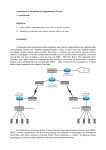
In many data communication applications
asymmetric cryptographic systems are in use. One
of the most known is the RSA algorithm. Although
it is very simple to describe, the RSA system is very
demanding with respect to computational resources.
The amount of traffic on the web sites requiring
authentication and key exchange causes heavy load
on the ISP’s computer resources. The purpose of
this demo-project done at the Danish Technological
Institute was to demonstrate that a high speed RSA
off-load engine is simple and fast to implement
using FPGA’s.
Some of the arguments for using FPGA’s are
outlined below, and they do cause a speed-up for
many applications, especially Digital Signal
Copyright © 2008 Danish Technological Institute
Processing applications
applications:
and
Cryptographic
•
FPGA’s
are
well
suited
for
implementing cryptographic algorithms.
There are several approaches taking
advantage of the blocks of the FPGA’s the most important are the DSP blocks
which are implemented in both Xilinx
and Altera FPGA’s, but also the RAM
blocks which have a size that matches
the intermediate results and the keys.
•
FPGA’s have the reputation that they
operate fast. If you compare the clock
frequencies of FPGA’s with processors,
the FPGA seem to be slow, but where
common off-the shelf processors can do
a few operations per clock cycle FPGA’s
can do several thousand operations per
clock cycle - e.g. the soon to come
Page 1 of 8
Altera Stratix-4 II EP4SE680 can do 1360
18x18 bit signed multiplications per clock
cycle.
•
FPGA’s are highly configurable - a SRAM
based FPGA can be reprogrammed an
unlimited number of times, making it
possible to change the operation during the
life time of the hardware used.
One of the disadvantages is that developing
applications for FPGA’s is a time consuming and
cumbersome task; the programmer must have a
thorough understanding of the programming
language (VHDL or Verilog) and also of the
underlying hardware. Therefore moving to a higher
level of abstraction and using a tool supporting this
higher level of abstraction significantly moves the
effort from detailed implementation to algorithm
refinement and verification.
The entry barriers such as the required knowledge
of the hardware are reduced, because the developers
do not need to implement one single line of VHDL.
The result of this is that FPGA development is
turned into model-based development instead of
pure VHDL implementation.
RSA Cryptosystem
Until 1997, the history of RSA was that Ron Rivest,
Adi Shamir and Leonard Adlemann first described
the RSA algorithm in 1977, and MIT was granted a
US patent in 1983. The patent expired in September
2000. However in 1997 Clifford Cocks work by the
UK intelligence agency GCHQ was made public.
Clifford Cocks work dates back to 1973 and
essentially describes the RSA Cryptosystem. The
algorithm did not come into use at that time [Singh
2000].
The following definition is based on [Stinson 2006].
Definition 1: RSA Cryptosystem
Let n = pq, where p and q are primes.
Copyright © 2008 Danish Technological Institute
Let P = C = Zn and define
K = {n, p, q, a, b} : ab ≡ 1 mod Φ (n)
where Φ(n) = (p − 1)(q − 1), because p and q are
both primes. For K = (n, p, q, a, b), define:
eK(x) = xb mod n and dK(y) = ya (mod n)
(x, y ∈ Zn).
The values n and b comprise the public key, and
the values p, q and a forms the private key.
Note that RSA is not a secure system, but the
level of security is defined by the use (or the
misuse) of RSA. The RSA is one of the most
famous cryptosystems and because RSA is a
very resource-demanding cryptosystem, RSA is
used as a sample application for calculations
modulo some large n, however there are other
cryptographic
applications
in
which
multiplications modulo some large n can be
used, e.g. Diffie-Hellman, El-Gamal, not to
mention elliptic curve algorithms [Stinson 2006].
The problem with these cryptosystems is that the
calculation of a product modulo n (and therefore
also exponentiation) is time-consuming. Either
division or a series of subtractions must be used,
but most algorithms for division can only
calculate one (or two) bit(s) per cycle, hence a
complete multiplication of a*b mod n, when n is
a 1024-bit modulo might at least take 32+1024
cycles, where the 32 cycles are used to calculate
the product and the 1024 cycles are for the trial
division. It is assumed that 2 bits can be
calculated per cycle.
So if there is a way to calculate a number
modulo n which is faster than the computation
time mentioned above, cryptography using RSA
becomes faster. This also becomes important as
the required key sizes increase due to the
development in both the computational power
and the skills of the cryptanalysts.
A scheme proposed by Peter Montgomery
[Montgomery P. 1985] has been accepted as one
Page 2 of 8
of the best algorithms to calculate integers modulo a
large number; the algorithm will be described in the
next section.
Montgomery Multiplication
One example is exponentiation using a square
and multiply approach as described in [Jensen
T.D. et.al., 2006] and [Menezes et. al., 1997] .
This approach forms the basis of the
implementation described in this paper.
The Montgomery Multiplication is based upon the
fact that for {x, y < m, m odd integer | ∃z < m} such
that:
z 2n (mod m) = x y (mod m)
(1)
Because m is odd, equation 1 can be written as:
2−nz 2n = 2−n xy (mod m)
Which can be rearrange such that
z = xy 2−n (mod m) = xy r−1 (mod m), r = 2n (2)
The latter part of formula (2) is the Montgomery
product. An algorithm calculating the Montgomery
product is outlined in algorithm 1, the proof for the
correctness of this algorithm can be found in
[Montgomery P. 1985] and [Jensen T.D, 2006] .
The correctness of the square and multiply can
be seen by a sample using 5 as the exponent:
step
initial
initial(second)
1
The Montgomery product does not seem to be
usable by itself, but if you instead of calculating
MontProd(a, b) calculate:MontProd(a·r, b·r) then the
result would be:
MontProd(a·r, b·r) = a·r ·b·r·r−1 mod n
= a·b·r mod n
This property of the Montgomery product can be
used when calculating several multiplications in
series as described in Montgomery’s Paper
[Montgomery P. 1985].
Copyright © 2008 Danish Technological Institute
2
3
final
Results (all modulo n)
x = x·r2·r−1 = x·r
A = 1·r 2· r−1 = r
A = (A·A·r−1) ·(˜x) ·r−1
= r· r·r−1· x· r· r−1
= x·r
A = (A·A) · r−1
= (x · r) · (x · r) · r−1
= x2r
A = (A·A·r−1)·(˜x) ·r−1
= x2r· x2r·r−1·x·r·r−1
= x5r
A = x5·r·r−1 = x5
Note that the second product calculated in the
initial step is only necessary each time a new
modulo is generated, for systems with a fixed
Page 3 of 8
modulo this step can be omitted, or if the system has
storage for the modulo e.g. in local RAM.
IMPLEMENTATION DETAILS
RELATED WORK
In the following the details of the
implementation flow are outlined, this flow is
based upon the MatLab development flow used
at the Danish Technological Institute (DTI).
Other implementations
Two major algorithms for reduction modulo n are
the Barrett algorithm and the Montgomery
algorithm. The reason for choosing Montgomery
instead of Barrett (or a classical trial division) is that
Montgomery reduction scales very well for
increasing operand sizes. This means that the
computational complexity increases much more
slowly for the Montgomery reduction than for both
the classical and the Barrett Reduction. Furthermore
exponentiation using the Montgomery product have
been verified to be superior to both classical and
Barrett [Bosselears 1993].
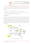
The Algorithm
Before we can use the Montgomery algorithm in
MatLab, we need to elaborate on the algorithm.
First a small dataflow graph (DFG) describing
the calculations using the Montgomery algorithm
are depicted in Figure 1:
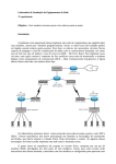
Other implementations using FPGA’s have been
proposed, for example [Fry and Langhammer 2005],
this implementation does not take advantage of the
built-in multipliers on most modern FPGA’s,
resulting in a low speed (12 operations per second
for a 1024 bit key), however this implementation is
more efficient (900 LE’s Altera Nomenclature ).
A software implementation for many cryptographic
algorithms can be found on www.cryptopp.com,
there are also benchmarks for two kinds of Pentium
processors, and one AMD processor. The best result
for 1024-bit RSA is 0.07 milliseconds for one
encryption (public exponent 17), which is 25.000
operations per second. It is important to note that
MMX/SSE2 specific assembly language routines
are used for integer arithmetic. The result is
achieved on an AMD Opteron processor that is
running at 2.4 GHz.
In addition to the above algorithms the classical
“grammar school” products of the computational
complexity O(ln2(n)) can be enhanced – using FFT
techniques the complexity can be reduced to O(n ln
n ln ln n) [Crandall and Pomerance 2005]
Copyright © 2008 Danish Technological Institute
Figure 1 the Montgomery algorithm.
Using the algorithm depicted in figure 1 the
following should be noted (With the prerequisite
that all operations are performed base 2, binary
representation, inputs use d bits):
•
The ’M’ operation is a modulooperation, and as long as r has the form r
= 2d, then performing an operation
modulo r means that only the lower d
digits will be used in the operation
following the modulo operation.
Page 4 of 8
•
•
With the above argument, the division by a
number r = 2d, means to shift down d bits.
The variables t and m2 can be represented
by 2 · d bits and y1 can be represented with
at most d + 1 bits.
It is important to be aware of the changes of
representation when implementing in Simulink, and
also the implementation of the stimuli generators in
MatLab.
MatLab sub-development cycle
The MatLab development cycle is considered
necessary to be able to compare the results with the
later Simulink sub-development cycle; In MatLab
the algorithm is simple to implement, and can
therefore be used to verify the correctness of the
following Simulink sub-development cycle.
Furthermore some additional functions are
necessary to be able to generate the test vectors; the
most important is a multibit Greatest Common
Divisor Algorithm (gcdwide) which can operate on
signed integer operands of any size. Also a function
to generate stimuli for the Simulink simulator was
developed in MatLab. Finally a utility for dumping
the results using 16-bit words, were implemented to
aid the debugging in the following development
cycles. The above algorithms demand the capability
to handle very large numbers, which MatLab does
not support natively, but the Fixed-Point Toolbox
does - and the Simulink Fixed-point tool box does
partly. For details about the MatLab Fixed Point
Toolbox please refer to [MathWorks FPT 2008]. It
is important to mention in this context that the
FixedPoint Toolbox has two objects numerictype
and fimath. The numerictype object handles the
type size and fimath determines the mathematical
operations.
The following numerictype object is used (for 1024
bit operands):
Note that the numbers used here are signed, the
reason for this is that the gcdwide algorithm
returns the result g = ax+by which implies that
one of the operands a and b must be negative if g
= 1.
In the above figure it can be seen that there are 2
more bits in the wordlength, the reason for
having 2 extra bits, one for the sign and one for
the leading digit in the ‘r’ operand of the
Montgomery algorithm.
The fimath object matches the numerictype
with respect to word sizes; additionally we use
the following modes:
RoundMode: fix
OverflowMode: wrap
Using these fixed point toolbox objects emulates
the
behaviour
of
the
usual
d-digit
implementation on most computers and
especially the behaviour of the ’SIGNED’ and
’UNSIGNED’ data types used in the standard
IEEE VHDL packages (numeric standard).
3.3 Simulink sub-development cycle
In this section the most important achievement
of the Simulink sub-development cycle is
presented. This is the Multiplication block
depicted in Figure 2.
DataTypeMode: Fixed-point:
Binary point scaling
Signed: true
WordLength: 1026
FractionLength: 0
Copyright © 2008 Danish Technological Institute
Page 5 of 8
1
restart
restart
restart
0:0
-CConstant 2
5
not _domult
OR
Logical
Operator
qual_ip
1
multiplicator
z
Unit Delay 4
1
z
Unit Delay 3
Switch
qual_ip
Figure 3: The principle of the multiplication,
step 1 (16*64 bit).
Matrix Multiply
3
multiplicator
multiplicator
4
s hiftin _wren
shiftin _wren
This is done 64 times, and for each of the 64
iterations the result is shifted downwards 16 bit,
as depicted in Figure 4.
shiftin _wren
wr_en
dataout
2
multiplicand
multiplicand
dataout
datain
dataout_m
shift
Terminator
ser2par
6
shift
Figure 2: The Engine of the Montgomery
Multiplication (product part).
During the Simulink sub-development cycle the
model of the exponentiation was developed and
further refined. The most important task was to
make sure that the following code generation step
did not generate any product, with operand widths
greater than 18 bits. This is due to the fact that this
would prevent the implementation to take advantage
of any hardened IP’s in the hardware such as Xilinx
DSP48’s or Altera’s DSP’s. The DSP48 can
perform fast multiplications of 18 bit operands, this
is not sufficient for cryptographic purposes such as
1024 bit multiplication. Therefore it is advantageous
to split the operations up into 16-bit operations
resulting in 32-bit results. In order to perform 1024bit multiplications 64 DSP48’s are cascaded into
one 16x1024 bit multiplication, resulting in 64 32bit numbers.
Each 32-bit number is split into two 16-bit numbers,
so that the most significant 16-bit word is added to
the least significant computer word of the preceding
computer word. The result is a 16+1024 bit word
containing the result of the first 16x1024 bit
multiplication; this is depicted in Figure 3.
Figure 4: The principle of the multiplication,
step 2 (16*64 bit).
This accumulation step is performed by the
Simulink model depicted in Figure 5.
1
0:0
-CConstant 4
1
Switch 2
z
Unit Delay 2
Extract 16 Bits
Lower End
Extract Bits5
Vector
0:0
Concatenate 4
U
Y
product
Selector
U
Y
Selector 1
Extract 2 Bits
Upper End
0:0
0
Constant 1
Extract Bits3
Figure 5: The Engine of the Montgomery
Multiplication (Accumulator part)
The result is a 1024-bit by 1024-bit
multiplication, calculating a 16-bit fraction of the
result per cycle starting with the least significant
word. A complete 2048 bit result can be
calculated within 128 cycles. If the result of the
Copyright © 2008 Danish Technological Institute
Page 6 of 8
multiplication is to be done modulo 1024, then the
result is ready within 64 cycles.
The most interesting block of the engine is the
matrix multiply block (Figure 1), which is
responsible for multiplying a 16 bit number with a
vector containing 64 16-bit numbers. Due to this
partitioning of a 1024 bit number into 16*64-bit, a
set (64) of small multiplications are generated in the
VHDL code instead of one single multiplication.
These small multiplications make the synthesis of
the code simple, and portable between any FPGA
technology, having 16 bit multipliers built-in.
larger key): therefore this figure has been
increased with a factor 200 to match the other
results. Note the low power consumption
compared with the speed of the core; not only
are our results superior compared with the results
from the software implementation when it comes
to power consumption, and even in a pure speed
comparison our core has the best performance.
The results in Table 1 were obtained targeting a
Xilinx Virtex 4SX-25 device speedgrade-12,
using ISE 10.1.
Type
Usage
TI-RSA
7505
LUTs
7505
LUTs
7000
Les
1 GPP
Simulink Code Generation
The Simulink code generation is straight forward
and is performed as described in the Simulink HDL
coder user manual [MathWorks shdl 2008], albeit
with some changes; First of all there is no (direct)
RAM support in Simulink, the user must either
write a new RAM or use the samples from
hdldemolib. In this case the latter approach was
taken. A few of the standard options were altered;
such as using “rising edge”, however they
have little effect on the code generation.
TI-RSA
(floorplan)
ARSA
Crypto++
Speed
Power
(Kops)
33000
1W
52000
~1W
12/
(2400)
25000
N.A.
90W
Table 1: Comparison of the TI-RSA
implementation with other implementations.
4.2 Verification
The result is a set of VHDL files, which matches the
expected results very well. In the second run a
testbench was generated, to validate the result. The
testbench verified for each clock cycle that the
Device Under Test (DUT) matched the expected
output, so an error could be detected at the exact
time when would occurs. The only obstacle using
this testbench is that result masking is not possible;
this is useful when using the testbench with
synthesised or placed and routed netlist.
RESULTS
Implementation
The implementation results are listed in table 1, the
numbers are calculated using 17 as encryption
exponent, and a 1024 bit number as modulo, except
for the ARSA-core which uses another (probably
Copyright © 2008 Danish Technological Institute
To verify the implementation a sample tuple
(message, key, cipher) was used; this tuple was
the same as used in [Jensen T.D et. al., 2006] .
The result from the simulation was compared
with the result from the MatLab calculations and
no difference was found. The same simulation
was also exported to VHDL using the testbench
generator; the generated testbench is a self
checking testbench resulting in either a
“PASSED” or “FAILED” output from the
console of the simulator - the result was
“PASSED”.
A comparison between the Simulink Model, the
ISE simulation and the (HIL) Hardware in the
Loop test is depicted in figure 7. The results are
identical which was also verified by comparing
the output (using the “ToWorkspace” block)
with the cipher text from the test-tuple.
Page 7 of 8
using a Virtex-4 SX-25C-12 increased the
maximum Clock Frequency from 150 MHz to
204 MHz, both breaking the original goal of
125MHz.
REFERENCES
Figure 6: Output from 3 simulations of the RSA
core
CONCLUSION
The major achievement of this project was the
ability to generate a RSA core using Simulink,
without writing a single line of VHDL.
This also lowers the implementation time and
requirements for the staff: VHDL programmers are
usually high-skilled developers, both costly and
rare. Lowering the requirements for VHDL
specialists makes FPGA development simpler and
less costly for small and medium sized companies,
and furthermore moves the effort needed from
implementation to application. One skill which can
not be ignored is the required knowledge of the
transformation from a model into VHDL code
which effectively uses the hardened IP blocks either
by instantiation or inference is important, but when
comparing this the required knowledge of the
semantics of VHDL when doing it by hand our
preference is clear: It is definitely more interesting
to develop applications using a higher level
approach than implementing low-level (or lowerlevel) VHDL. One of the main objectives when
doing model based development is the lack of
manual transformations from one level of
abstraction to another, therefore it is interesting to
note that from the beginning of this demonstration
case, the goal was to aid the implementation using
Simulink, but the final result was that all code
generated was done by Simulink.
Still robust craftsmanship is requested when you
want to break the limits: Using tools as PlanAhead
and manual pipelining the maximum performance
Copyright © 2008 Danish Technological Institute
[Bosselaers 1993] Anton Bosselaers, Rebe
Govaerts, and Joos Vandewalle. (1993)
Comparison of three modular reduction
functions. Advances in Cryptology CRYPTO
’93.
[Crandall and Pomerance 2005] Crandall, R.,
Pomerance C., Springer 2005. Prime Numbers,
Second Edition.
[Fry and Langhammer 2005] John Fry and
Martin Langhammer. (2005) RSA & public key
cryptography in FPGA’s.
[Jensen T.D et. al., 2006] Torben Ditlev Jensen,
Niels Ladegaard Beck, Christer Vindberg, Belma
Boyraz, and Carsten Siggaard. (2000) RSA
cipher optimizations in software and hardware.
The MathWorks, Inc [MathWorks FPT 2008].
(2008) Fixed-Point Toolbox(TM) 2 - User’s
Guide, version 2.2.
[MathWorks shdl 2008] The MathWorks, Inc
(2008) .Simulink HDL Coder(TM) 1 - User’s
Guide, version 1.3
[Menezes et. al., 1997] Alfred J. Menezes, Paul
C. van Oorschot, and Scott A. Vanstone. (1997)
Handbook of Applied Cryptography. Discrete
Mathematics and Its Applications. CRC Press.
[Montgomery P. 1985] Peter L. Montgomery.
(1985) Modular multiplications without trial
division. Mathematics of Computation Vol. 44,
Not 170, pages 519–521, Apr 1985.
[Singh 2000] Simon Singh (2000). The Code
Book, Fourth Estate Limited.
[Stinson 2006] Douglas R. Stinson D. R.,
Chapman & Hall/CRC (2006), Cryptography,
Theory and Practice.
Page 8 of 8