1
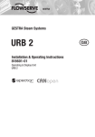
Professional Headend Solutions
USER MANUAL
USER MANUAL
MPEG-ENCODER VEA 107
MPEG-ENCODER VEA 10x ( 917x.xx ) User manual
Rev. 10 (2008)
BLANKOM Antennentechnik GmbH/ Subject to modifications
Content list
1. Basic installing and operating instructions____________________________________________ 2
1.1 Safety instructions
________________________________________________________ 2
1.2 Contact
________________________________________________________ 2
1.3 General description of functions ____________________________________________________ 3
1.4 “EASY Multiplexing”
________________________________________________________ 3
2. Explanation of the functional elements _______________________________________________ 4
2.1 Front view
________________________________________________________ 4
2.2 Rear view
________________________________________________________ 4
2.3 Audio input socket allocation (8 poles, DIN 45326) _____________________________________ 5
3. Operating instructions
________________________________________________________ 6
3.1 Assembly and commissioning _____________________________________________________ 6
3.2 Operation using factory settings (no further configuration) ________________________________ 6
3.3 Configuration via the Ethernet interface ______________________________________________ 7
3.3.1 Connecting the network to the computer __________________________________________ 7
3.3.2 Service and setup
________________________________________________________ 8
3.3.3 Default configuration ________________________________________________________ 9
3.3.4 Detailed configuration _______________________________________________________ 10
3.3.4.1 The single device system (one Master)_______________________________________ 10
3.3.4.2 Multi-device systems (cascades)____________________________________________ 12
3.3.4.2.1 The double device system (one Master, one Slave) __________________________ 13
3.3.4.2.2 The triple device system (one Master, two Slaves)___________________________ 15
3.3.4.2.3 4- or 5-device systems (one Master, up to four Slaves) _______________________ 17
3.4 Extended configuration, individual settings___________________________________________ 18
3.4.1. Exclusive coding of audio signals ______________________________________________ 18
3.4.2 TTX processing, VPS-WSS ___________________________________________________ 19
3.4.3 Transport Stream bitrate (TS out bitrate), system bitrate _____________________________ 19
3.4.4 Firmware updates
_______________________________________________________ 21
3.4.5 Factory settings
_______________________________________________________ 22
3.4.5.1 Setting by using the accompanying operator software ___________________________ 22
3.4.5.2 Setting by using the “Factory Set” key________________________________________ 22
3.4.5.3 Setting by using the maintenance software____________________________________ 22
3.4.6 Integration into the headend management system for B-LINE or C-LINE ________________ 23
3.5 Options, updates/upgrades ______________________________________________________ 24
3.5.1 RDS data transfer
_______________________________________________________ 24
3.5.2 SDI signal interface _______________________________________________________ 24
3.5.3 Signal encoding
_______________________________________________________ 25
3.5.4 Data transmission (customised)________________________________________________ 25
4. Appendix
_______________________________________________________ 26
4.1 Technical data
_______________________________________________________ 26
4.2 Versions, options
_______________________________________________________ 27
4.3 Block diagrams
_______________________________________________________ 28
4.3.1 Basic VEA 107/108 version (analogue A/V + VBI processor) _________________________ 28
4.3.2 Optional versions, VEA 107 and VEA 108 ________________________________________ 29
4.4 Accessories
_______________________________________________________ 31
4.4.1 Accessories as standard _____________________________________________________ 31
4.4.2 Optional accessories _______________________________________________________ 31
4.4.2.1 Cables
______________________________________________________ 31
4.4.2.2 Plug-in connectors_______________________________________________________ 32
4.5 Glossary and abbreviations ______________________________________________________ 32
MPEG-ENCODER VEA 10x (917x.xx ) Manual
Updated 10 (2008)
BLANKOM Antennentechnik GmbH, Germany /Subject to modifications
1. Basic installing and operating instructions
1.1 Safety instructions
- When assembling and commissioning the VEA MPEG2 Encoders and executing the settings, always
follow the accompanying instructions exactly.
- The devices are not to be assembled and brought into use by anybody who is not an authorised
technician.
- When components are being installed into headends, ensure that EMC regulations are observed.
- All assembly, installation and cable connection must take place with cold state of the device.
- The provisions of DIN EN 50083 must be observed at all times when working
with the equipment. In particular, DIN EN 50083/1 regarding safety may on no account be ignored.
- The devices come under protection classification I. It is absolutely necessary, therefore,
to insert the mains plug into a socket with protective contact.
Note:
Connecting external video sources of which the mass has a different potential from that of the VEA107
or VEA108 may cause “hum” (avoided by matching the potentials or isolating them from each other).
1.2 Contact
If there are any questions or problems, help is available from
BLANKOM Antennentechnik GmbH
Hermann-Petersilge-Str. 1
07422 Bad Blankenburg
Germany
Telephone: +49 (0) 3 67 41 / 60-0
Fax:
+49 (0) 3 67 41 / 60-100
Email:
Web:
[email protected]
www.blankom.de
2
MPEG-ENCODER VEA 10x (917x.xx ) Manual
Updated 10 (2008)
BLANKOM Antennentechnik GmbH, Germany/Subject to modifications
1.3 General description of functions
The MPEG2 Encoders VEA 107/108 are components of the A-LINE headend system.
Depending on the device and version (see Section 4.2), they serve to encode up to 3 analogue or
uncompressed digital audio and/or visual signals, integrating them into the DVB Transport Stream.
Analogue video and audio signals are fed into the system via the respective analogue input ports (video
and audio); for “audio-embedded” digital A/V signals, the devices can be equipped with serial digital
interfaces (SDIs).
The output signal is a DVB Transport Stream as per ISO13818-1 and is transmitted from an ASI interface.
ASI stands for Asynchronous Serial Interface. This signal can be fed into the cable TV network with the
aid of a QAM modulator.
The devices, being MPEG2 encoders with a five-fold “cascade” facility, are effectively Transport Stream
Multiplexers, producing “bouquets” of up to 15 programmes. These, again, are broadcast via the ASI and
can be further processed in the same way as described above.
There are suitable QAM modulators available, for instance in BLANKOM’s A-LINE headend system. To
choose the required type and to find out how to deal with these additional components, please refer to the
product catalogue and the relevant description.
Notes:
The ASI input ports may only be used for Transport Streams from the VEA 107 or VEA 108 encoders. It is
not possible to incorporate ASI signals from other systems into the Transport Stream.
The output signal contains all the tables necessary to the programme and associated services (PAT, PMT
and SDT). An NIT will be generated but will not contain any network-specific information. A succeeding
QAM modulator is responsible for the necessary adaptation of the NIT.
There are options permitting RDS data transfer via additional channel-specific access ports and enabling
additional customer-specific details to be included via the Ethernet interface (see Section 3.5).
1.4 “EASY Multiplexing”
“EASY Multiplexing” is a simple, uncomplicated means of producing a digital ASI Transport Stream.
Depending on which device is in use, up to 3 analogue (A/V) signals or up to 3 digital (SDI) signals can
be combined simply by one VEA 107 or VEA 108 into a single standard DVB signal, by means of “Plug
and Play”. The parameters necessary have been set in the device at the factory
(see Section 3.2).
See Section 3.3.4.2 for details of how VEA 107 or VEA 108 cascade systems using multiple devices are
brought into use and how the Transport Stream can be manipulated from the HTML user interface.
3
MPEG-ENCODER VEA 10x ( 917x.xx ) Manual
Updated 10 (2008)
BLANKOM Antennentechnik GmbH, Germany/Subject to modifications
2. Explanation of the functional elements
2.1 Front view
Fig. 1: Front view, VEA 107 or VEA 108
LED display
POWER
INPUT VIDEO A, B, C
LED not illuminated:
INPUT TS (Master Mode)
INPUT TS (Slave Mode)
Operating voltage displayed
LED illuminated: video signal recognised
no video signal or video signal does not match
standard
LED not illuminated
LED illuminated: ASI-TS signal at input port
LED flashing: no ASI-TS signal at input port
2.2 Rear view
Fig. 2: Rear view of VEA 107 or VEA 108 (with RDS option)
Input and output ports
VIDEO IN (A, B, C)
AUDIO IN (A, B, C)
ASI IN
ASI OUT
NET
RS232
RDS IN (A, B, C)
Video input ports
Audio input ports
Input port for Transport Stream
(activated only if device working as Slave)
Transport Stream output port
Ethernet interface (network connection point for
updating firmware, device control)
RS232 interface (firmware update, factory settings)
Input ports for RDS signals of channels A, B and C
(optional)
Sunk key
FACTORY SET
Resets all settings to factory settings
4
MPEG-ENCODER VEA 10x (917x.xx ) Manual
Updated 10 (2008)
BLANKOM Antennentechnik GmbH, Germany/Subject to modifications
2.3 Audio input socket allocation (8 poles, DIN 45326)
1 Stereo left+ or dual A+ or mono+
2 Shielding (mass)
3 Stereo right+ or dual B+
4 Stereo left- or dual A- or mono5 Stereo right- or dual B6 not used
7 not used
8 not used
Fig. 3: Pole allocation, audio socket
5
MPEG-ENCODER VEA 10x ( 917x.xx ) Manual
Updated 10 (2008)
BLANKOM Antennentechnik GmbH, Germany/Subject to modifications
3. Operating instructions
3.1 Assembly and commissioning
NB All assembly and connection must take place when no electricity has been connected.
On no account may the safety notes (see Section 1.1) be ignored.
The device is intended to be installed on sliding rails in a 19-inch rack.
It is secured from the front with the assembly set supplied.
One height unit must be allowed between devices for the avoidance of overheating. This may be
disguised with a louvered ventilation plate if desired.
Contact must be made for the video, audio and ASI signals at the A, B and C connection points on the
rear of the device using appropriate cables. Those listed in Section 4.4.2 are recommended.
From the ASI output port, the signal is sent either straight to the QAM modulator or to the succeeding
Slave.
As soon as all the wiring has been done for the signal, the mains cable can be connected and the device
switched on.
The operating status is shown by the LEDs on the front panel (see Section 2.1).
3.2 Operation using factory settings (no further configuration)
The VEA 107 or VEA 108 is delivered with optimal configuration as Master for 3 AV channels. It will be
functional with these settings without any further configuration. It is possible to get back the factory
settings at any time by using the sunk “Factory Setting” key (see Section 3.4.5).
All information on programmes and Transport Stream is neutral but can be adapted as necessary to
match the requirements of a cable network operator. To do this, it is necessary to call up the HTML user
interface via the Ethernet interface (see Section 3.3).
6
MPEG-ENCODER VEA 10x (917x.xx ) Manual
Updated 10 (2008)
BLANKOM Antennentechnik GmbH, Germany/Subject to modifications
The factory settings for the VEA 107 are summarised in the table which follows.
Parameters
Value
Notes
TS- ID (PAT, SDT, NIT)
Master / Slave
Provider name
Programme name
*****
Master
Provider
Prog - A
Prog - B
Prog - C
Dummy
deu
36
3 (+ Data)
5-digit serial number
Create NIT: (Master only)
Programme language
Mbps TS out bitrate
Used input channels
(number of AV channels)
Video system
PAL
System bitrate
Audio bitrate
Audio mode
TTX processing
8 Mbps
192 kbps
Stereo
Video IN
VPS-WSS
VPS
Total bitrate for TS (ASI-OUT)
To permit additional data (teletext etc.) to be
transmitted, a data channel is always allocated in the
Master. All programmes and the data channel have
an equal share in the overall bitrate. The maximum
system bitrate per channel is thus 36 / (n+1)
A choice can be made between PAL and NTSC for
each channel.
3 x A/V channels and 1 x data channel
The teletext information, contained in the video
signals for lines 7 to 15 and 19 to 22, also 320 to 328
and 332 to 335, will be digitized and then included in
the DVB Transport Stream.
VPS transmission and WSS active
Table 1: factory settings
3.3 Configuration via the Ethernet interface
If it is necessary to change the default configuration or to create a cascade of more than one VEA 107 or
VEA 108 to create a shared data stream (see Section 3.3.4.2), the HTML user interface must be called up
on a computer connected to the device(s).
How the user interface works is almost self-explanatory. Any special features of use will be explained in
the following chapters.
3.3.1 Connecting the network to the computer
System requirements:
- PC or laptop with 10/100 Mbit Ethernet interface
- Internet browser (such as Windows Internet Explorer)
Making the connections:
The VEA 107 or VEA 108 must be connected to the PC network using an Ethernet cable.
If connected directly to a PC, the Ethernet cable must be a cross-linked cable. The IP address of the VEA
107 or VEA 108 on delivery is 192.168.2.86.
The address of the network connection in the PC must be adapted to accommodate the IP address of the
VEA 107/108 (subnet mask: 255.255.255.0 / IP address: 192.168.1.XXX).
7
MPEG-ENCODER VEA 10x ( 917x.xx ) Manual
Updated 10 (2008)
BLANKOM Antennentechnik GmbH, Germany/Subject to modifications
Do not let XXX be exactly the same as the IP address of the VEA 107 or VEA 108.
When systems which are made up of more than one device as a cascade system are initially configured,
it is necessary to ensure that VEA 107 or VEA 108 transcoders are connected to the network one after
the other and configured separately, as the IP addresses of such transcoders on delivery are all the
same.
The IP address of the VEA 107 or VEA 108 is entered on the browser screen. When the link up has been
successfully made, the device produces a pop-up log-in window:
Fig. 4: Log-in window
Access to the configuration menu is password protected.
When the device is supplied, the password is “neu” (the German word for “new”).
It is also necessary to enter the 5-figure serial number of the device being connected to the computer.
This number is on the rear of the device. There are more labels showing the serial number contained in
the scope of delivery; if desired, they can be placed somewhere else for easier identification, for instance
on the front of the device.
Note:
If password or IP address are unknown or have been forgotten, the factory settings can be re-established
by pushing in the (recessed) “Factory Set” key (see also Section 3.4.5, Factory settings).
Afterwards the device is back in its state as delivered, with the access data and factory settings described
above.
The configuration menu appears once log-in has been accomplished.
It is divided into three:
- Service and setup
- Default configuration
- Detailed configuration
The following sections describe the functions under each heading.
3.3.2 Service and setup
This area is configured by clicking soft-keys as appropriate to select the desired function (see Figure 5).
The following actions are possible:
- Password change
- Factory setting
- Hilfe / Help
- Download MIB
- Set Date & Time
Changing the password for the device
Resets all settings to factory settings
Calls up the help pages in German or English
Downloads the MIB file specific to the device (ME.mib)
to serve the system via SNMP
Sets the clock within the device
8
MPEG-ENCODER VEA 10x (917x.xx ) Manual
Updated 10 (2008)
BLANKOM Antennentechnik GmbH, Germany/Subject to modifications
Fig. 5: Setup and service menu
3.3.3 Default configuration
The preselection window shown in Figure 6 makes it simple to adopt automatic pre-settings of the best
possible parameters for starting up a single, double or triple device system.
1 Device
Single device system with 3 programmes
2 Devices
Double device system with 6 programmes
3 Devices
Triple device system with 9 programmes
Fig. 6: Menu for default configuration (factory settings)
This is where the mode of operation in the cascade of each individual VEA 107 or VEA 108 is entered (as
Master, Slave, Slave1 or Slave2). (In special cases, it is possible to cascade a maximum of 5 devices,
see Section 3.3.4.2.3.) The total Transport Stream is thereby shared across the individual programmes
and the data channel.
At the same time, automatic programme names of a neutral nature are allocated, as are audio/video PIDs
and service IDs in ascending order (see Tables 2 and 3).
Configuration Input
Master
A
B
C
Prog - A
Prog - B
Prog - C
0x11 + offset
0x12 + offset
0x13 + offset
0x111
0x112
0x113
0x211
0x212
0x213
0x311
0x312
0x313
0x411
0x412
0x413
RDS
(piped
mode)
0x319
0x31A
0x31B
Slave1
D
E
F
Prog-D
Prog-E
Prog-F
0x21 + offset
0x22+ offset
0x23 + offset
0x121
0x122
0x123
0x221
0x222
0x223
0x321
0x322
0x323
0x421
0x422
0x423
0x321
0x32A
0x32B
Slave2
G
H
I
Prog-G
Prog-H
Prog-I
0x31 + offset
0x32 + offset
0x33 + offset
0x131
0x132
0x133
0x231
0x232
0x233
0x331
0x332
0x333
0x431
0x432
0x433
0x331
0x33A
0x33B
Slave3
J
K
L
Prog-J
Prog-K
Prog-L
0x41 + offset
0x42 + offset
0x43+ offset
0x141
0x142
0x143
0x241
0x242
0x243
0x341
0x342
0x343
0x441
0x442
0x443
0x341
0x34A
0x34B
M
Prog-M
0x51 + offset 0x151
N
Prog-N
0x52+ offset 0x152
O
Prog-O
0x53 + offset 0x153
Table 2: Automatically allocated service IDs and PIDs
0x251
0x252
0x253
0x351
0x352
0x353
0x451
0x452
0x453
0x351
0x35A
0x35B
Slave4
Programme Service
Name
PMT
Video
Audio
TTX
9
MPEG-ENCODER VEA 10x ( 917x.xx ) Manual
Updated 10 (2008)
BLANKOM Antennentechnik GmbH, Germany/Subject to modifications
To get unique service IDs if there are several cascades in one headend, an offset is automatically added
for the parameter “cascade number within network” (CNr):
1
2
3
4
Cascade no.
0
0x04
0x08
0x0C
Offset
Table 3: Offset addition for the respective cascade numbers
5
0x80
6
0x84
7
0x88
8
0x8C
3.3.4 Detailed configuration
The detailed configuration enables DVB identification characters and parameters such as provider name,
network ID, program name, transmission parameters etc to be individually set.
The user interface enabling detailed configuration is basically the same in all BLANKOM devices
whatever the system.
Note:
Whenever individual settings are made, care should be taken to ensure that the figures entered into the
configuration mask make sense technically and/or count as valid figures.
3.3.4.1 The single device system (one Master)
This is the configuration which is basically the factory settings on delivery.
It can also be selected in the “1 Device” window of the menu of the default configuration (see Fig. 6).
Possible detailed configuration options are:
IP address, IP subnet mask
TS-ID
Provider name
Network ID
Programme names
(necessary if the device is being integrated into an existing network)
(the 5-figure serial number is entered as default)
(the default entry is “Provider”)
(the default entry is “100”)
(entered at first as “Prog-A”, “Prog-B” and “Prog-C”)
Figures 7-1 and 7-2 show all the possible setting options.
The default is 3 channels with standard figures for the system bitrate.
If these preset bitrates are being changed, account should be taken of the TS out bitrate which has been
set and the number of channels to be transmitted, plus data channel and whether the new bitrates are
compatible with these conditions (see Section 3.4.3).
10
MPEG-ENCODER VEA 10x (917x.xx ) Manual
Updated 10 (2008)
BLANKOM Antennentechnik GmbH, Germany/Subject to modifications
Example: “Master” in a “1 Device” configuration
IP-Address
The network address is set to 192.168.2.86 in state as delivered and
when “Factory setting” is pressed. The IP address can be altered in
this menu. If there is no DHCP service available, the pre-set
address is used.
TS-ID (Transport Stream ID)
The Transport Stream identification is allocated individually. It may
appear only once in the cable network. The 5-figure serial number is
entered as default.
Create NIT
The Master device can create the framework for an NIT (Network
Information Table) if required. The options are:
off - no NIT will be created, dummy – an empty NIT frame
will be created, Satellite / Cable / Terrestrial – an NIT frame
with the details appropriate to the TV format will be created.
Network ID
This must be exactly the same for all DVB channels within a cable
network.
Cascade Number within Network
Each cascade of devices (max. 8) is given a separate
address between 1 and 8 so that the PID is
individualised (see Section 3.3.3)
Fig. 7-1: Menu, detailed configuration
Data PID enabled
This is a device option allowing customised data to be inserted into
the TS (see Section 3.5.4).
11
MPEG-ENCODER VEA 10x ( 917x.xx ) Manual
Updated 10 (2008)
BLANKOM Antennentechnik GmbH, Germany/Subject to modifications
Video System / (Radio)
This is for selecting the video standard (PAL, NTSC...) for the
incoming signal. If the setting is “OFF”, only radio signals will be
encoded (MPEG radio).
System Bitrate
The System bitrate is the bitrate (bandwidth) of a channel. It
depends on the TS out bitrate and the number of channels within
Transport Stream (see Section 3.4.3).
Audio Mode
For setting the sound mode: stereo, joint stereo, mono, dual
channel, Use VPS.
If use VPS is set, the relevant broadcaster details in the VPS line
will be adopted into the DVB signal.
TTX processing and VPS-WSS
Options (see Section 3.4.2).
Fig. 7-2: Menu, detailed configuration
3.3.4.2 Multi-device systems (cascades)
Because the VEA 107 or VEA 108 is a device which can be cascaded, multi-device systems can be
created.
If this is done, changes need to be made to the set parameters from the HTML pages. Also, signal
connections must be made (ASI-OUT/IN) between the devices using 75-ohm BNC cables (see Figure 8).
12
MPEG-ENCODER VEA 10x (917x.xx ) Manual
Updated 10 (2008)
BLANKOM Antennentechnik GmbH, Germany/Subject to modifications
Fig. 8: Circuit diagram of a 3-device cascade
3.3.4.2.1 The double device system (one Master, one Slave)
From the double device system upwards, each device must be individually configured. Ethernet
connections are established separately, starting with the Master (see Section 3.3.1).
For each device in the cascade, Master and Slave are designated under “2 Devices” in the menu of the
default configuration by making the appropriate selection. Optimal bitrates for 6 programmes, also neutral
programme names, are automatically assigned (see Section 3.3.3 and Fig. 6).
If a device is being configured as a Slave, the ASI data stream input port is activated in addition.
Once the default configuration has taken place for the 2-device system, there will be a system bitrate
available to each channel of 4.92 Mbps. The detailed configuration is as in the single device system, with
a few special features to note.
All devices in a cascade must be given the same TS ID so that they can create a shared Transport
Stream.
The TS ID can be any number between 1 and 65535. However, at the start the TS ID will be the 5-digit
serial number of the VEA 107 being initialised. In the simplest case, the TS ID of the Master should also
be entered for the Slaves.
In cable networks with more than one DVB channel, each TS ID is allowed to appear only once, which
means that the TS IDs of the Transport Stream(s) generated by the (single or cascaded) VEA 107/108
device(s) must all be different and must be different from those of the Transport Streams from other
broadcasters. To avoid duplication it is therefore necessary for the TS IDs which are already allocated in
the cable network to be known before further Transport Streams are added.
13
MPEG-ENCODER VEA 10x ( 917x.xx ) Manual
Updated 10 (2008)
BLANKOM Antennentechnik GmbH, Germany/Subject to modifications
Example:
“Master” in a “2 Device” configuration
TS-ID (Transport Stream ID)
In 2- to 5-device systems the TS ID for all the devices (Master,
Slave 1 and so on to Slave 4) must be exactly the same. But it
may appear only once in the cable network.
Create NIT (Master only)
The decision as to generating NIT data must be made for
the Master and will affect the whole cascade.
Network ID
The network ID must be exactly the same for all DVB channels
within a cable network.
Fig. 9: Detailed configuration of Master (“Channel MUX” menu)
14
MPEG-ENCODER VEA 10x (917x.xx ) Manual
Updated 10 (2008)
BLANKOM Antennentechnik GmbH, Germany/Subject to modifications
Example:
“Slave” in a “2 Device” configuration
6 AV programmes are integrated when the default
configuration “Slave” is set here. The 3 programmes
produced by the Slave will be given the programme names
“Prog-D” to “Prog-F”. Individual programme names can be
entered here.
Fig. 10: Detailed configuration of Slave
3.3.4.2.2 The triple device system (one Master, two Slaves)
In the case of a triple device system, all three devices must be individually configured. The procedure is
as for the configuration of the double device system (see Section 3.3.4.2.1). First, the Ethernet
connections are, again, established separately, starting with the Master (see Section 3.3.1).
For each device in the cascade, Master and Slave are designated under “3 Devices” in the menu of the
default configuration by making the appropriate selection. Optimal bitrates for 9 programmes, also neutral
programme names, are automatically assigned (see Section 3.3.3 and Fig. 6).
If a device is being configured as a Slave, the ASI data stream input port is activated in addition.
Once the basic configuration has taken place for the 3-device system, there will be a system bitrate
available to each channel of 3.52 Mbps.
All devices in a cascade must be given the same TS ID so that they can create a shared Transport
Stream.
The TS ID can be any number between 1 and 65535. However, at the start the TS ID will be the 5-digit
serial number of the VEA 107/108 being initialised. In the simplest case, the TS ID of the Master should
also be entered for the Slaves.
15
MPEG-ENCODER VEA 10x ( 917x.xx ) Manual
Updated 10 (2008)
BLANKOM Antennentechnik GmbH, Germany/Subject to modifications
Note:
In cable networks with more than one DVB channel, each TS ID is allowed to appear only once, which
means that the TS IDs of the Transport Stream(s) generated by the (single or cascaded) VEA 107/108
device(s) must all be different and must be different from those of the Transport Streams from other
broadcasters. To avoid duplication it is therefore necessary for the TS IDs which are already allocated in
the cable network to be known before further Transport Streams are added.
Example: “Slave 2” in a “3 Device” configuration
9 AV programmes are integrated when the default configuration
“Slave 2” is set here. The 3 programmes produced by the Slave 2
will be given the programme names “Prog-G” to “Prog-I”.
Individual programme names can be entered here.
Fig. 11: Detailed configuration of Slave 2
16
MPEG-ENCODER VEA 10x (917x.xx ) Manual
Updated 10 (2008)
BLANKOM Antennentechnik GmbH, Germany/Subject to modifications
3.3.4.2.3 4- or 5-device systems (one Master, up to four Slaves)
For special situations, it is possible to combine up to 5 devices into a cascaded system. In principle, this
type of configuration will enable a Transport Stream to be created carrying a maximum of 15 AV channels
and a data channel. However, as the channels are equidistant from one another, there will only be 2.25
Mbps of bandwidth available per channel if the Transport Stream rate is 36 Mbps. If the maximum
Transport Stream rate can be used (43.2 Mbps) a bandwidth of 2.7 Mbps could be achieved per channel.
It must be said that the remaining bandwidth is only of limited suitability for the transmission of video
signals, so that these types of configuration are not really recommended for that purpose.
However, one special situation would be the digitalisation of radio programmes. The relevant
configuration is available without limit. For this task, too, as for the multi-device systems described above,
all the devices involved must be optimised individually. Again, Ethernet connections are established
separately, starting with the Master (see Section 3.3.1).
Below is an example of the settings for the individual devices.
Example:
Converting and combining 15 radio programmes
into one DVB Transport Stream
TS-ID (Transport Stream ID)
The Transport Stream identification is allocated individually. It
may appear only once in the cable network. All devices in a
cascaded system must use the same TS ID.
Master / Slave
To be selected according to the position of the device.
(Mbps) TS out bitrate
16.6 Mbps – 43.2 Mbps
1)
Used Input Channels (1…9[15])
Maximum number of channels: 15 (in a 5-device system)
Fig. 12: Channel MUX menu (15 radio programmes)
Create NIT (Master only)
The decision as to generating NIT data can only be made for
the Master.
Network ID
The network ID must be exactly the same for all DVB
channels within a cable network.
1)
This setting can be any between 16.6 Mbps and 43.2 Mbps. For 15 programme channels and one data
channel it is necessary to have 16x1024 kbps = 16.38 Mbps (cf. Section 3.4.3). Bandwidth not required is
filled with dummy traffic.
Further channel-specific settings must be made in the “1st, 2nd und 3rd Encoder” menus for the individual
devices.
17
MPEG-ENCODER VEA 10x ( 917x.xx ) Manual
Updated 10 (2008)
BLANKOM Antennentechnik GmbH, Germany/Subject to modifications
Programme Name
Individual programme names can be entered. The presettings are Prog-A …Prog-O.
Video System / (Radio)
“Off”: Only audio data will be encoded.
System Bitrate [1024…15000 Kbps]
“1024” : this minimum data rate is adequate to audio
transmission
Fig. 13: Encoder menu (15 radio programme)
Audio Bitrate
„384“: For highest quality audio transmission, select the
maximum value as there is plenty of bandwidth available for
radio.
3.4 Extended configuration, individual settings
The configurations described above allow easy generation of DVB-compatible Transport Streams. In
addition it is possible to set other special features (for example, data transfer).
3.4.1. Exclusive coding of audio signals
One special situation is the exclusive MPEG coding of audio signals.
For this task, too, as for the multi-device systems described above, all the devices involved must be
optimised individually.
The Ethernet connections are established separately, starting with the Master (see Section 3.3.1). The
“Video System / (Radio)” parameter in the encoder menu is set to “off”. The system bitrate of the encoder
channels can be set to the slowest value (1024 kbps). The TS out bitrate selected must be appropriate to
the number of programme channels. For example, for 15 programme channels and one data channel,
16x1024 kbps = 16.38 Mbps will be required (cf. Section 3.4.3). For the exclusive audio coding, the option
“RDS data transfer” (see Section 3.5.1) would be appropriate.
Note:
From software version 2.38 upwards, a system parameter “Audio Frames per PES Block (1…8)” has
been added as an extra menu item.
Fig. 14: “Audio Frames per PES Block (1...8)” system parameter
Although the standard allows 1 to 8 frames, this range is not supported from every connectable audio
device with an ASI TS input port known to BLANKOM. which, with an inappropriate combination of frame
value and audio bitrate, can lead to sound problems (for example, periodic breaks). With the additional
menu item, it is now possible to adapt the BLANKOM device to accommodate the one connected. All
“audio only” devices tested so far will work reliably with the setting “1” or “2”; devices for digital video and
audio signals (ASI TS) require the setting “4”.
18
MPEG-ENCODER VEA 10x (917x.xx ) Manual
Updated 10 (2008)
BLANKOM Antennentechnik GmbH, Germany/Subject to modifications
3.4.2 TTX processing, VPS-WSS
These two menu items control how teletext information and the VPS and WSS control signals which are
contained in the analogue signal will be captured, processed and adopted in the Transport Stream.
The following settings and functions are possible (Table 4):
Menu item
State
Function
TTX processing
VPS-WSS
OFF
Any
No teletext or VPS and WSS data adopted
TTX processing
VPS-WSS
Video IN
OFF
The teletext data contained in lines 7 to 22 and 320 to 335 are
digitalised and transmitted in the DVB Transport Stream
Teletext information from lines 7 to 15 and 19 to 22, also 320 to 328
and 332 to 335, will be digitized and then transmitted as part of the
DVB Transport Stream.
In addition, VPS and/or WSS (according to what has been selected)
will be digitized and then transmitted as part of the DVB Transport
Stream.
Table 4: Configuration options for TTX and VPS-WSS
TTX processing
VPS-WSS
Video IN
VPS
WSS
VPS+WSS
Note:
If the RDS option has been adopted for the device, the TTX processing and VPS-WSS functions are not
available.
3.4.3 Transport Stream bitrate (TS out bitrate), system bitrate
When deciding the Transport Stream bitrate, various aspects must be considered. For high quality video
transmission, the TS out bitrate should be as high as possible, while for transmission of small quantities
of data much slower bitrates are quite adequate (for example, 16.38 Mbps are sufficient for digital radio
with a maximum of 15 programmes, see also Section 3.3.4.2.3). Based on the TS out bitrate necessary in
the relevant case, the next higher bitrate in the menu must be selected.
In the “Channel Mux” menu the following bitrates are available (see Tab. 5):
TS out
bitrate
43.2
36.0
30.8
27.0
24.0
21.6
19.6
18.0
16.6
15.4
14.4
13.5
(Mbps)
Table 5: TS out bitrates which can be set
Notes:
The same bitrate must be set for all devices within a cascade.
The maximum possible bitrate which can be set is 43.2 Mbps. If this bitrate is used, however, there must
be a check made as to whether succeeding components such as modulators and up-converters can cope
with Transport Streams at the bitrate.
The Transport Stream bitrate (TSBR) is subdivided into slots (channels) of the same size.
It should be observed that the first VEA 107 (Master) always provides a slot for teletext, data and tables
as well as AV slots, so that the number of slots is always the number of AV channels (N) plus 1.
19
MPEG-ENCODER VEA 10x ( 917x.xx ) Manual
Updated 10 (2008)
BLANKOM Antennentechnik GmbH, Germany/Subject to modifications
The more channels are being broadcast, the slower is the system bitrate (bandwidth) available for each
channel (slot).
The maximum system bitrate (SBRmax) available in theory per encoder channel is therefore
SBRmax = TSBR / (N + 1)
In practice, approx. 10% of this value must be deducted as a safety buffer. The definitive formula is,
therefore:
SBRmax = 0.9 x TSBR / (N + 1)
The following examples will clarify this:
Example 1:
1-device system, standard TS out bitrate = 36 Mbps, 2 AV channels with maximum system bitrate
Parameters
TS out bitrate
Number of slots required
Value
36 Mbps
3
Maximum adjustable
system bitrate for
channels A and B
10,800 kbps *)
Notes
Total number of channels (slots) = 2 x AV + 1 x
data = 3
0.9 x 36 Mbps / 3 slots = 10,800 kbps per slot
*) Note:
For the system bitrate a slower rate (depending on quality standards) may be selected: 7.5 Mbps, for
example. The bandwidth not used is filled with dummy traffic.
A faster rate leads to an error and the relevant channel will not function.
Example 2:
1-device system, maximum TS out bitrate = 43.2 Mbps, 1 AV channel with maximum system bitrate
Parameters
TS out bitrate
Number of slots required
Value
43.2 Mbps
2
Maximum system bitrate
that can be set for
channel A
(19,440 kbps)
15,000 kbps *)
Notes
Total number of channels (slots) = 1 x AV + 1 x
data = 2
theoretically possible settings:
0.9 x 43.2 Mbps / 2 slots = 19,440 kbps per slot
*) Limit: the maximum system bitrate for the AV signal converter is
15,000 kbps.
Example 3:
5-device system, maximum TS out bitrate = 43.2 Mbps, 15 AV channels with maximum system bitrate
Parameters
TS out bitrate
Number of slots required
Maximum adjustable
system bitrate for
channels A to O
Value
43.2 Mbps
15 x AV + 1x data
2,430 kbps
Notes
Total number of channels (slots) = 16
0.9 x 43.2 Mbps / 16 slots = 2,430 kbps per slot
20
MPEG-ENCODER VEA 10x (917x.xx ) Manual
Updated 10 (2008)
BLANKOM Antennentechnik GmbH, Germany/Subject to modifications
Note:
If the number of channels required means that not all input ports of the VEA 107/108 are used and if it is
the intention, as in example 1 and 2, to maximise the system bitrate of each encoder channel, the input
ports not being used must be deactivated in the “Channel Mux” configuration menu. This is done by
entering the number of channels used in the “used input channels” box.
So the input ports not used (in the examples given above these are input C in example 1, and B and C in
example 2) will then be ignored during the signal generation process. It does not matter what values are
set for them in the configuration menu; these can be ignored in the calculation of the maximum slot
bitrate.
Here is a summary of channel allocations (see Table 6):
“used
input
channels”
Active channels (default programme names)
Master
Slave 1
Slave 2
Slave 3
Slave 4
A
B
C
A
B
C
A
B
C
A
B
C
A
B
C
(A)
(B)
(C)
(D)
(E)
(F)
(G)
(H)
(I)
(J)
(K)
(L)
(M)
(N)
(O)
1
v
2
v
v
3
v
v
v
4
v
v
v
v
5
v
v
v
v
v
6
v
v
v
v
v
v
7
v
v
v
v
v
v
v
8
v
v
v
v
v
v
v
v
9
v
v
v
v
v
v
v
v
v
10
v
v
v
v
v
v
v
v
v
v
11
v
v
v
v
v
v
v
v
v
v
v
12
v
v
v
v
v
v
v
v
v
v
v
v
13
v
v
v
v
v
v
v
v
v
v
v
v
v
14
v
v
v
v
v
v
v
v
v
v
v
v
v
v
15
v
v
v
v
v
v
v
v
v
v
v
v
v
v
Table 6: Allocation of “used input channels” and active input ports
3.4.4 Firmware updates
If a firmware update becomes necessary for the VEA 107/108, a Windows update programme will be
provided by BLANKOM.
The update will be made either via the Ethernet interface or via the (RS232) control interface on the VEA
107 or VEA 108. For this purpose the computer and the VEA 107/108 must be connected to each other
by means of either an Ethernet cable or a null modem cable (cross-linked cables in each case). After
program has been opened, opening the computer interface to be used must be selected in the update
window (see Fig. 15). If the right interface is selected, the “Upload” button will be activated, allowing the
update to be started with this button.
21
MPEG-ENCODER VEA 10x ( 917x.xx ) Manual
Updated 10 (2008)
BLANKOM Antennentechnik GmbH, Germany/Subject to modifications
v
Firmware updates do not change any parameters already set (whereas the opposite is true of using the
recessed “Factory setting” key, which restores settings to what they were on delivery of the device).
Fig. 15: “Upload” window for firmware update
If a firmware update is not successfully completed or fails to start because of a mistake, there is a way of
forcing the component to take over new firmware. The necessary operational state is activated by
switching the device off and then on again, with the “Factory Set” button pressed. The device will then
starts a bootstrap routine to adopt the new firmware and then it will be possible to carry on with all the
steps mentioned above.
3.4.5 Factory settings
To (re)set the factory settings (i.e. restore the device to the state it was delivered in), these are the
options:
3.4.5.1 Setting by using the accompanying operator software
This will only be possible if the IP configuration for the device is known, including network address subnet
mask, and the device can be contacted via the Ethernet interface.
The Internet browser should be used as described in Section 3.3.1 (“Connecting the network to the
computer”) to access the device operation system. When the access data have been entered, the
configuration menu will appear. The first line of the menu is the “Factory Setting” box.
If this box is clicked, all the parameters for the device which are capable of configuration, including the IP
address, will be reset to those for the state the device was delivered in, and the device will be restarted. If
the IP address used previously for the device was not the same as in the factory settings, the restart will
mean that the software is no longer connected to the device.
To remedy this, the steps in Section 3.3.1 (“Connecting the network to the computer”) must be taken,
using the reset IP address.
3.4.5.2 Setting by using the “Factory Set” key
To set all the parameters which are capable of configuration (including the IP address for the device)
back to the factory settings, the recessed key “Factory Set” on the rear of the device must be pressed in
for at least 5 seconds, until all the LEDs on the front are flashing at the same time, which confirms that
reset has taken place. When the key is released, a new start will follow automatically in which the
parameters are as reset.
3.4.5.3 Setting by using the maintenance software
The maintenance software is a Windows PC program module obtainable from BLANKOM which will
create the factory settings.
The program is used for devices which do not have the “Factory Set” key on the rear or devices without
the necessary support for this function.
22
MPEG-ENCODER VEA 10x (917x.xx ) Manual
Updated 10 (2008)
BLANKOM Antennentechnik GmbH, Germany/Subject to modifications
Firstly, the maintenance software has to be installed on the operator PC and an RS232 connection must
be established between this and the VEA 107 or VEA 108. The cable must be a null-modem cable.
When the program has been started and the various procedures run, the VEA 107 or VEA 108 is
restarted with all parameters reset.
Whichever procedure is used, the IP address of the VEA will be 192.168.2.86 and the netmask address
255.255.255.0 after the restart.
3.4.6 Integration into the headend management system for B- or C-LINE
If a VEA 107 or VEA 108 is being used in association with B- or C-LINE headend components, the
possibility exists (from HCB 100 „BLUE“, item number 9650.03, upwards) of integrating the encoder into
the overview of the headend and calling it up from this screen. A hub will be necessary in this case,
through which the Ethernet connections of the HCB 100 and the VEA 107/108 are networked. Before this
happens, in the configuration menu of the HCB 100 must be entered also the “lowest” of the IP addresses
of all the VEA 107/108 encoders.
Notes:
It is only possible to enter (or change) IP addresses into the HCB 100 directly. This cannot be done from
the HCB 100 HTML user interface.
If multiple VEA107/108 encoders are being integrated, it is important to note that the HCB100 will search
in the network for any added IP address (N) with the “lowest” value and will then search for nine more
with ever “higher” addresses (N+1...N+9). In consequence, the maximum number of VEA 107/108
encoders which can be included in the headend overview of an HCB100 is ten.
Switching on or resetting the HCB100 will cause any VEA 107/108 encoders in the network to be read
and shown in the overview along with the rest of the system (see Fig. 16). By clicking “Edit”, a link is
made to the IP address of the VEA 107 or 108 encoder and the login window opens. Once the “serial
number” and the “password” have been entered, the encoder can be further configured as described in
Section 3.3.
Fig. 16: HCB 100 user interface: headend overview
23
MPEG-ENCODER VEA 10x ( 917x.xx ) Manual
Updated 10 (2008)
BLANKOM Antennentechnik GmbH, Germany/Subject to modifications
3.5 Options, updates/upgrades
There are hardware and software modules available which can extend performance or add functions to
the VEA 107 and 108 system (see also Section 4.2).
3.5.1 RDS data transfer
The RDS option on the devices is to enable the RDS data for radio programmes to be converted and
shown. The data arrives via the three RS232 serial interfaces on the rear of the device.
The hardware installed instead of the teletext processor will be automatically recognised. The necessary
boxes will be placed in the configuration menu.
A shared baud rate will be established for the means of communication (using UECP) in the “system
parameters” section of the menu via the RS232 interfaces. The rest of the settings are made in the
relevant channel configuration.
There are two procedures available for the embedding and transmission of the RDS data.
Ancillary Data
- the RDS data are packed and transmitted within the
audio transport packets
- the RDS data are packed in separate transport packets
and transmitted with their own PID.
Piped Mode
Fig. 17: Encoder menu for “Radio + Option RDS”
Notes:
If the RDS hardware has been installed, the TTX processing and VPS-WSS functions are not available
when video signals are being input.
If the intention is solely to digitalise audio data and transmit them, the box for "Off (Digital Radio)" should
be clicked for the “Video system” menu item. Then it will be possible to set the minimum value of 1024
kpbs for the system bitrate.
3.5.2 SDI signal interface
If the intention is to process incoming SDI signals, the FBAS/MPEG encoder components of the input
channels can be replaced by SDI components. Mixed configuration is also possible.
For each channel, the operator boxes in the configuration menu will be shown in the form relevant to the
hardware being used (see Fig. 18).
24
MPEG-ENCODER VEA 10x (917x.xx ) Manual
Updated 10 (2008)
BLANKOM Antennentechnik GmbH, Germany/Subject to modifications
Fig. 18: Encoder menu for “SDI” option
The incoming SDI signal (uncompressed digital video with “embedded” audio signal) will arrive at the
relevant BNC socket.
Special features of audio signal processing.
Within an SDI video signal it is possible to embed and transmit more than one sound channel with
differing signals. The VEA 107 or VEA 108 can select any pair of signals from these and embed them in
the DVB Transport Stream. The section of the configuration menu involved is “Audio Channel Pair”.
There are the following additional configuration options available for the processing of the audio signals:
'dB' Audio Volume adapts the audio level (+/- 6 dB)
Audio Channel Pair
selects one stereo pair from the multiple possibilities
Note:
If the SDI option is used for an encoder channel, its DIN audio socket will be disabled, which means that
there will be neither an incoming analogue nor a digital signal accepted there.
3.5.3 Signal encoding
The VEA 108 hardware version permits programme encryption. Access to these programmes is then only
possible with particular receivers, for which the broadcaster also has to distribute the rights. Within the
system there are some very basic administration tools included. Provision is made for software interfaces
by which complex administration systems can be added on.
3.5.4 Data transmission (customised)
The VEA 107 and VEA 108 encoders are delivered ready for transmission of data in DVB Transport
Streams (Data PID enabled).
If required, a customised project will be implemented for this function and supplied in the form of an
update. which is chargeable. The price will be calculated according to the work involved.
25
MPEG-ENCODER VEA 10x ( 917x.xx ) Manual
Updated 10 (2008)
BLANKOM Antennentechnik GmbH, Germany/Subject to modifications
4. Appendix
4.1 Technical data
General Data
Casing, dimensions for installation
Operating voltage
Power taken up
Weight
DVB features
Video Encoder
Standards
19" Rack 1 U /
44 x 440 x 281 mm (H x W x D)
85 – 264V ~ / 50/60Hz
110 – 370V =
15 VA
4.4 kg
Compression
Format
System bitrate
PAL (B/G, H, I, N)
NTSC (M)
MPEG-2 (MP@ML)
720 x 576 pixels
1024 ... 15,000 kbps (depending on no. of channels)
Audio Encoder
Compression
Sampling frequency
Bitrate
MPEG-1 Layer 1/2
48 kHz, stereo
64 ... 384 kbps
Transport Stream output port
Protocol
Plug connection
Bitrate
Channels in the TS
max. 15 (by combining devices)
Transport Stream input port
A/V input ports
(FBAS or analogue audio)
Video IN
Audio IN
ASI, continuous Mode, 188 byte
1x BNC / 75 Ohm
13.5 – 43.2 Mbps (12 discrete rates)
1 – 3 (single device)
ASI, only for the TS from the VEA 107/108 (cascade system)
1x BNC / 75 Ohm
3 x BNC / 1 Vss / 75 Ohm
3 x 8-pole sockets as per EN 60130-9
(IEC-130-9-20 or DIN 45326 as approp.)
6 dBm at 600 ohms, symmetrical
SDI hardware option
Video / Audio IN
Video standard
Audio standard
3 x BNC / 800 mVss / 75 Ohm / 270 Mbps
SMPTE 259M-C
AES/EBU (48 kHz sampling frequency, embedded)
RDS hardware option
RDS data input ports
Transmission method
3 x RS 232 interfaces (sub D, 9 poles, m / DTE) (1 per channel)
Ancillary Data or Piped Mode
Remote control
Ethernet IP interface; UDP / IP (for settings and/or data)
26
MPEG-ENCODER VEA 10x (917x.xx ) Manual
Updated 10 (2008)
BLANKOM Antennentechnik GmbH, Germany/Subject to modifications
Extension
Cascade system
(To form a DVB Transport Stream with max. 15 channels and 1
data channel, 5 VEA 107/108 can be cascaded via the ASI.)
Extra functions
Teletext, VPS, WSS
(Transparent transmission of teletext signals,
conversion and onward transmission of VPS und WSS signals)
(The right is reserved to make changes to reflect technical progress.)
4.2 Versions, options
The VEA 107/108 series can be supplied in a variety of configurations according to the optional features
(see also Section 3.5).
The following table provides a summary:
Type
VEA 107
VEA 107
VEA 107
VEA 108
VEA 107
VEA 107
VEA 107
Item
No.
9170.81
9170.85
9170.83
9171.81
9170.75
9170.76
9170.91
Input
Input
Input ports
ports A
ports B
C
A/V
A/V
A/V
SDI
SDI
SDI
A/V + RDS A/V + RDS A/V + RDS
A/V
A/V
A/V
SDI
A/V
A/V
SDI
SDI
A/V
SDI or A/V
SDI or A/V
SDI or A/V
VEA 107
9170.93
A/V + RDS A/V + RDS A/V + RDS
VEA 108
9171.91
A/V
A/V
A/V
Table 7: Versions and options for VEA 107 and VEA 108
Notes
Basic variant
Basic variant
Basic variant
Basic variant
Option
Option
Modules with only 1 or 2 Inputs
available upon request,
customized
Accessories customized
Accessories customized
Abbreviations explained (Table 7):
A/V
Input ports for analogue audio and video signals
SDI:
Input ports for digital audio and video signals (audio embedded)
A/(V) + RDS:
Input ports for analogue audio signals, plus additional (sub D)
sockets for Radio Data System signals to create MPEG radio
programmes (in this case, there is no need for a video feed)
27
MPEG-ENCODER VEA 10x ( 917x.xx ) Manual
Updated 10 (2008)
BLANKOM Antennentechnik GmbH, Germany/Subject to modifications
4.3 Block diagrams
4.3.1 Basic VEA 107/108 version (analogue A/V + VBI processor)
Fig. 19: Block diagram for VEA 107/108 (analogue A/V)
28
MPEG-ENCODER VEA 10x (917x.xx ) Manual
Updated 10 (2008)
BLANKOM Antennentechnik GmbH, Germany/Subject to modifications
4.3.2 Optional versions, VEA 107 and VEA 108
Alternative 1: RDS processor fitted instead of VBI processor
Fig. 20: Block diagram for VEA 107 and VEA 108 (RDS option)
29
MPEG-ENCODER VEA 10x ( 917x.xx ) Manual
Updated 10 (2008)
BLANKOM Antennentechnik GmbH, Germany/Subject to modifications
Alternative 2: SDI input ports fitted instead of analogue A/V input ports
Fig. 21: Block diagram for VEA 107 and VEA 108 (SDI option)
30
MPEG-ENCODER VEA 10x (917x.xx ) Manual
Updated 10 (2008)
BLANKOM Antennentechnik GmbH, Germany/Subject to modifications
4.4 Accessories
4.4.1 Accessories as standard
The following items are included in the standard scope of delivery:
1 x Power cord/cable
1 x 19" installation set (4 bolts; 4 washers; 4 cage nuts)
2 x replacement fuses 1A / 250V
1 x null modem cable; 3 m; 9 poles (2 sub D sockets)
1 x patch cable; cross-linked; 3 m; 8 poles (2 RJ45 plugs)
1 x BNC connecting cable; 0.34 m
3 x 5poles/pins plugs
1 x manual (including Certificate of Guarantee)
3 x 5-digit serial number (supplied in the manual, in a storage case)
4.4.2 Optional accessories
The optional accessories (see Table 8 and 9) can be ordered individually as required.
4.4.2.1 Cables
Purpose
Plug connection
Length
Type
Item no.
Video connector cable
BNC-BNC
BNC-BNC
BNC-BNC
BNC-BNC
BNC-BNC
0.34 m
1m
2m
3m
... m*
VVK 526
VVK 540
VVK 541
VVK 542
VVK 543
8025.26
8025.40
8025.41
8025.42
8025.43
Video adapter cable
BNC-Cinch
BNC-Cinch
BNC-Cinch
BNC-Cinch
1m
2m
3m
... m*
VAK 537
VAK 538
VAK 539
VAK 560
8025.37
8025.38
8025.39
8025.60
Audio connector and
control cable
DIN 8p. – DIN 8p.
DIN 8p. – DIN 8p.
DIN 8p. – DIN 8p.
DIN 8p. – DIN 8p.
1m
2m
3m
... m*
ASK 545
ASK 546
ASK 547
ASK 548
8025.45
8025.46
8025.47
8025.48
Audio adapter cable
DIN 5p. -2 x XLR sockets
DIN 5p. -2 x Cinch
DIN 5p. -2 x Cinch
DIN 5p. -2 x Cinch
DIN 5p. -2 x Cinch
0.2 m
1m
2m
3m
... m*
AAK 536
AAK 564
AAK 535
AAK 566
AAK 567
8025.36
8025.64
8025.35
8025.66
8025.67
NKW 200
0144
Cable to connect device
C13 (standard connector cable)2m
to mains
CEE7/7 (Schuko-type angle plug)
Table 8: Optional cables (length as required by customer designated m*)
31
MPEG-ENCODER VEA 10x ( 917x.xx ) Manual
Updated 10 (2008)
BLANKOM Antennentechnik GmbH, Germany/Subject to modifications
4.4.2.2 Plug-in connectors
Purpose
Plug connection
Audio plugs
DIN plug connector, 8 poles
DIN plug connector, 5 poles
Table 9: Optional plug-in connectors
Cable
diameter
Type
Item no.
6 mm
6 mm
SV 081
SV 050
0141
0143
(Further accessories are to be found in the BLANKOM Antennentechnik main catalogue)
4.5 Glossary and abbreviations
Term
ASI
Meaning
Asynchronous Serial Interface
Audio bit rate
Digital bandwidth for audio
transmission
one element of the system bit rate
Options for the audio channels to be
transmitted:
stereo, joint stereo, dual channel,
mono,
Use VPS
Dynamic Host Configuration
Protocol: enables networked devices
to receive IP addresses
automatically
Audio or video signal input
Audio mode
DHCP
Input channels
IP address
IP subnet mask
Load parm
Master
MIB
Notes
Interface to transmit DVB Transport
Stream
BNC connection, 75 ohms
The higher the value the better the
transmission quality, but it may
(slightly) limit the video bit rate.
The relevant option is entered fixed
into the VEA 107 or VEA 108 coding.
It will be transmitted with the
additional DVB information.
If there is no DHCP service available
or DHCP is switched off, the IP
address which has been set will be
used
Analogue (video and audio
separately)
SDI (video and audio embedded)
Network address for access to data Factory setting:
and configuration (in case there is no 192.168.2.86
DHCP service)
Mask for detailed identification of the Factory setting:
address in the network
255.255.255.0
Reads back the parameter settings
The parameters can be viewed and
for the VEA 107 and VEA 108
altered. The altered parameters are
and shows them in the settings
written back using “Save parm”
masks
Individual device or 1st device of
Serves as basis for the Transport
cascaded set of VEA 107 or VEA
Stream
108
Management Information Base
The device-specific file (ME.mib) to
serve the system via SNMP
32
MPEG-ENCODER VEA 10x (917x.xx ) Manual
Updated 10 (2008)
BLANKOM Antennentechnik GmbH, Germany/Subject to modifications
Term
Network ID
NIT
Password
Programme language
Programme name
RDS
Save parm
SDI
SDT
Serial number
Slave 1 ... Slave 4
Meaning
This ID gives the unique
identification for the link between
DVB Transport Streams (TSs) and a
particular (cable) network Within the
network this ID is the same for all
TSs
Network Information Table;
this is an important table for the
transmission of channel parameters.
The NIT supports, for example, the
“seek” function in the DVB receivers
so that a broadcaster is found
Access to configuration via the IP
network is password-protected
For the programme language,
use the language abbreviations in
ISO 693
Name of the newly created DVB
programme; one name for each AV
channel
Radio Data System
This writes the configuration details
back to the VEA 107 or VEA 108
once set
Serial Digital Interface for digital,
uncompressed video signals
Service Description Table
Unique 5-digit serial number of
device
Slave VEA 107 or VEA 108 devices
which are part of the cascade
system producing a shared
Transport Stream following on from
the Master
SNMP
Simple Network
Management Protocol
System bitrate
The digital bandwidth available for
an A/V channel.
TS
Transport Stream
(a data signal in packets)
Notes
An element of the NIT;
is usually overwritten by the
succeeding modulator component
The VEA 107 or VEA 108 is capable
of setting up this table. It can be
added to or overwritten by the
succeeding modulator.
When the device is supplied, the
password is “neu” (the German word
for “new”)
The details will be displayed in the
receiver for the information of the
user.
The name of the programme will be
presented for selection in the table of
broadcasters by the DVB receiver.
Additional digital information on
analogue radio programmes,
such as name of broadcaster, brief
details, special announcements etc.
These parameters are read using
“Load parm”
270 MBit/s, transmission via BNC
cables, audio data can be embedded
This contains the programmes offered
and relevant details of broadcaster
This serial number is on the rear of
the device
Warning.
The parameters to be set at the
device are not the same for each in a
multi-device system.
Maximum configuration: 1x Master, 4x
Slaves = 15 programmes (+ 1x data)
A simple interface protocol allowing
data exchange and device control via
the network
System-bitrate = TS-out bitrate / A/V
channels + 1
(The audio bitrate employed is an
element of the system bitrate)
The whole of the information
necessary to enable transmission of
digital signals. One Transport Stream
can contain more than one
programme, with audio, video, teletext
and details.
33
MPEG-ENCODER VEA 10x ( 917x.xx ) Manual
Updated 10 (2008)
BLANKOM Antennentechnik GmbH, Germany/Subject to modifications
Term
TS-ID
Meaning
Transport Stream identification
(unique designation of the Transport
Stream)
TS out bitrate
Output data bitrate of the Transport
Stream = digital bandwidth
TTX processing
Teletext processing and onward
transmission
(analogue -> digital)
Video format
Video system
Standards applying to the analogue
video input signals which require
conversion
VPS signal for recording control in
video recorder
VPS / WSS
WSS format control for the TV itself
Notes
When VEA 107 or VEA 108 devices
are linked up in series for a shared
Transport Stream, they must all use
the same TS-ID.
The TS-out bitrate can be set in 12
separate stages between
43.2 Mbps and 13.5 Mbps. All VEA
107 or VEA 108 devices in a multiple
system must use the same bitrate.
Teletext contained in the analogue
signal will be converted into packets
for digital transport and transmitted in
the DVB signal
Factory setting: PAL.
Alternatively NTSC may be selected
Both these signal components are
contained in the analogue TV signal.
If the settings have WSS = ON and
VPS = ON, these components of the
signal will be converted and
transmitted in the DVB signal.
34
MPEG-ENCODER VEA 10x (917x.xx ) Manual
Updated 10 (2008)
BLANKOM Antennentechnik GmbH, Germany/Subject to modifications