1
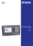
User’s Manual
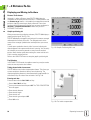
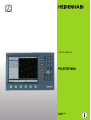
POSITIP 880
English (en)
6/2005
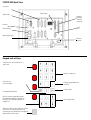
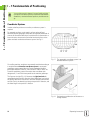
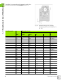
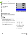
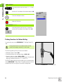
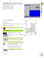
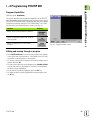
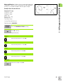
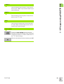
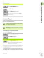
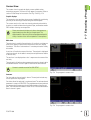
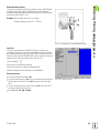
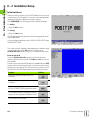
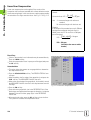
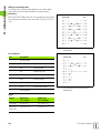
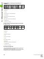
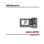
POSITIP 880 Back View
Axis ports
Edge finder
Parallel port
Auxiliary
Machine
Interface
connector
Ground
Serial
port
Power button
Main power input
Remote
console
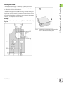
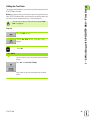
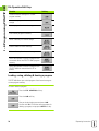
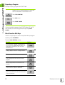
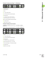
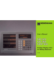
Keypad and soft keys
4 axis keys to select between X, Y
and Z axes
Numeric input keys
Clear entry or
error messages
Change negative/positive
value key
Confirm entry
Incremental dimensions
Keys for selecting operating mode
(for detailed description of these key
functions, see Operating Modes in
chapter I-2)
Soft keys - Row of keys under the screen
of the POSITIP whose functions vary
according to associated fields that appear
above them on the screen
Select entry fields
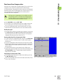
General Notes
General Notes
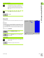
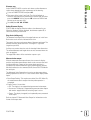
Software version
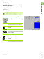
The software version of your unit is shown on the initial power up
screen and on the prompt bar after pressing the Help soft key.
This User's Manual covers the functions of the POSITIP
880 for both milling and turning applications. Basic
POSITIP 880 functions are covered in the first 4 chapters
of this manual. The turning section deals only with the
functions specific to turning applications.
About this manual
This manual is divided into two parts:
Part I: Operating Instructions
Part II: Technical Information
Operating Instructions
When using the POSITIP 880 in your work, you need only refer to the
Operating Instructions (Part I).
If you're new to POSITIP 880, you can use the operating instructions
as a step-by-step workbook. This part begins with a short introduction
to the basics of coordinate systems and position feedback, and
provides an overview of the available features. Each feature is
explained in detail, using an example which you can immediately try
out on the machine — so you won't get "lost" in the theory. As a
beginner you should work through all the examples presented.
If you're already familiar with POSITIP 880, you can use the
Operating Instructions as a comprehensive review and reference
guide.
Technical Information
If you are interfacing the POSITIP 880 to a machine or wish to use the
data interfaces, refer to the technical information in Part II.
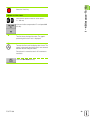
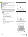
Dialog flowcharts
Dialog flowcharts are used for each example in this manual. They are
laid out as follows:
POSITIP 880
3
General Notes
PROMPT
KEY
This area explains the key function or work step. If
necessary, supplementary information will also be
included.
If there is an arrow at the end of the flowchart, this means that it
continues on the next page.
A perforated line indicates an alternative method of carrying out the
given function.
A prompt appears with some actions (not always) in the message bar
on the screen.
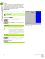
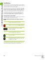
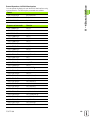
Important Notes in this Manual
Special green note boxes contain especially important information.
Please pay special attention to these notes. Neglecting this
information can result in e.g. functions not working in the desired way
or in causing damage to the workpiece or to the tool.
4
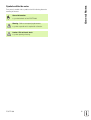
General Notes
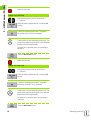
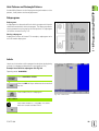
Symbols within the notes
Every note is marked with a symbol on the left informing about the
meaning of the note.
General Information
e.g. on the behavior of the POSITIP 880.
Warning – Refer to accompanying documents
e.g. when a special tool is required for a function.
Caution - Risk of electric shock
e.g. when opening a housing.
POSITIP 880
5
I Operating Instructions ..... 11
I – 1 Fundamentals of Positioning ..... 12
Coordinate Systems ..... 12
Setting the Datum ..... 13
Nominal Position, Actual Position and Distance-To-Go ..... 14
Absolute Workpiece Positions ..... 15
Incremental Workpiece Positions ..... 15
Position Encoders ..... 17
Reference Marks ..... 17
Angle Reference Axis ..... 18
I – 2 Working with POSITIP 880 – First Steps ..... 19
Power Up ..... 19
Before You Start ..... 19
Operating Modes ..... 21
On-Screen Operating Instructions (HELP Mode) ..... 22
Confirming Your Changes ..... 22
Messages ..... 23
Error messages ..... 23
Selecting the Unit of Measure ..... 24
Selecting the Angle Format ..... 24
Tool Table ..... 24
Calling the Tool Data ..... 25
I – 3 Actual Value ..... 26
Datum Setting: Approaching Positions and Entering Actual Values ..... 26
Probing Functions for Datum Setting ..... 28
Datum Setting with a Tool ..... 34
I – 4 Distance-To-Go ..... 36
Displaying and Moving to Positions ..... 36
I – 5 Milling Patterns ..... 43
Circle Pattern ..... 43
Linear Pattern ..... 46
Milling a Rectangle Pocket ..... 49
POSITIP 880
7
I – 6 Programming POSITIP 880 ..... 53
Program Capabilities ..... 53
Editing and moving through a program ..... 53
Programming Features ..... 54
Tool Call ..... 56
Datum Call ..... 57
Presets ..... 58
Hole Patterns and Rectangle Patterns ..... 59
Subprograms ..... 59
Labels ..... 59
Label Number ..... 60
Label Call ..... 60
Position Drill ..... 62
Milling a Line ..... 63
Milling an Arc ..... 64
Blend ..... 66
Chamfer ..... 68
File Operation Soft Keys ..... 70
Loading, saving, deleting & clearing a program ..... 70
Directories ..... 71
Importing a Program ..... 73
Exporting a Program ..... 74
Block Function Soft Keys ..... 74
I – 7 Executing a Program ..... 78
Program views ..... 80
Contour View ..... 81
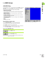
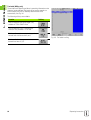
I – 8 INFO Screen ..... 83
JOB SETUP Menu ..... 83
Tool Table Usage ..... 85
Installation Menu ..... 92
Calculator ..... 92
Language ..... 95
Inch/MM ..... 95
8
I – 9 POSITIP 880 Turning Functions ..... 96
Power Up ..... 96
Fundamentals of Positioning ..... 97
Job Setup for Turning Applications ..... 98
Tool Table Usage ..... 99
Tool Offsetting ..... 102
NOTE/SET Function ..... 103
Datum Setting ..... 104
Taper Calculator ..... 104
Programming Turning Functions for POSITIP 880 ..... 106
Programming Features Soft Keys ..... 106
Multipass ..... 107
File Operation Soft Keys ..... 108
Block Function Soft Keys ..... 109
POSITIP 880
9
II Technical Information ..... 111
II – 1 Installation and Electrical Connection ..... 112
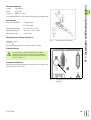
Items Supplied ..... 112
Mounting Location ..... 112
Installation ..... 112
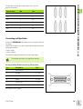
Connecting the Encoders ..... 114
Connecting an Edge Finder ..... 115
II – 2 Installation Setup ..... 116
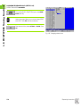
Initial switch-on ..... 116
General field/form navigation guide ..... 117
Axes Configuration ..... 117
Encoder Setup ..... 118
Error Compensation ..... 119
Linear Error Compensation ..... 120
Non-Linear Error Compensation ..... 121
Serial Port (X31) ..... 123
Parallel Port (X32) ..... 123
Protection ..... 124
Counter Settings ..... 124
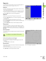
Diagnostics ..... 125
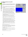
AMI (Auxiliary Machine Interface)(X51) (Optional) ..... 126
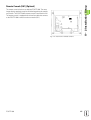
Remote Console (X61) (Optional) ..... 127
II – 3 Encoders and Measured Value Display ..... 128
Setting the display step with rotary encoders ..... 129
II – 4 Data Interface ..... 130
II – 5 Measured Value Output ..... 135
Examples of character output at the data interface ..... 135
II – 6 Specifications for Milling ..... 139
II – 7 Specifications for Turning ..... 141
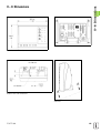
II – 8 Dimensions ..... 143
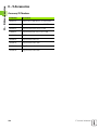
II – 9 Accessories ..... 144
Accessory ID Numbers ..... 144
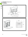
POSITIP 880 Mounting Instructions
Universal Mounting Arm
ld. Nr. 382 929-01 ..... 145
POSITIP 880 Mounting Instructions
Mounting base
ld. Nr. 382 892-01 ..... 146
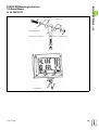
POSITIP 880 Mounting Instructions
Tilt/Swivel Mount
ld. Nr. 382 891-01 ..... 147
10
Operating Instructions
POSITIP 880
11
I – 1 Fundamentals of Positioning
I – 1 Fundamentals of Positioning
You can skip over this chapter if you are familiar with the
concepts of coordinate systems, incremental and absolute
dimensions, nominal and actual positions, and distance-togo.
Coordinate Systems
In order to define positions on a surface, a reference system is
required.
For example, positions on the earth's surface can be defined
absolutely by their geographic coordinates of longitude and latitude. In
contrast to the relative definition of a position that is referenced to a
known location, the network of horizontal and vertical lines on the
globe constitute an absolute reference system. See Fig. I.1.
Fig. I.1
The geographic coordinate system is an
absolute reference system
Fig. I.2
Designations and directions of the axes on a
milling machine
On a milling machine, workpieces are normally machined according to
a workpiece-based Cartesian coordinate system (a rectangular
coordinate system named after the French mathematician and
philosopher Renatus Cartesius, who lived from 1596 to 1650). The
Cartesian coordinate system is based on three coordinate axes
designated X, Y and Z which are parallel to the machine guideways.
The figure to the right (Fig. I.2) illustrates the right-hand rule for
remembering the three axis directions: the middle finger is pointing in
the positive direction of the tool axis from the workpiece toward the
tool (the Z axis), the thumb is pointing in the positive X direction, and
the index finger in the positive Y direction.
12
I Operating Instructions
The workpiece drawing (Fig. I.3) identifies a certain point on the
workpiece (usually a corner) as the absolute datum and perhaps one
or more other points as relative datums.
The datum setting procedure establishes these points as the origin of
the absolute or relative coordinate systems: The workpiece, which is
aligned with the machine axes, is moved to a certain position relative
to the tool and the display is set either to zero or to another appropriate
value (e.g., to compensate the tool radius).
Example:
Drawing with several relative datums (ISO 129 or DIN 406 Part 11,
Fig. 171)
Fig. I.3
POSITIP 880
The workpiece datum represents the origin
of the Cartesian coordinate system
13
I – 1 Fundamentals of Positioning
Setting the Datum
I – 1 Fundamentals of Positioning
Example: Coordinates of hole 1:
X =10 mm
Y = 5 mm
Z = 0 mm (hole depth: Z = – 5 mm)
The datum of the Cartesian coordinate system is located 10 mm from
hole 1 in the X axis and 5 mm from it in the Y axis. See Fig. I.4.
The KT Edge Finder from HEIDENHAIN, together with the
POSITIP 880's edge finding functions, facilitates finding and setting
datums.
Fig. I.4
Hole 1 defines the coordinatesystem
Fig. I.5
Nominal position S, actual position I and
distance-to-go R
Nominal Position, Actual Position and DistanceTo-Go
The position that the tool is to move to is called the nominal position
while the position of the tool at any given moment is called the actual
position. The distance from the nominal position to the actual position
is called the distance-to-go. See Fig. I.5.
Sign for distance-to-go
The distance-to go has a positive sign if the axis direction from the
actual towards the nominal position is negative.
The distance-to-go has a negative sign if the axis direction from the
actual towards the nominal position is positive.
14
I Operating Instructions
I – 1 Fundamentals of Positioning
Absolute Workpiece Positions
Each position on the workpiece is uniquely identified by its absolute
coordinates. See Fig. I.6.
Example: Absolute coordinates of position 1:
X = 20 mm
Y = 10 mm
Z = 15 mm
If you are drilling or milling a workpiece according to a workpiece
drawing with absolute coordinates, you are moving the tool to the
value of the coordinates.
Fig. I.6
Position 1 definition through absolute
coordinates
Fig. I.7
Positions 2 and 3 through incremental
coordinates
Incremental Workpiece Positions
A position can also be referenced to the preceding nominal position.
In this case the relative datum is always the last nominal position.
Such coordinates are referred to as incremental coordinates
(increment = increase). They are also called incremental or chain
dimensions (since the positions are defined as a chain of dimensions).
Incremental coordinates are designated with the prefix I.
Example: Incremental coordinates of position 3 referenced to position
2. See Fig. I.7
Absolute coordinates of position 2:
X = 10 mm
Y = 5 mm
Z = 20 mm
Incremental coordinates of position 3:
IX = 10 mm
IY = 10 mm
IZ = –15 mm
If you are drilling or milling a workpiece according to a drawing with
incremental coordinates, you are moving the tool by the value of the
coordinates.
POSITIP 880
15
I – 1 Fundamentals of Positioning
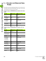
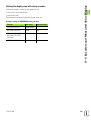
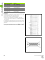
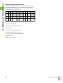
A coordinate list corresponding to this example is useful when
working in the operating mode: PROGRAMMING. See Fig. I.8
Fig. I.8
Coordinateorigin
Workpiece drawing with coordinate
dimensioning (ISO 129 or DIN 406 Part 11,
Fig. 179)
Dimensions in mm
Coordinates
Pos.
X1 X2
Y1 Y2
r
f
d
1
1
0
0
-
1
1.1
325
320
ø 120 H7
1
1.2
900
320
ø 120 H7
1
1.3
950
750
ø 200 H7
1
2
450
750
ø 200 H7
1
3
700
1225
ø 400 H8
2
2.1
-300
150
ø 50 H11
2
2.2
-300
0
ø 50 H11
2
2.3
-300
-150
ø 50 H11
3
3.1
250
0°
ø 26
3
3.2
250
30°
ø 26
3
3.3
250
60°
ø 26
3
3.4
250
90°
ø 26
3
3.5
250
120°
ø 26
3
3.6
250
150°
ø 26
3
3.7
250
180°
ø 26
3
3.8
250
210°
ø 26
3
3.9
250
240°
ø 26
3
3.10
250
270°
ø 26
3
3.11
250
300°
ø 26
3
3.12
250
330°
ø 26
16
I Operating Instructions
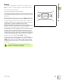
The position feedback encoders convert the movement of the
machine axes into electrical signals. The POSITIP 880 constantly
evaluates these signals and calculates the actual positions of the
machine axes, which it displays as a numerical value on the screen.
See Fig. I.9.
If there is an interruption in power, the calculated position will no
longer correspond to the actual position. When power is restored, you
can re-establish this relationship with the aid of the reference marks
on the position encoders and the POSITIP 880's reference mark
evaluation feature (REF).
Fig. I.9
Linear position encoder, here for the X axis
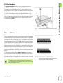
Reference Marks
The scales of the position encoders contain one or more reference
marks. When reference marks are crossed they can be used to define
an absolute position in an incremental system. If power is interrupted
this absolute position is lost and the relationship between the
reference mark and scale position is lost. The reference marks on the
position encoders and the POSITIP 880's reference mark evaluation
feature allows the unit to quickly re-establish this relationship again
when power is restored. See Fig. I.10.
When a reference mark is crossed over, it generates a signal which
identifies that position as the reference point. The POSITIP 880 uses
this reference point to restore the relationship between the scale
position and the display value which was last defined by setting the
datum.
If the position encoders feature distance-coded reference marks,
there are reference marks uniquely spaced along the length of the
scale. Crossing any two reference marks will restore the datum. Each
axis need only move a limited distance for linear encoders, and angle
for rotary encoders.
The datum setting cannot be restored from one power
cycle to the next if the reference marks were not crossed
before the datum was set.
POSITIP 880
Fig. I.10 Linear scales: with distance-coded
reference marks (upper illustration) and one
reference mark (lower illustration)
17
I – 1 Fundamentals of Positioning
Position Encoders
I – 1 Fundamentals of Positioning
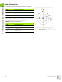
Angle Reference Axis
For angular positions, the following reference axes are defined:
Plane
Angle reference axis
XY
+X
YZ
+Y
ZX
+Z
Positive direction of rotation is counterclockwise if the working plane
is viewed in negative tool axis direction. See Fig. I.11.
Example: Angle in the working plane X / Y
Angle
Corresponds to the...
+ 45°
... bisecting line between +X and +Y
+/– 180°
... negative X axis
- 270°
... positive Y axis
18
Fig. I.11 Angle and the angle reference axis, e.g. in
the X / Y plane
I Operating Instructions
I – 2 Working with POSITIP 880 – First Steps
I – 2 Working with POSITIP 880 –
First Steps
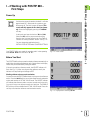
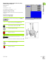
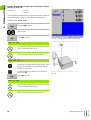
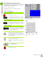
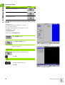
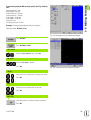
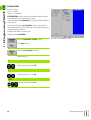
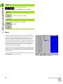
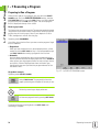
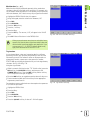
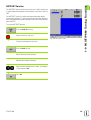
Power Up
Switch on the power (located on the back). It will take
approximately 25 - 30 seconds for system to start
after power up. The initial screen will appear (This
screen will only appear the first time you power
up). Select the language by pressing the LANGUAGE
soft key.
At this point you have the choice of MILL or TURN.
Select the MILL soft key to proceed with milling
functions the first time you power up. See Table of
Contents for turning functions section. See Fig. I.12.
You can change the application later in
INSTALLATION SETUP under COUNTER SETTINGS.
Your POSITIP 880 is now ready for operation and is in the operating
mode ACTUAL VALUE. Axis will show “NO REF”.
Fig. I.12 Initial screen
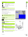
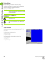
Before You Start
The POSITIP 880's reference mark evaluation feature automatically reestablishes the relationship between axis slide positions and display
values that you last defined by setting the datum.
If the axis encoder has reference marks, the NO REF indicator will
flash. See Fig. I.13. After crossing over the reference marks, the
indicator will stop flashing and change to REF.
Working without reference mark evaluation
You can also use the POSITIP 880 without crossing over the reference
marks. Press the NO REF soft key to exit the reference mark evaluation
routine and continue in ACTUAL VALUE mode. The NO REF indicator
will indicate that reference marks were not crossed over for that axis.
You can still cross over reference marks at a later time. The ENABLE
REF soft key will be available from ACTUAL VALUE mode. Press this
soft key to activate the reference mark evaluation routine.
Fig. I.13 Display before choosing NO REF
POSITIP 880
19
I – 2 Working with POSITIP 880 – First Steps
ENABLE REF function
The purpose of the ENABLE REF function, is to give the operator the
opportunity to either ignore the reference marks as they are crossed
over by disabling it, or finding reference marks when necessary by
enabling it. When the ENABLE REF soft key is pressed, the POSITIP 880
is ready to identify a reference mark. When the ENABLE REF soft key is
not depressed, POSITIP 880 will ignore all reference marks. When all
reference marks have been found, the ENABLE REF soft key will
disappear.
If an encoder is setup without reference marks, then the
REF indicator will not be displayed.
Once reference marks for all desired axes are established, press NO
REF soft key to cancel out of routine. You do not have to cross over the
reference marks of all the encoders, only those that you need.
If you do not cross over the reference marks, POSITIP 880
does not store the datum points. This means that it is not
possible to re-establish the relationship between axis slide
positions and display values after a power interruption
(switch-off).
Turn on power and press any key.
Cross over the reference marks (in any order).
Do not cross over the reference marks. Note: In this
case the relationship between axis slide position and
display value will be lost after a power interruption.
Press the NO REF soft key.
20
I Operating Instructions
I – 2 Working with POSITIP 880 – First Steps
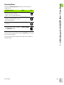
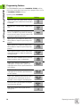
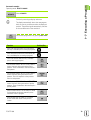
Operating Modes
Selecting the operating mode determines which functions are
available to you.
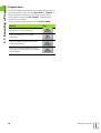
Available functions
Mode
Position display for workpiece
machining; Zero reset; Datum
setting – also with edge finder probe
ACTUAL VALUE
Distance-to-go display; hole
patterns; milling and drilling with tool
radius compensation
DISTANCE-TO-GO
Storage of work steps for small-lot
production
PROGRAMMING
Run programs previously created in
the PROGRAMMING mode
EXECUTE PROGRAM
Key
You can switch to another operating mode at any time by pressing the
key for the desired mode.
In the following examples requiring tool usage, refer to chapter I-8
under Job Setup.
POSITIP 880
21
I – 2 Working with POSITIP 880 – First Steps
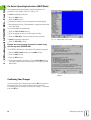
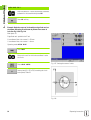
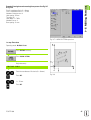
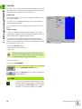
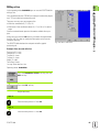
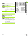
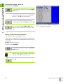
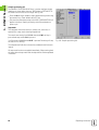
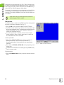
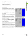
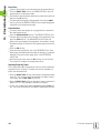
On-Screen Operating Instructions (HELP Mode)
The integrated operating instructions provide information and
assistance in any situation. See Fig. I.14 & Fig. I.15.
To call the operating instructions:
8
8
8
8
Press the INFO soft key.
Press the HELP soft key.
Information relevant to the current operation will be displayed.
Use the paging soft keys if the explanation is spread over more than
one screen page.
To view information on another topic:
8
8
8
Press the LIST OF TOPICS soft key.
Press the paging soft keys to scroll through the index.
Press the VIEW TOPIC soft key to select the item you need.
To leave the operating instructions:
8
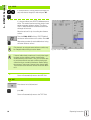
Fig. I.14 Index under HELP mode
Press the EXIT HELP soft key.
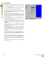
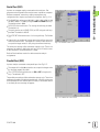
Example: On-screen operating instructions for datum setting
with the edge finder (CENTER LINE)
The CENTER LINE function is described in this manual on page 20.
8
8
From the ACTUAL VALUE mode, press the PROBE soft key.
Press the INFO soft key.
8
Press the HELP soft key.
8
To leave the operating instructions: Press the EXIT HELP soft key.
The screen returns to the screen with the SET DATUM form and
DRO display.
Fig. I.15 On-screen operating instructions for datum
setting
Confirming Your Changes
You must confirm your changes by pressing the ENT key for them to
become effective. The instruction sections of this manual will
occasionally give the command “Confirm your changes.” This means
press the ENT key.
22
I Operating Instructions
I – 2 Working with POSITIP 880 – First Steps
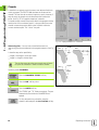
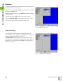
Messages
The Message bar messages will change color depending on the type
of information it is conveying: Normal messages will appear as gray
boxes with black text. Instructional messages will appear as blue
boxes with white text. Error messages will appear as red boxes with
white text.
Error messages
If an error occurs while you are working with POSITIP 880, the
Message bar will turn red and provide an explanation of what caused
the error.
To clear the error message:
8
Press the CE (Clear Entry) key.
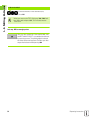
Critical error messages
Critical error messages mean that the operational
reliability of the POSITIP 880 has been impaired.
If a critical error occurs, a message box will appear in the middle of the
screen:
8
8
8
8
Take note of the error message displayed on the screen.
Switch off the power to the POSITIP 880.
Attempt to correct the problem with the power off.
If the critical error message recurs, notify your customer service
agency.
POSITIP 880
23
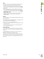
I – 2 Working with POSITIP 880 – First Steps
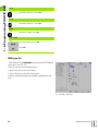
Selecting the Unit of Measure
Positions can be displayed and entered in millimeters or inches. If you
choose inches, INCH will be displayed on the status bar at the top of
the screen. See Fig. I.16.
To change the unit of measure:
8
8
8
Press the INFO soft key.
Press the INCH/MM soft key.
The unit of measure can also be set in JOB SETUP. Refer to Job
Setup, chapter I-8.
Fig. I.16 The MM indicator
Selecting the Angle Format
Angles – such as for a rotary table – can be displayed and entered
either as decimal degrees, degrees/minutes/seconds (DMS) or radian
values. Refer to Job Setup, chapter I-8 for instructions on setting angle
format.
Tool Table
The POSITIP 880’s tool table provides a convenient way to store
diameter and length offset information for each of the tools you
commonly use. You can enter up to 99 tools.
Before you start workpiece machining, select the tool you are using
from the tool table. POSITIP 880 will then take into account the
entered diameter and length of the tool.
The tool length is the difference in length ∆L between the tool and the
reference tool. The reference tool is indicated by T1 in Fig. I.17.
Sign for the length difference ∆L
If the tool is longer than the reference tool: ∆L > 0 (+)
If the tool is shorter than the reference tool: ∆L < 0 (–)
Refer to Job Setup for entering a tool into the tool table.
Fig. I.17 Tool length and diameter
24
I Operating Instructions
I – 2 Working with POSITIP 880 – First Steps
Calling the Tool Data
The lengths and diameters of your tools must first be entered into the
POSITIP 880's tool table.
Before you start machining, select the tool you are using from the tool
table. POSITIP 880 then takes into account the stored tool data when
you work with tool compensation (e.g., with hole patterns).
You can also call the tool data with the command TOOL
CALL in a program.
Tool call
Press the INFO soft key.
Then the JOB SETUP soft key. (Tool table is highlighted).
Press ENT.
TOOL NUMBER
Cursor to the tool you want or enter the tool number
directly.
Press USE, then USE NEW SETTINGS.
View status bar to verify the proper tool has been
called.
POSITIP 880
25
I – 3 Actual Value
I – 3 Actual Value
Datum Setting: Approaching Positions and
Entering Actual Values
The easiest way to set datum points is to use the POSITIP 880's
probing functions – regardless of whether you probe the workpiece
with the HEIDENHAIN KT Edge Finder or with a tool. Description of
the probing functions: See "Probing Functions for Datum Setting" on
page 28
Of course, you can also set datum points in the conventional manner
by touching the edges of the workpiece one after the other with the
tool and entering the tool positions as datum points (see examples
following this page).
The datum table can hold up to 99 datum points. In most cases this
will free you from having to calculate the axis travel when working
with complicated workpiece drawings containing several datums.
Datum settings are performed in the ACTUAL VALUE operating mode
and define the relationships between the axis positions and the
display values. If necessary, the datum table’s values may be changed
by entering a value directly.
See Job Setup for setting the datum value directly.
Datum selection (Mill only)
In ACTUAL VALUE mode, the Up/Down arrow keys may be used to
select the next or previous datum number.
Tool selection (Turn only)
In ACTUAL VALUE mode, the Up/Down arrow keys may be used to
select the next or previous tool number.
26
I Operating Instructions
I – 3 Actual Value
Example: Setting a workpiece datum without the probing
function. See Fig. I.18 & Fig. I.19.
Working plane: XY
Tool axis: Z
Tool diameter: D = 3 mm
Axis sequence in this example: X - Y - Z
Preparation: Calling the tool data
Select the tool data for the tool which you are using to touch the
workpiece.
Preparation: Select the datum
Operating mode: ACTUAL VALUE
From ACTUAL VALUE mode, press the DATUM soft
key.
Fig. I.18 SET DATUM form
Cursor will be in the DATUM NUMBER field.
Enter the datum number and press ENT.
Touch the workpiece at edge 1.
Select the X axis key.
DATUM SETTING X
Enter the position of the tool center (X = – 1.5 mm)
and
transfer the X-coordinate of the datum and press ENT.
Fig. I.19
Touch the workpiece at edge 2.
Select the Y axis key.
POSITIP 880
27
I – 3 Actual Value
DATUM SETTING Y
Enter the position of the tool center (Y = – 1.5 mm)
and
transfer the Y-coordinate of the datum and press ENT.
Touch the workpiece surface.
Select the Z axis key.
DATUM SETTING Z = + 0
Enter the position of the tool tip (Z = 0 mm) and
transfer the Z-coordinate of the datum. Press USE.
Probing Functions for Datum Setting
It is particularly easy with a HEIDENHAIN KT 130 Edge Finder (Fig.
I.20).
During probe functions, the display freezes with the
location of the edge, centerline, or circle center.
The following probing soft key functions are available:
Workpiece edge as datum: EDGE
Centerline between two workpiece edges: CENTER LINE
Center of a hole or cylinder: CIRCLE CENTER
With Circle Center, the hole must be in a main plane. The three main
planes are formed by the axes X / Y, Y / Z and Z / X.
The POSITIP 880's probing functions enable you to set datum points
with a HEIDENHAIN KT Edge Finder. The probing functions are also
available when you are using a tool instead of an edge finder.
Fig. I.20 The HEIDENHAIN KT 130 Edge Finder
28
I Operating Instructions
I – 3 Actual Value
Datum setting with the edge finder
Preparation: Enter the stylus diameter and select the datum
8 Press the INFO soft key.
8 Press JOB SETUP, then cursor to EDGE FINDER and press ENT.
8 Enter the diameter of the edge finder stylus and confirm with ENT.
8 Enter the desired length and confirm with ENT.
8 Enter the desired unit of measurement (inch/mm).
8 Press USE, then USE NEW SETTINGS.
In all probing functions, POSITIP 880 takes into account the entered
stylus diameter.
To abort the probing function
While the probing function is active, POSITIP 880 displays the CANCEL
soft key. Choose this soft key to return to the opening state of the
selected probing function.
POSITIP 880
29
I – 3 Actual Value
Example: Probe workpiece edges, and set the corner as a datum.
See Fig. I.21 & Fig. I.22.
Datum axis:
X = 0 mm
Y = 0 mm
The coordinates of the datum can be set by probing edges or surfaces
and capturing them as datums as described on the next page.
Operating mode: ACTUAL VALUE
Press the PROBE soft key.
Cursor to axis.
Press EDGE soft key.
Fig. I.21 Form for setting datum using an edge
PROBE IN X AXIS
Move the edge finder toward the workpiece until the
LEDs on the edge finder light up.
Retract the edge finder from the workpiece.
ENTER VALUE FOR X + 0
0 is offered as a default value for the coordinate. Enter
the desired coordinate for the workpiece edge, for
example X = 0 mm and
set the coordinate as a datum for this workpiece
edge. Press ENT.
Fig. I.22
Press EDGE soft key.
PROBE IN Y AXIS
Move the edge finder toward the workpiece until the
LEDs on the edge finder light up.
Retract the edge finder from the workpiece.
30
I Operating Instructions
I – 3 Actual Value
ENTER VALUE FOR Y + 0
0 is offered as a default value for the coordinate. Enter
the desired coordinate for the workpiece edge, for
example Y = 0 mm and
set the coordinate as a datum for this workpiece
edge. Press ENT.
Press USE soft key.
Example: Set centerline between two workpiece edges as datum.
See Fig. I.23 & Fig. I.24.
The position of the centerline M is determined by probing the edges 1
and 2.
The centerline is parallel to the Y axis.
Desired coordinate of the centerline: X =0 mm
Operating mode: ACTUAL VALUE
Spacing between edges is displayed on the message bar
when using the probe centerline feature.
Press PROBE.
Cursor to the axis for which the coordinate is to be
set: X axis.
Fig. I.23 Setting centerline between two edges
Press CENTER LINE.
1. PROBE 1ST EDGE IN X
Move the edge finder toward workpiece edge 1 until
the LEDs in the edge finder light up.
2. PROBE 1ST EDGE IN X
Move the edge finder toward workpiece edge 2 until
the LEDs in the edge finder light up. The distance
between the edges is displayed on the message bar.
Fig. I.24
Retract the edge finder from the workpiece.
POSITIP 880
31
I – 3 Actual Value
ENTER VALUE FOR X
Enter coordinate (X = 0 mm) and transfer coordinate
as datum for the centerline and press ENT.
Press USE soft key.
Example: Probe the center of a hole with an edge finder and set
the datum. Offsetting X-axis datum by 50 mm from center of
hole. See Fig. I.25 & Fig. I.26.
Main plane: XY
Edge finder axis: parallel to the Z axis
X coordinate of the circle center: X = 50 mm
Y coordinate of the circle center: Y = 0 mm
Operating mode: ACTUAL VALUE
Press PROBE.
Cursor to the axis for which the coordinate is to be
set: X axis.
Press CIRCLE CENTER.
Fig. I.25 Setting the center of a hole
Select plane (X/Y, Y/Z or Z/X) containing the circle
(main plane): Plane XY
Fig. I.26
32
I Operating Instructions
I – 3 Actual Value
PROBE 1ST POINT IN X/Y
Move edge finder towards first point 1 on the
circumference until the LEDs on the edge finder light
up.
Retract edge finder from bore hole wall.
Probe two additional points on the circumference in
the same manner. Further instructions appear on the
screen. See Prompt bar for measured diameter.
ENTER CENTER POINT X
X = 50
Enter the first coordinate (X = 50 mm) and
transfer coordinate as datum for the circle center and
press ENT.
ENTER CENTER POINT Y
Y = 0
Accept default entry Y = 0 mm. Press ENT. Press USE.
POSITIP 880
33
I – 3 Actual Value
Datum Setting with a Tool
Even if you use a tool or non-electrical edge finder to set datum points,
you can still use POSITIP 880's probing functions described under the
section “Datum setting with the Edge Finder.” EDGE, CENTER LINE
and CIRCLE CENTER. See Fig. I.27 & Fig. I.28.
Preparation: Enter the tool diameter and select the datum
8 Press INFO.
8 Press the JOB SETUP soft key.
8 Select the TOOL TABLE form by pressing ENT.
8 Cursor to the tool you will use to set the datum.
8 Press USE and then USE NEW SETTINGS.
Example: Probe workpiece edge and set edge as datum
Datum axis: X =0 mm
Tool diameter D = 3 mm
Fig. I.27 Setting datum using an edge
Operating mode: ACTUAL VALUE
Press PROBE.
Cursor to the axis for which the coordinate is to be
set: X axis.
Press EDGE soft key.
PROBE IN X
Touch workpiece edge
Store the position of the edge by pressing the NOTE
soft key.
Fig. I.28
Retract the tool from the workpiece.
34
I Operating Instructions
I – 3 Actual Value
ENTER VALUE FOR X
Enter coordinate of the tool center
(X = -1.5 mm) and
transfer coordinate as datum for the center line and
press USE soft key.
POSITIP 880
35
I – 4 Distance-To-Go
I – 4 Distance-To-Go
Displaying and Moving to Positions
Distance-To-Go feature
Although it is often sufficient to have POSITIP 880 display the
coordinates of the actual position of the tool, it is usually better to use
the distance-to-go feature — this enables you to approach to nominal
positions simply by traversing to display value zero. Even when
working with the distance-to-go feature you can enter coordinates in
absolute or incremental dimensions. Make sure you are in
DISTANCE-TO-GO mode.
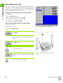
Graphic positioning aid
When you are traversing to display value zero, POSITIP 880 displays a
graphic positioning aid. See Fig. I.29.
POSITIP 880 displays the graphic positioning aid in a narrow rectangle
underneath the currently active axis. Two triangular marks in the
center of the rectangle symbolize the nominal position you want to
reach.
A small square symbolizes the axis slide. An arrow indicating the
direction appears in the square while the axis is moving. You can easily
tell whether you are moving towards or away from the nominal
position. Note that the square does not begin to move until the axis
slide is near the nominal position.
Fig. I.29 Graphic Positioning Aid in use
Refer to the JOB SETUP menu to setup the graphic positioning aid.
Tool Selection
In DISTANCE-TO-GO mode, the up/down arrow keys may be used to
select the next or previous tool number
Taking the tool radius into account
POSITIP 880 has a tool radius compensation feature. This allows you
to enter workpiece dimensions directly from the drawing. The
displayed remaining distance is then automatically lengthened (R+) or
shortened (R–) by the value of the tool radius. See Fig. I.30.
Entering tool data
Enter tool data with the TOOL TABLE soft key.
8
8
8
8
8
8
8
Choose TOOL TABLE soft key.
Cursor to the desired tool and press ENT. The TOOL DESCRIPTION
form will appear.
Enter the tool diameter.
Enter the tool length.
Enter the tool unit.
Enter the tool type and press ENT.
Press USE twice.
Fig. I.30 Tool radius compensation
36
I Operating Instructions
I – 4 Distance-To-Go
Example: Milling a shoulder by traversing to display value zero
The coordinates are entered as absolute dimensions; the datum is the
workpiece zero. See Fig. I.31 & Fig. I.32.
Corner 1: X = 0 mm / Y = 20 mm
Corner 2: X = 30 mm / Y = 20 mm
Corner 3: X = 30 mm / Y = 50 mm
Corner 4: X = 60 mm / Y = 50 mm
Fig. I.31 Single cycle preset
Operating mode: DISTANCE-TO-GO
Preparation:
8
8
8
Enter the tool data.
Pre-position the tool to an appropriate location (such as X = Y = -20
mm).
Move the tool to milling depth.
Select the Y axis key.
NOMINAL POSITION VALUE
Enter nominal position value for corner point 1:
Y = 20 mm and
select tool radius compensation R + with TOOL COMP
(R+) soft key.
Fig. I.32
Transfer the nominal position value by pressing USE.
The graphic positioning aid for the Y axis is displayed.
Traverse the Y axis until the display value is zero. The
square in the graphic positioning aid is now centered
between the two triangular marks.
Once the axis is moved to zero the axis value is
incremented to axis value in the next block.
Press the NEXT BLOCK soft key to advance.
POSITIP 880
37
I – 4 Distance-To-Go
Select the X axis key.
NOMINAL POSITION VALUE
Enter nominal position value for corner point 2:
Y = +30 mm,
select tool radius compensation R – and press USE
soft key.
Transfer the nominal position value. The graphic
positioning aid for the X axis is displayed.
Traverse the X axis until the display value is zero. The
square in the graphic positioning aid is now centered
between the two triangular marks.
Once the axis is moved to zero it will increment to
next block.
Press the NEXT BLOCK soft key.
Select the Y axis key.
NOMINAL POSITION VALUE
Enter nominal position value for corner point 3:
Y = +50 mm,
select tool radius compensation R + and press USE
soft key.
Transfer the nominal position value. The graphic
positioning aid for the Y axis is displayed.
Traverse the Y axis until the display value is zero. The
square in the graphic positioning aid is now centered
between the two triangular marks.
Once the axis is moved to zero it will increment to
Next Block.
Press the NEXT BLOCK soft key.
38
I Operating Instructions
I – 4 Distance-To-Go
Select the X axis key.
NOMINAL POSITION VALUE
Enter nominal position value for corner point 4:
Y = +60 mm,
select tool radius compensation R + and press USE
soft key.
Transfer the nominal position value. The graphic
positioning aid for the X axis is displayed.
Traverse the X axis until the display value is zero. The
square in the graphic positioning aid is now centered
between the two triangular marks.
Once the axis is moved to zero it will increment to
next block.
Press the NEXT BLOCK soft key.
POSITIP 880
39
I – 4 Distance-To-Go
Example: Drilling by traversing to display value zero
Enter the coordinates in incremental dimensions. These are indicated
in the following (and on the screen) with a preceding I. The datum is
the workpiece zero. See Fig. I.33 & Fig. I.34.
Hole 1 at: X = 20 mm / Y = 20 mm
Distance from hole 2 to hole 1: IX = 30 mm / IY = 30 mm
Hole depth: Z = –12 mm
Operating mode: DISTANCE-TO-GO
NOMINAL POSITION VALUE
Select an axis key: X axis.
Enter nominal position value for hole 1: X = 20 mm
and press ENT. Cursor will move to the Y axis field.
Fig. I.33 Drilling example
NOMINAL POSITION VALUE
Enter nominal position value for hole 1: Y = 20 mm
and press ENT. Cursor will move to the Z axis field.
NOMINAL POSITION VALUE
Enter the nominal position value for the hole depth:
Z = –12 mm The graphic positioning aid for the Z axis
is displayed. Press USE soft key.
Pre-position the drill over the first hole. Traverse Z
axis until the display value is zero. The square in the
graphic positioning aid is now centered between the
two triangular marks.
Fig. I.34
Retract the drill in the tool axis (Z).
Once the axis is moved to zero it will increment to
next block.
Press the NEXT BLOCK soft key.
Select an axis key: X axis.
40
I Operating Instructions
I – 4 Distance-To-Go
NOMINAL POSITION VALUE
Enter nominal position value for hole 2: Y = 30 mm,
mark your input as an incremental dimension, press I
hard key.
Select tool radius compensation R0 by pressing TOOL
COMP (R0) soft key.
Press USE. The graphic positioning aid for the X axis
is displayed.
Traverse the X axis until the display value is zero. The
square in the graphic positioning aid is now centered
between the two triangular marks.
Once the axis is moved to zero it will increment to
next block.
Press the NEXT BLOCK soft key.
Select the Y axis key.
POSITIP 880
41
I – 4 Distance-To-Go
NOMINAL POSITION VALUE
Enter nominal position value for hole 2: Y = 30 mm,
mark your input as an incremental dimension, press I
hard key.
Select tool radius compensation R0 by pressing TOOL
COMP (R0) soft key.
Press USE. The graphic positioning aid for the Y axis
is displayed.
Traverse the Y axis until the display value is zero. The
square in the graphic positioning aid is now centered
between the two triangular marks.
Once the axis is moved to zero it will increment to
next block.
Press the NEXT BLOCK soft key.
Select the Z axis key.
NOMINAL POSITION VALUE
Enter the nominal position value for the hole depth:
Z = –12 mm
Press USE soft key. The graphic positioning aid for the
Z axis is displayed.
Drill hole 2: Traverse Z axis until the display value is
zero. The square in the graphic positioning aid is now
centered between the two triangular marks.
Retract the drill in the tool axis (Z).
Once the axis is moved to zero the operation is
complete.
Press the NEXT BLOCK soft key.
42
I Operating Instructions
I – 5 Milling Patterns
I – 5 Milling Patterns
This chapter describes the hole pattern functions CIRCLE PATTERN,
LINEAR PATTERN, RECTANGLE POCKET.
In the operating mode DISTANCE-TO-GO, use the soft keys to select the
desired hole pattern function or pocket milling, and enter the required
data. This data can usually be taken from the workpiece drawing (e.g.
hole depth, number of holes, dimensions of the pocket, etc.).
With hole patterns, the POSITIP 880 then calculates the positions of
all the holes and displays the pattern graphically on the screen. With
pocket milling, it calculates all of the traverse paths for the roughing
out of the pocket. The graphic positioning aid appears when you begin
execution, enabling you to position simply by traversing to display
value zero.
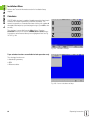
Circle Pattern
Automatic advance function
Once you have moved the table into position and machined to depth,
the POSITIP 880 will automatically advance. You can also manually
advance by pressing the NEXT HOLE soft key.
POSITIP 880 will not automatically advance if the depth is
set to THRU.
Information required:
Pattern type (full or half)
Holes (no. of)
Center (center of circle pattern in pattern plane)
Radius (defines radius of the circle pattern)
Start angle (angle of 1st hole in the pattern)
Step angle (optional: this only applies if creating a circle segment.)
Depth (the target depth for drilling in the tool axis)
POSITIP 880 calculates the coordinates of the holes which you then
move to simply by traversing to display value zero. The graphic
positioning aid is available for all moving axes.
A circle pattern is executed as a series of presets to the hole location
in the pattern plane and the drill depth.
POSITIP 880
43
I – 5 Milling Patterns
Functions for drilling
Function
Soft key
Press to go to previous hole.
Press to manually advance to the next hole.
Press to end drilling.
Example: Enter data and execute a circle pattern. See Fig. I.35 &
Fig. I.36.
Holes (no. of): 4
Coordinates of center: X = 50 mm / Y = 50 mm
Bolt circle radius: 20 mm
Start angle: Angle between X axis and first hole: 30°
Hole depth: Z = – 5 mm
1st step: Enter data
Operating mode: DISTANCE-TO-GO
Press FEATURES soft key.
Press CIRCLE PATTERN soft key.
Fig. I.35 CIRCLE PATTERN form
Begin inputting data.
PATTERN TYPE
Enter the type of circle pattern (full).
Press ENT.
HOLES
Enter the number of holes (4).
Press ENT.
Fig. I.36 Circle pattern graphic
44
I Operating Instructions
I – 5 Milling Patterns
CENTER
Enter the X and Y coordinates of the circle center
(both 50).
Press ENT.
RADIUS
Enter the radius of the circle pattern (20).
Press ENT.
START ANGLE
Enter the start angle (30°).
Press ENT.
DEPTH
Enter the depth of each hole (-5.0).
Press ENT.
When in TOOL field enter the TOOL TABLE and select the
desired tool.
POSITIP 880
8
Press USE soft key to begin step.
8
Pressing the VIEW () soft key will toggle through the
different views of the pattern (Graphic, etc.).
45
I – 5 Milling Patterns
2nd step: Drill
Move to hole:
Traverse each coordinate of the working plane to
display value zero.
Drill:
Traverse to display value zero in the tool axis. When
you have reached required depth, it will automatically
advance to the coordinates of the next hole.
After drilling, retract the drill in tool axis.
Press the NEXT HOLE soft key.
Continue to drill the remaining holes in the same way.
When pattern is complete, press the END soft key.
Linear Pattern
Information required:
First hole (1st hole of the pattern)
Holes per row (number of holes in each row of pattern
Hole spacing (the spacing or offset between each hole in the row)
Angle (the angle or rotation of the pattern)
Depth (the target depth for drilling in the tool axis)
Number of rows (number of rows in the pattern)
Row spacing (the spacing between each row of the pattern)
POSITIP 880 calculates the coordinates of the holes which you then
move to simply by traversing to display value zero.
The graphic positioning aid is available for all moving axes.
The graphic enables verification of the hole pattern before you start
machining. It is also useful when:
selecting holes directly
executing holes separately
skipping holes
46
I Operating Instructions
I – 5 Milling Patterns
Example: Entering data and executing linear pattern. See Fig. I.37
& Fig. I.38.
First X coordinate of hole: X = 20 mm
First Y coordinate of hole: Y = 15 mm
Number of holes per row: 4
Hole spacing: 10 mm
Tilt angle: 18°
Hole depth: Z = THRU
Number of rows: 3
Row spacing: 12 mm
Fig. I.37 LINEAR PATTERN input form
1st step: Enter data
Operating mode: DISTANCE-TO-GO
Press FEATURES soft key.
Press LINEAR PATTERN.
Begin data entry.
FIRST HOLE X AND Y
Enter the coordinates of first hole (X = 20 mm).
Press ENT.
Fig. I.38
Y = 15 mm.
Press ENT.
POSITIP 880
47
I – 5 Milling Patterns
HOLES PER ROW
Enter the number of holes per row (4). Press ENT.
HOLE SPACING
Enter the space between holes (10).
Press ENT.
ANGLE
Enter the angle of rotation (18°).
Press ENT.
DEPTH
Enter the depth for drilling (THRU).
Press ENT.
NUMBER OF ROWS
Enter the number of rows (3).
Press ENT.
ROW SPACING
Enter the spacing between rows (12).
Press ENT.
When in TOOL field enter the TOOL TABLE and select the
desired tool.
Press USE.
Press the VIEW () soft key to see graphic.
48
I Operating Instructions
I – 5 Milling Patterns
2nd step: Drill
Start linear hole pattern function.
Move to hole:
Traverse each coordinate of the working plane to
display value zero.
Drill:
Traverse to display value zero in the tool axis.
After drilling, retract the drill in tool axis.
Press the NEXT HOLE soft key.
Continue to drill the remaining holes in the same way.
When pattern is complete, press the END soft key.
Milling a Rectangle Pocket
In the operating mode DISTANCE-TO-GO you can use the POSITIP 880
for milling a rectangle pocket.
The information for rectangle pocket milling can also be written to a
machining program as a cycle.
Select the cycle with the RECTANGLE POCKET soft key, and enter the
required data. This data can usually be taken quite easily from the
workpiece drawing (e.g. the axis size and the depth of the pockets).
The POSITIP 880 calculates the rough-out paths and offers graphic
positioning aid.
Finish allowance
The amount of material to be left for machining on the last pass around
the pocket.
POSITIP 880
49
I – 5 Milling Patterns
Rectangle pocket milling in programs
The POSITIP 880 makes the roughing out of rectangle pockets simple:
You just enter the dimensions for the pocket, and the POSITIP 880
calculates the rough-out paths.
Execution of cycle
The execution of the cycle is represented in the figures to the right.
Step 1:
The POSITIP 880 gives the distances-to-go for positioning the tool at
the starting position A: First in the tool axis, and then in the machining
plane to the center of the pocket.
Step 2:
Roughing out the pocket in accordance with the path indicated in the
diagram climb milling (see Step 2). In the working plane the stepover
is no greater than the radius of the current tool. The stepover distance
of the last pass around the pocket is equal to the finish allowance. The
operator chooses the appropriate pecking depth in the tool axis.
Step 1 in rectangle pocket
Step 3:
This procedure repeats itself until the entered depth B is reached.
Input into cycle for RECTANGLE POCKET
Starting position
(enter absolute value, referenced to datum)
End depth
(enter absolute value, referenced to datum)
Center in X
Center of the pocket in the main axis of the working plane.
Center in Y
Center of the pocket in the secondary axis of the working plane.
Size length in X
Length of the pocket in the direction of the main axis.
Size length in Y
Length of the pocket in the direction of the secondary axis.
Direction
(counter-clockwise or clockwise)
Finish allowance
Finishing allowance in the working plane.
Step 2 in rectangle pocket
Step 3 in rectangle pocket
50
I Operating Instructions
I – 5 Milling Patterns
Programming example: Mill rectangle pocket. See Fig. I.39 & Fig.
I.40.
Starting position: 2 mm
Milling depth: –20 mm
Pocket center in X: 50 mm
Pocket center in Y: 40 mm
Side length in X: 80 mm
Side length in Y: 60 mm
Direction: CCW
Finishing allowance: 0.5 mm
Example: Entering rectangle pocket data into a program
Operating mode: DISTANCE-TO-GO
Fig. I.39 Rectangle pocket programming example
Press FEATURES.
Press RECTANGLE POCKET.
START DEPTH
Enter the start depth (2 mm). Press ENT.
END DEPTH
Enter the end depth (- 20 mm).
Press ENT.
Fig. I.40 Rectangle pocket programming graphic
CENTER
Enter the X and Y dimensions for the pocket center.
Press ENT.
SIZE
Enter the X and Y dimensions for the side.
Press ENT.
DIRECTION
Enter the direction of rotation (counter-clockwise).
Press ENT.
POSITIP 880
51
I – 5 Milling Patterns
FINISH ALLOWANCE
Enter the amount of finish allowance (0.5).
Press ENT.
When you cursor to the TOOL field, press TOOL TABLE soft
key. Select tool and press USE. Tool will enter into the
TOOL field.
2nd step: Mill a rectangle pocket
After you have entered all of the required data, start
the RECTANGLE POCKET cycle and position the axes
by traversing to zero. The pecking depth in the tool
axis does not have to be preset. End the cycle after
the pocket has been milled pressing END.
52
I Operating Instructions
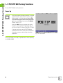
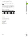
I – 6 Programming POSITIP 880
I – 6 Programming POSITIP 880
Program Capabilities
Operating mode: PROGRAMMING
This section describes the programming capabilities of the POSITIP
880. The programs can be edited in program memory and executed in
the EXECUTE PROGRAM mode. The operator can load, save or delete
a program from internal storage in FILE OPERATIONS. The CLEAR
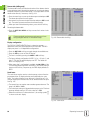
function clears the current program in memory. See Fig. I.41.
Function
Soft key
Allows access to all programming features.
Allows the operator to load, save, delete or
clear a program.
Allows the operator access to all block
functions.
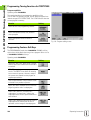
Fig. I.41 Program function screen
Editing and moving through a program
Press Up/Down Arrow keys to move the program block highlight
cursor to the next or previous block. The highlight cursor will wrap
around the first and last blocks in the program.
To move to a specific block number in the current program, enter a
number and press ENT.
To insert a new step in the current program, press PROGRAM FEATURES
soft key and select the desired block. The block is inserted above
the block currently highlighted.
To edit the block currently highlighted, press the ENT key.
To delete the block currently highlighted from the program, press
the CE key.
POSITIP 880
53
I – 6 Programming POSITIP 880
Programming Features
The PROGRAMMING mode has a PROGRAMMING FEATURES soft key
which shows all the blocks that can go into a program. Below is a list
of PROGRAMMING FEATURES soft keys.
Operating mode: PROGRAMMING
Function
Soft key
Opens the TOOL CALL block which is used to
select a specific tool number from the tool table
at run-time.
DATUM CALL is used to select a datum at runtime.
PRESET is used to locate a target position on
an axis. The PRESET form allows for entering
one or more axis values. Each axis value will be
entered as a separate preset block.
Opens CIRCLE PATTERN form. Refer to the
Milling Patterns chapter for performing circle
patterns.
Opens LINEAR PATTERN form. Refer to the
Milling Patterns chapter for performing linear
patterns.
Opens the RECTANGLE POCKET form. Refer
to the Milling Patterns chapter for performing
rectangle pockets.
Opens the LABEL NUMBER form to mark the
beginning and the end of a subprogram
LABEL CALL (REPEAT) is used to call a
subprogram 1 or more times. It allows the
subprogram to be offset a specified amount on
each iteration.
LABEL CALL (Rotate) allows blocks within a
subprogram to be rotated a specified amount
on each iteration.
LABEL CALL (MIRROR) allows blocks within a
subprogram to be inverted over an axis to
represent a mirror image of that subprogram.
POSITION DRILL soft key opens the program
form for position drill jobs.
LINE soft key opens the program form for
milling a line.
54
I Operating Instructions
I – 6 Programming POSITIP 880
Function
Soft key
ARC soft key opens the program form for
milling an arc.
BLEND soft key opens the program form and
NORMAL ARC, INVERTED ARC and CLOSED
CONTOUR soft keys for performing a blend.
CHAMFER soft key opens the program form
and the CLOSED CONTOUR soft key to create
a chamfer.
MORE soft key allows the operator to toggle
through the different soft keys rows.
Some programming features provided by the Positip 880,
such as Arcs, Blends and Chamfers, are not easily
machined on a manually operated machine. These tool
paths require two axes with simultaneously controlled
motion. The Positip 880’s Contour View function provides
a graphical method for the operator to approximate these
tool paths. See "Contour View" on page 81for details
regarding this function.
POSITIP 880
55
I – 6 Programming POSITIP 880
Tool Call
The TOOL CALL is used to select a specific tool number from the tool
table at run-time, for instance during a program. The block specifies a
tool number and an optional tool axis. See Fig. I.42.
Calling a tool
Refer to Job Setup for how to enter the length and diameter of your
tools in the tool table.
The TOOL CALL command automatically pulls the tool length and
diameter from the tool table.
You may define the tool axis for the program run in the TOOL CALL
block.
Tool axis setting
A tool axis is selected to define the machining plane. Tool radius
compensation is applied to the axes forming the machining plane. Tool
length compensation is applied along the tool axis.
For example, a horizontal boring machine may have machining
features such as hole patterns located in the YZ plane. The boring
operations are performed in the X axis. For this configuration, the tool
axis would be set to the X axis.
Fig. I.42 TOOL CALL form
Press the TOOL AXIS soft key.
Select the tool axis with soft key.
Press USE.
When you execute a tool call block with a new tool axis,
this tool axis will remain in effect until you select another
from the tool table or another tool call block.
To perform a tool call
Operating mode: PROGRAMMING
Press the PROGRAMMING FEATURES soft key.
Select the TOOL CALL soft key. The cursor defaults to
the NUMBER field.
TOOL NUMBER
The tool number defaults to the previous tool block’s
number. Enter the desired value by using the numeric
key pad or press the TOOL TABLE soft key. (The SIZE
and TOOL TYPE fields are read only.) Press ENT.
56
I Operating Instructions
I – 6 Programming POSITIP 880
TOOL AXIS (OPTIONAL)
Entering the tool axis (such as Z) is optional. It is used
to set the tool axis at run-time. An axis may be
selected by using the axis (X, Y, Z) soft keys. Press
ENT. The program contains the tool call block TOOL
CALL 1 Z.
Choose CE to clear any tool axis selection.
Press USE.
Datum Call
The DATUM CALL block is used to select a datum at run-time. See Fig.
I.43.
Datum call
The POSITIP 880 can store up to 99 datums in a datum table. You can
call a datum point from the datum table during a program run by simply
pressing the DATUM CALL soft key and entering the block DATUM XX.
This automatically calls the datum point entered for XX during program
run.
Operating mode: PROGRAMMING
Press the PROGRAMMING FEATURES soft key.
Select the DATUM CALL soft key. Call a datum point
from the table.
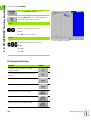
Fig. I.43 DATUM CALL form
DATUM NUMBER
Enter the datum number (such as 5). Press USE. Input
range: 0 to 99.
DATUM #5 will appear within the block.
POSITIP 880
57
I – 6 Programming POSITIP 880
Presets
The operator uses the PRESET function to establish a nominal position
on an axis to which to move. Use the PRESET form to enter the
desired preset value. The PRESET form allows for entering one or
more axis presets. However, multiple axis presets are entered into the
program as separate preset blocks. See Fig. I.44.
Entering a Preset
An axis preset involves entering a target value, selecting a preset type
(ACT or INC), and selecting a tool offset.
If the PRESET soft key is used, the cursor defaults to the
first axis field.
Operating mode: PROGRAMMING
Press the PROGRAMMING FEATURES soft key.
Select the PRESET soft key or one of the axis keys.
NOMINAL VALUE
Fig. I.44 PRESET form
Enter a nominal value using the numeric keys.
Press the Incremental hard key to toggle between
ACT and INC preset types. For an ACT preset, the
nominal value is relative to the current datum (at runtime). For an INC preset, the nominal value is relative
to the previous nominal location.
TOOL OFFSET
Press the TOOL COMP (R0) soft key to toggle through
the R+ (add radius), R- (subtract radius) or R0 (no
compensation) choices. Enter the value and
Press USE.
58
I Operating Instructions
I – 6 Programming POSITIP 880
Hole Patterns and Rectangle Patterns
See the Milling Patterns section for programming information on circle
patterns, linear patterns and rectangle patterns.
Subprograms
Subprograms
A subprogram is a subsection of blocks within a program which can be
called from another block within the program. The subprogram blocks
are programmed once, but may be run multiple times. A subprogram
can also be mirrored. See Fig. I.45.
Nesting subprogram
Subprograms can also be "nested." For example, a subprogram can in
turn call another subprogram.
Fig. I.45 Subprogram
Labels
Labels are visual markers within a program that designate the beginning
and end of a subprogram (abbreviated in the program to LBL.)
Example: Insert label for subprogram. See Fig. I.46.
Operating mode: PROGRAMMING
Select PROGRAMMING FEATURES.
Select the MORE soft key to advance to the second soft
key row.
Insert a label (LBL) for a subprogram.
Fig. I.46 LABEL form
LABEL NUMBER
Enter a label number (1). Press USE. The current
block now contains the label LBL #1.
POSITIP 880
59
I – 6 Programming POSITIP 880
Label Number
Label numbers 1 to 99 identify the beginning of a subprogram.
Label 0
Label 0 is used only to identify the end of a subprogram. An end label
is optional. If not used, the subprogram will end either at the block
from which the subprogram was called or after the last block in the
program.
Label Call
In the program, subprograms and program sections are called with the
command LBLCALL, such as LABEL CALL (REPEAT), LABEL CALL
(ROTATE), LABEL CALL (MIRROR).
The command LBL CALL 0 is not allowed.
After a LBL CALL block is inserted into the program, POSITIP 880
executes the called subprogram.
LABEL CALL REPEAT
This form is used to call a subprogram 1 or more times. It allows the
subprogram to be offset a specified amount on each iteration. See Fig.
I.47.
LABEL CALL ROTATE
This form allows blocks within a subprogram to be rotated a specified
amount on each iteration.
LABEL CALL (MIRROR)
This form allows blocks within a subprogram to be inverted over an
axis to represent a mirror image of that subprogram.
The beginning of a subprogram (or a program section repeat) is now
marked with the label. Enter the program blocks for the subprogram
after the LBL block.
Fig. I.47 LABEL CALL REPEAT form
Label 0 is used only to identify the end of a subprogram.
60
I Operating Instructions
I – 6 Programming POSITIP 880
Example: Enter a subprogram named LBL CALL REPEAT.
Press the PROGRAMMING FEATURES soft key again and
advance to the next soft key row by pressing the MORE
soft key.
Call the label by pressing the LABEL CALL (REPEAT)
soft key.
Enter the label number of the subprogram to be called
(1).
Enter X offset of 30. Press ENT.
Enter Y offset of 30. Press ENT.
Enter the number of repeats (1).
Press USE.
After the LBL CALL block in the operating mode EXECUTE PROGRAM, the
POSITIP 880 executes those blocks in the subprogram that are
located between the LBL block with the called number and the next
block containing LABEL 0. All subprograms should start with a label
number (1 to 99) and end with a label 0.
POSITIP 880
61
I – 6 Programming POSITIP 880
Position Drill
Point X1: 20 mm
Point Y1: 20 mm
Depth: Z = -12.00 ABS
POSITION DRILL function will move your table to the position you
want based upon your desired X and Y values.
In the operating mode PROGRAMMING you can use the POSITIP 880 for
a position drill.
Select the cycle with the POSITION/DRILL soft key, and enter the
required data. See Fig. I.48. This data can usually be taken quite easily
from the workpiece drawing.
Example: Enter data for a position drill
Operating mode: PROGRAMMING
Press the PROGRAMMING FEATURES soft key.
Fig. I.48 POSITION/DRILL form
Press MORE soft key.
Press the POSITION/DRILL soft key.
Begin data entry.
X
Enter the point for X. Press ENT.
Y
Enter the point for Y. Press ENT.
DEPTH
Enter the cut depth. Press ENT.
62
I Operating Instructions
I – 6 Programming POSITIP 880
Milling a Line
In the operating mode PROGRAMMING you can use the POSITIP 880 for
milling a line.
Lines are defined by their “FROM” point (the point where they begin)
and “TO” point (the point where they end).
There are two ways you can program a line:
With four coordinates(X1, Y1) (X2, Y2)
With three of the coordinates above (X1, Y1) or (X2 or Y2) and an
angle.
Choose a method based upon the information available from your
print.
Select the cycle with the LINE soft key, and enter the required data.
See Fig. I.49. This data can usually be taken quite easily from the
workpiece drawing.
The POSITIP 880 calculates the tool path and offers graphic
positioning aid.
Fig. I.49 MILL LINE form
Example: Enter data and mill a line
From point X1: 4 mm
From point Y1: 2 mm
To point X2: 2 mm
To point Y2: 2 mm
Depth: Z= 4.00
Tool offset: Center
1st step: Enter data for a line
Operating mode: PROGRAMMING
Press the PROGRAMMING FEATURES soft key, then the
MORE soft key.
Press the LINE soft key.
Beginn data entry.
FROM X1
Enter the from point for X. Press ENT.
FROM Y1
Enter the from point for Y. Press ENT.
POSITIP 880
63
I – 6 Programming POSITIP 880
TO X2
Enter the to point for X. Press ENT.
TO Y2
Enter the to point for Y. Press ENT.
DEPTH
Enter the cut depth. Press ENT.
TOOL OFFSET
Enter the tool offset. Press ENT.
Press USE.
Milling an Arc
In the operating mode PROGRAMMING you can use the POSITIP 880 for
milling an arc. See Fig. I.50.
There are two ways you can program an arc:
With a from point, to point and a radius
With a from point, to point and a center point
Choose a method based upon the information available from your
print.
Fig. I.50 MILL ARC form
64
I Operating Instructions
Major
Arc
Example: Enter data and mill an arc
From point X1: 6 mm
From point Y1: 3 mm
To point X2: 3 mm
To point Y2: 6 mm
Depth: Thru
Radius: 2.24, < 180°
Direction: CW
Tool offset: Center
Minor
Arc
Fig. I.51
1st step: Enter data for an arc
Operating mode: PROGRAMMING
Press the PROGRAMMING FEATURES soft key.
Press ARC soft key.
Beginn data entry
FROM X1
Enter the from point for X. Press ENT.
FROM Y1
Enter the from point for Y. Press ENT.
TO X2
Enter the to point for X. Press ENT.
TO Y2
Enter the to point for Y. Press ENT.
CUT DEPTH
Enter the cut depth. Press ENT.
POSITIP 880
65
I – 6 Programming POSITIP 880
Major and Minor Arcs - A Major arc has a sweep angle greater than
180 degrees. A Minor arc has a sweep angle less than 180 degrees.
See Fig. I.51 as a graphic example of the two types of angles.
I – 6 Programming POSITIP 880
RADIUS
Enter the size of the radius.
Press MINOR ARC soft key. Press ENT.
DIRECTION
Enter the arc direction. Press ENT.
TOOL OFFSET
Enter the tool offset. Press ENT.
Press USE.
Blend
A blend is a semi-circular fillet which connects two adjacent blocks
within a program. The two blocks may be two lines, two arcs, or a line
and an arc. The POSITIP 880 calculates the location of the arc to
transition smoothly from the previous block to the next. The two
blocks do not have to intersect or touch; however, if they do not touch,
the blend arc must be large enough to connect them. The blend arc
can be specified as “normal” or ”inverted”. The blend step cannot be
executed as a single cycle operation. See Fig. I.53 as a graphic
example of different types of blends.
A blend usually connects the previous block in the program with the
next block to form a continuous path. It is also possible to have the
blend connect the previous block to the first block within the current
continuous path.
To close the path using a blend, enter the blend’s radius and press the
CLOSE CONTOUR soft key. See Fig. I.52.
Fig. I.52 Input parameters for a blend
66
I Operating Instructions
Lines
1 and 3
Overlap
Lines
1 and 3
Do Not Touch
Line 3
Line 3
Lines
1 and 3
Touch
Blend
Press the MORE soft key twice.
Press the BLEND soft key.
Close Contour
Blend
Blend
The “FROM” and “TO” fields are read only. They are
automatically filled when the BLEND form is opened.
First
Line
Last
Line
Inverted
The “TO” field changes with the CLOSE CONTOUR soft
key state.
BLEND ARC RADIUS
Blend
Enter the blend arc radius by using the numeric keys.
Second
Line
Blend
Fig. I.53 Examples of how blend can be used
BLEND TYPE
Enter type of radius (normal, inverted).
CLOSE CONTOUR
Press CLOSE CONTOUR to set the first step in the
continuous path.
Pressing the CLOSE CONTOUR soft key causes the
blend to connect the first block in the current path
instead of the next block. The block number shown in
the “TO” field will change.
When the desired data has been entered, press USE.
POSITIP 880
67
I – 6 Programming POSITIP 880
Blend
Blend
Press the PROGRAMMING FEATURES soft key.
Line 1
Line 1
Line 1
Line 3
Operating mode: PROGRAMMING
I – 6 Programming POSITIP 880
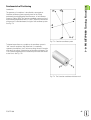
Chamfer
A chamfer is an angled cut which connects two adjacent line blocks
within a program. The POSITIP 880 calculates the location of the
chamfer. The two lines do not have to intersect or touch, however, if
they do touch, the lengths are calculated from their intersection
points. See Fig. I.55 as a graphic example of a chamfer.
A chamfer usually connects the previous block in the program with the
next block to form a continuous path. It is also possible to have the
chamfer connect the previous block to the first block within the
current continuous path. This “closes” the path.
Fig. I.54 Input parameters for a chamfer
Intersecting lines – You can insert a chamfer between two
intersecting lines that are adjacent in the program sequence. See Fig.
I.54.
Length 1
Line 1
Line 1
A chamfer step can be specified by:
8
Length 2
Line 2
Length 1 and length 2, the angle is blank.
Length 1 or length 2 and the angle.
Line 2
8
Angel
Angel
The axis lines must show they are currently at or will come
to a point of connection in order to create a chamfer.
Length 1
Line 1
Operating mode: PROGRAMMING
Line 2
Press the PROGRAMMING FEATURES soft key.
Length 2
Press the MORE soft key twice.
Fig. I.55 Example of a chamfer
Press the CHAMFER soft key.
The “FROM” and “TO” fields are read only. They are
automatically filled when the CHAMFER form is
opened.
To close the path using a chamfer, enter the
chamfer’s data and press the CLOSE CONTOUR soft key.
68
I Operating Instructions
I – 6 Programming POSITIP 880
LENGTH 1
Enter the distance from the point of intersection on
the line in the “FROM” step. Use the numeric keys to
enter the distance.
LENGTH 2
Enter the distance from the point of intersection on
the line in the “TO” step.
ANGLE
Enter the angle measured from the line along the X
axis and sweeps toward the adjacent line. Use the
numeric keys to enter the angle.
CLOSE CONTOUR
Pressing the CLOSE CONTOUR soft key causes the
chamfer to connect the first block in the current path
instead of the next block. The block number shown in
the “TO” field will change.
When the desired data has been entered, press USE.
POSITIP 880
69
I – 6 Programming POSITIP 880
File Operation Soft Keys
Function
Soft key
Load from internal storage or to current
program memory
Save current program in memory to internal
storage
Delete program from internal storage
Clear current program in memory
Select a directory for internal storage
Create a name for a new directory
Delete a directory from internal storage
Allows the operator to transfer a program from
an external device into POSITIP 880's program
memory.
Allows the operator to transfer a program from
POSITIP 880 to an external device (PC or
printer).
Loading, saving, deleting & clearing a program
POSITIP 880 allows you to load programs from internal storage to
current program memory.
To load or delete a program:
Press the FILE OPERATIONS soft key.
Press the LOAD soft key.
Choose the desired program and press LOAD.
Confirm with YES. Follow the same procedure for
deleting a program, except press DELETE soft key.
70
I Operating Instructions
I – 6 Programming POSITIP 880
To save a program:
Press the FILE OPERATIONS soft key.
Press SAVE soft key.
To spell the name of the new program, use the LEFT
and RIGHT soft keys and the Up/Down arrow keys to
move through the selection of alphabetized
characters.
Choose desired characters, by pressing the SELECT
CHARACTER soft key to spell the name of the new
program.
To enter numerals in the name, press the numeric
keypad.
Use CE key to backspace.
When you have completed spelling the new program
name, select the SAVE soft key.
To clear a program:
Press the FILE OPERATIONS soft key.
Press CLEAR soft key. Confirm with Yes.
Directories
POSITIP 880 allows the operator to create directories in which to
maintain and store part programs. Press the MORE soft key to access
these functions.
Function
Soft key
Select a directory
Create a name for a new directory
Delete a directory
POSITIP 880
71
I – 6 Programming POSITIP 880
Selecting a directory
To select a directory:
Press the FILE OPERATIONS soft key.
Press MORE soft key.
Press the SELECT DIRECTORY soft key.
Choose the desired directory and press SELECT.
Creating a directory
To create a directory:
Press the FILE OPERATIONS soft key.
Press MORE soft key.
Press CREATE DIRECTORY soft key.
Spell the name of the new directory, using the LEFT
and RIGHT soft keys and the Up/Down arrow keys to
move through the selection of alphabetized
characters.
To enter numerals to the name use the numeric
keypad
Choose desired characters, by pressing the SELECT
CHARACTER soft key
Use CE key to backspace.
When you have completed spelling the new directory
name, select the CREATE soft key.
72
I Operating Instructions
I – 6 Programming POSITIP 880
Deleting a directory
To delete a directory:
Press the FILE OPERATIONS soft key.
Press MORE soft key.
Press the DELETE DIRECTORY soft key.
Choose the desired directory and press DELETE.
Confirm with Yes.
Importing a Program
The RS-232-C interface on the rear panel allows you to utilize a device
such as a PC for external data storage.
Pin layout, wiring and connections for the data interface
see Chapter II-4 Data Interface.
If the device is not properly connected you will receive an
error message.
Example: Importing a program into POSITIP 880
Operating mode: PROGRAMMING
Press the FILE OPERATIONS soft key.
Press the MORE soft key twice.
IMPORT PROGRAM
Press the IMPORT PROGRAM soft key.
Setup the PC host terminal program to send the
program file as ASCII text data.
If you are importing programs into POSITIP 880 from a PC, the PC
must send the programs.
POSITIP 880 will load the new program into program memory only.
You will have to save it to internal storage if necessary. The external
device (PC) must be connected through the serial port.
POSITIP 880
73
I – 6 Programming POSITIP 880
Exporting a Program
Example: Exporting a program from POSITIP 880
Setup the PC host terminal program to receive the
ASCII text data and to save the data to a file.
Press FILE OPERATIONS
Press MORE (twice)
Press EXPORT PROGRAM
If you are transferring programs from POSITP 880 to a PC, the PC
must be ready to receive the program before pressing EXPORT
PROGRAM.
Block Function Soft Keys
A block is a single step or a series of steps that make up a program.
Operating mode: PROGRAMMING
Press the BLOCK FUNCTIONS soft key.
Function
Soft key
This feature will “explode” a program block
into several more detailed blocks. Applies to
hole patterns and REPEAT, ROTATE and
MIRROR blocks.
Change depth or offset for a range of blocks.
Delete a range of blocks from current program.
Copy a range of blocks within the current
program.
Move a range of blocks within the current
program.
Reverse order of blocks in a path and the
“from” and “to” points in each block.
Adjusts the end point of current block and start
point of the next block to the intersection point
of the two features.
74
I Operating Instructions
I – 6 Programming POSITIP 880
Function
Soft key
Adjusts the start point of current block and end
point of the previous block to the intersection
point of the two features.
Adjusts the end point of the last block in the
path and the start point of the first block in the
path to the intersection point of the two
features
Explode
This feature will “explode” a program block into several more detailed
blocks. You can explode hole functions and CALL LABEL REPEAT,
ROTATE and MIRROR. The step that you exploded will be replaced
with the individual lines and arcs (CALL LABEL REPEAT, ROTATE and
MIRROR) or positions (hole patterns) that made up the original block.
Highlight the block you want to explode.
Press the BLOCK FUNCTIONS soft key.
Press the EXPLODE soft key.
POSITIP 880
75
I – 6 Programming POSITIP 880
Changing program blocks. See Fig. I.56.
Operating mode: PROGRAMMING
From within BLOCK FUNCTIONS, press the CHANGE
BLOCKS soft key.
Select the range of blocks you want to change (FIRST
and LAST). Press ENT after each selection.
Enter the Z axis depth manually using either the
numeric keypad or select the THRU soft key. Press ENT.
Enter the tool offset: LEFT, CENTER or RIGHT. Press
USE. This applies to lines and arcs within the range
only.
Fig. I.56 Changing a program block
Deleting, copying and moving program blocks
You can delete, copy or move a range of blocks.
When a block is deleted, POSITIP 880 automatically renumbers the
remaining blocks. The block after the deleted block then becomes the
current block.
Example: Delete program blocks
Operating mode: PROGRAMMING
From within BLOCK FUNCTIONS, press the DELETE
BLOCKS soft key.
Select the range of blocks you want to delete (FIRST
and LAST). Press ENT after each selection.
Press USE.
76
I Operating Instructions
I – 6 Programming POSITIP 880
Trim blocks
You can trim, or connect, two adjacent line blocks using the trim
feature. The trim feature connects the two blocks by extending each
line to the point where they intersect.
Move the cursor to the line block to be trimmed.
Press the TRIM NEXT soft key. The end point of the
current line and the start point of the next line will be
set to the point where both lines intersect.
Move the cursor to the line block to be trimmed.
Press the TRIM PREVIOUS soft key. The start point
of the current line and the end point of the previous
line will be set to the point where both lines intersect.
Move the cursor to the line block to be trimmed.
Press the TRIM PATH soft key. The end point of the
last line and the start point of the first line in the path
will be set to the point where both lines intersect.
POSITIP 880
77
I – 7 Executing a Program
I – 7 Executing a Program
Preparing to Run a Program
When you are ready to run a program, you must be in the EXECUTE
PROGRAM mode. Press the EXECUTE PROGRAM hard key, then the
FILE OPERATIONS soft key, press the LOAD soft key, scroll to the desired
program, then press the LOAD soft key again. The current program
block is displayed at the top of the screen.
Black to gray feature
This feature is an on-screen visual aid. The axes that need to be moved
into position will be shown in black in the axes bar. When you get into
position they will switch to gray. Note: If your depth axis is set to
THRU, the depth axis will not switch to gray.
Operating mode: PROGRAMMING
You will be given a choice of how you want to run the program: Single
block or automatic.
Single block
When you have moved the axis to the displayed position, call the
next block with the NEXT BLOCK soft key. It is recommended that you
use SINGLE BLOCK when running a program for the first time.
Automatic
Here the display automatically shows the next program block as
soon as you have moved to the displayed position. Press AUTOMATIC
when you are sure the program contains no errors and you want to
run it quickly. When all displayed axes have switched to gray
(indicating that they are in position) the program advances to the
next block or hole.
Single block example
Operating mode: EXECUTE PROGRAM
Fig. I.57 1st EXECUTE PROGRAM screen
Select SINGLE BLOCK. The program block and the
graphic positioning aid will appear (if currently in use).
Position by traversing to display value zero.
Call the next program block by pressing NEXT BLOCK.
Continue positioning and calling blocks with NEXT BLOCK until
machining is complete.
78
I Operating Instructions
I – 7 Executing a Program
Automatic example:
Operating mode: EXECUTE PROGRAM
Select AUTOMATIC.
Position by traversing to display value zero.
The display automatically shows the next program
block as soon as you have moved to the displayed
position. The positioning aid automatically switches
to the coordinate axis of the new block.
Call the next program block by pressing NEXT BLOCK.
Function
Soft key/Key
Start with the block before the current block
(this key is available prior to running a program).
Start with the block after the current block (this
key is available prior to running a program).
Enter into the tool data (this key is available
prior to running a program).
Used in either SINGLE BLOCK or AUTOMATIC
mode. Used only during execution of hole
patterns. Press to advance to the next hole in a
hole pattern.
Used in either SINGLE BLOCK or AUTOMATIC
mode. Used only during execution of hole
patterns. Press to step back to the previous
hole in a hole pattern.
Used in either SINGLE BLOCK or AUTOMATIC
mode. Used only during execution of pocket
patterns. Press to advance to the next step in a
pocket pattern.
Used in SINGLE BLOCK or AUTOMATIC mode
for the operator to advance manually to the
next block within a program.
Press to abort the AUTOMATIC or SINGLE
BLOCK mode and return to the previous
screen.
POSITIP 880
79
I – 7 Executing a Program
Program views
The POSITIP 880 allows the operator to see several different views of
the current operation. After choosing SINGLE BLOCK or AUTOMATIC to
begin an operation, the soft key on the far left will offer several
viewing options starting with VIEW (PGM/DRO). Toggle through to
choose other view options.
Operating mode will automatically switch to: EXECUTE PROGRAM
Function
View
Shows all axis coordinates and each input
parameter in the current operation.
Shows enlarged view of axis display
coordinates.
Shows the graphical layout of the current
machining parameters.
Shows the necessary feedback for precise
positioning or for following a contour along the
machining plane.
80
I Operating Instructions
I – 7 Executing a Program
Contour View
The contour view is an optional display screen available when
executing a program. The view will only appear if turned on. Refer to
section I-8 Job Setup for instructions. See Fig. I.58 & Fig. I.59.
Graphic displays
The contouring view provides the necessary feedback for positioning
precisely or for following a contour along the machine plane.
The screen consists of a main view showing the tool path and hole
locations, a smaller window showing the full part, and another smaller
DRO window showing current position.
Please note that this display only allows the operator to
approximately machine along a complex path. The
approximation of the cut to the actual programmed path is
solely a function of the skill and patience of the operator.
Main view
The main view is used for finer positioning. It’s scaling is such that one
pixel on the display is equal to the finer of the X and Y axis display
resolutions. This allows scale motion of 1 encoder pulse to be visually
discernible.
A tool icon is fixed in the center of the view. The tool path is displayed
relative to the tool. As the table is moved, the tool path moves relative
to the tool only.
The tool icon is not displayed to scale. It represents the center of the
tool only.
The tool path is offset from the programmed contour by the tool radius
and tolerance band. The tool’s path is relative to the tool selected.
Contour is turned on and off in JOB SETUP.
Fig. I.58 Test program in contour view
Contours
For lines and arcs the tool path is shown. The tool path includes any
offset specified in the program.
On either side of the tool path is a tolerance band. The tolerance band
parameter is setup in JOB SETUP. The gap between the tool path and
the tolerance band represents the allowable deviation from the tool
path. The inside tolerance band is shown in red. The outside tolerance
band is shown in green.
Fig. I.59 Test program in contour view
POSITIP 880
81
I – 7 Executing a Program
Positions and hole patterns
For positions and hole patterns, the position or center of the hole is
shown as a cross-hair.
A circle around the position/hole location represents the tolerance
band. When the center of the tool icon is within the circle, the cutting
is within the tolerance band.
Full part window
The full part window provides for very coarse positioning. It shows the
tool relative to the entire part. The scaling is such that the entire part
will fit within the window with a small buffer all around.
The part profile is fixed. The tool icon is shown to scale using the
current tool’s radius. As the table moves, the tool icon moves relative
to the part.
The shaded area represents the stock material. It is shown slightly
larger than the part's extents. As the tool icon moves, the shading
below the tool changes to background gray. This material removal
allows the shading to be used as an indication of the material
remaining.
The material removal mechanism functions only while the contouring
view is shown. If the tool is moved while another view is selected, the
affected material will not be removed in the contour view.
DRO window
The contour view provides the necessary feedback for positioning
precisely or for following a contour along the XY plane.
The DRO window shows the distance-to-go positions for X, Y and Z
axis. The DRO window allows viewing the position without switching
to another view.
82
I Operating Instructions
I – 8 INFO Screen
I – 8 INFO Screen
JOB SETUP Menu
The JOB SETUP menu is accessed by pressing the INFO soft key the
JOB SETUP soft key and then ENT. See Fig. I.60. When in the JOB
SETUP menu, the following soft keys will be available:
INSTALLATION SETUP
Press to begin accessing the INSTALLATION SETUP parameters.
IMPORT/EXPORT Press to begin importing or exporting the
operating parameters.
CANCEL CHANGES Will cancel all changes and exit from JOB
SETUP back to the previous mode.
USE NEW SETTINGS Will save any changes to the configuration
file before exiting.
HELP
Will open on-line help.
General field/form navigation guide
Press Up/Down arrow keys to move between fields.
Use keypad to enter numeric values within each field.
Press ENT to confirm the entry within a field.
Press USE when form is completed and save settings to the form.
Press USE NEW SETTINGS to return to the INFO screen.
Fig. I.60 JOB SETUP screen in milling
To access the JOB SETUP menu:
Press the INFO soft key.
Press the JOB SETUP soft key.
The cursor will default to the first selection on the
menu: TOOL TABLE
POSITIP 880
83
I – 8 INFO Screen
Tool table (Milling only)
The tool table will support up to 99 tools containing information on the
diameter, length and type. The length offset may be entered as a
known value or the POSITIP 880 may determine the offset
automatically. See Fig. I.61.
The following soft keys are available:
Function
Soft key
Press to enter the tool offset length. Only
available in TOOL LENGTH field.
This will open the TOOL TYPES form for
selection. Only available in TYPE field.
This key will sort all entered tools by type (i.e.,
flat end mills with flat end mills, etc.).
Fig. I.61 Tool table in milling
This key will allow the operator to select
between tool axes (X,Y,Z).
84
I Operating Instructions
I – 8 INFO Screen
Tool Table Usage
Example: Entering the tool length and diameter into the tool
table. See Fig. I.62 & Fig. I.63.
Tool diameter 3.00
Tool length: 25.000
Tool unit: mm
Tool type: flat end mill
It is also possible to have POSITIP 880 determine an
offset. See alternative example below.
Press the INFO soft key, then the JOB SETUP soft key.
The cursor will default to the TOOL TABLE field.
Press ENT.
TOOL TABLE
Fig. I.62 Tool length and diameter entry
Cursor to the tool you want to define or enter the tool
number. Press ENT.
TOOL DIAMETER
Enter the tool diameter (3.0) and
press ENT.
Cursor will automatically move to the LENGTH field.
POSITIP 880
85
I – 8 INFO Screen
TOOL LENGTH
If a tool presetter is used to measure the length of a
tool, enter the tool length (25 mm) and press ENT.
It is also possible to have POSITIP 880 determine an
offset. This method involves touching the tip of each
tool to a common reference surface. This allows
POSITIP 880 to determine the difference between
the length of each tool.
Move the tool until its tip is touching the reference
surface.
Press the TEACH OFFSET soft key. POSITIP 880 will
calculate an offset relative to this surface. Press ENT.
Repeat the procedure for each additional tool using
the same reference surface.
Only the tools set using the same reference surface may
be changed without having to set the datum.
Fig. I.63 TOOL TYPE field
If the tool table already contains tools in which the length
has been set, the reference surface should first be
established using one of them. If not, you will not be able
to switch between the new tools and the existing tools
without having to re-establish the datum. Before adding
the new tools, select one of the tools from the tool table.
Touch the tool to the reference surface and set the datum
to 0.
Cursor will automatically move to the UNIT field.
TOOL UNIT
Enter the tool unit (inch/mm) and
press ENT.
Cursor will automatically move to the TYPE field.
86
I Operating Instructions
I – 8 INFO Screen
TOOL TYPE
If you want to set the type, press TOOL TYPES soft
key. Select from list and press ENT.
Press USE soft key twice, then the USE NEW SETTINGS
soft key once.
The tool table may be protected to prevent changes from
being made to the tool information. Refer to II-2
Installation Setup.
Tool axis setting
A tool axis is selected to define the machining plane. Tool radius
compensation is applied to the axes forming the machining plane. Tool
length compensation is applied along the tool axis.
For example, a horizontal boring machine may have machining
features such as hole patterns located in the YZ plane. The boring
operations are performed in the X-axis. For this configuration, the tool
axis would be set to the X-axis.
8
8
8
Press the TOOL AXIS soft key.
Select the axis by pressing one of the soft keys.
Press USE, then USE NEW SETTINGS soft key.
Tool selection and tool axis selection take effect
immediately. Pressing the CANCEL CHANGES soft key does
not restore the previous settings.
POSITIP 880
87
I – 8 INFO Screen
Datum table (milling only)
The datum table shows the absolute locations of the datums relative
to the reference mark. Normally the datums are set using the datum
and probe functions in actual value mode. It is also possible to set the
datum values directly if necessary. See Fig. I.64.
8
8
8
Press the arrow keys to cursor to the datum you need and press ENT.
The datum description form will appear.
Use numeric keys to enter the desired values and press ENT for each
axis. The values are measured from the reference marks.
When you have finished entering values, press the USE soft key.
Resetting the datum table:
8
Press the RESET ALL DATUMS soft key to reset all axis values in the
datum table.
Datum number 0 may be protected to prevent it from
being changed. Refer to II-2 Installation Setup.
Fig. I.64 Datum table in milling
Display configuration
The DISPLAY CONFIGURATION form is where the operator
determines which axes are displayed and in what order. The DRO
display may have 1 or 2 independent configurations.
8
8
8
8
8
Press the NEXT AXIS soft key to toggle through the available axes.
Press the CE key to turn off the axis display.
The form is closed by pressing the CANCEL or USE soft keys.
The factory default configuration for DRO 1 is 1st = X, 2nd = Y, and
3rd = Z. The 4th, 5th, and 6th displays are OFF. The default for
DRO2 is all displays OFF.
When more than 1 configuration is available, the DRO VIEW soft key
is used to toggle between DRO1 and DRO2. The current setting is
shown on the soft key. On power up, the DRO display defaults to
DRO1.
Scale factor
The scale factor may be used to scale the part up or down from the
programmed size. All displayed values are multiplied by the scale
factor. Tool radius offsetting is not affected. A scale factor of 1.0 is
used to create a part with the exact size as dimensioned on the print.
See Fig. I.65.
8
8
8
The numeric keys are used to enter a number greater than zero. The
range is 0.1000 to 10.000.
The scale factor settings will be retained on a power cycle. First-time
power-up default setting is OFF with a value of 1.0000.
When the scale factor is a value other than 1, the scaling symbol
is shown on the axis display.
Fig. I.65 Scale factor
88
I Operating Instructions
I – 8 INFO Screen
Diameter axes
Select DIAMETER AXES to set the axis values to either diameter or
radius values depending on the requirements of the drawing. .
8
8
8
Cursor to DIAMETER AXES and press ENT.
The cursor will be in the X axis field. (The field will default to
RADIUS). Depending on the parameter you need for that axis either
press the DIAMETER soft key or press ENT to leave as RADIUS and
advance to the next axis field.
Press USE, then USE NEW SETTINGS.
Radius/Diameter Display
POSITIP 880 can display either the radius or the diameter for you.
When the diameter is being displayed, the diameter symbol (Ø) is
shown next to the position value.
Edge finder (milling only)
The diameter and length offset of the edge finder are set in this form.
Both values are in the units indicated in the form.
The numeric keys are used to enter values of diameter and length. The
diameter must be greater than zero. The length is a sign value
(negative or positive).
Soft keys are used to select the units for the edge finder dimensions.
The entered diameter and length values are not converted when the
units are toggled.
The edge finder values will be retained on a power cycle.
Measured value output
With the measured value output feature, the current axis display
positions and probe measurement values can be sent over the serial
and /or parallel ports. Output of the current display positions is
activated via an external hardware signal (requires optional Auxiliary
Machine Interface) or via a command (Ctrl B) sent to POSITIP 880 over
the serial port.
The Measured Value Output form is used to set data output during
probing operations to On or Off. It is also used to set the display freeze
option.
Data Output Probing - This may be set to either On or Off. When On,
the measurement data is output when the probe operation is
completed.
Display Freeze - Set to either:
Off - The display is not stopped during measured value output.
Concurrent - The display is stopped during measured value output
and remains stopped while the switching input is active.
Freeze - The display is stopped, but is updated by every measured
value output.
Refer to chapter II-5 Measured Value Output for information on the
format of the output data.
POSITIP 880
89
I – 8 INFO Screen
Graphic positioning aid
The GRAPHIC POSITIONING AID form is used to configure the bar
graph that is shown below the axes’ DRO display in DISTANCE-TOGO mode. Each axis has its own range. See Fig. I.66.
8
8
Press the ON soft key to enable or simply begin entering values using
the numeric keys. Enter default value of 5 mm.
Only axes that have been setup in the AXIS CONFIGURATION will
appear in the form. Graphic positioning aid will be retained on a
power cycle.
Stopwatch
The stopwatch shows the hours (h), minutes (m), seconds (s). It
operates like a stop watch showing elapsed time.
The watch starts timing from 0:00:00 when the START soft key is
pressed and stops when STOP is pressed.
It will be reset to 0:00:00 when RESET is pressed. Resetting will stop
the watch if it is running.
Fig. I.66 Graphic positioning aid
The elapsed time field shows the total accumulated time from each
interval.
All stop watch functions are applied immediately. When running, both
the status bar and stop watch and the elapsed time field are updated
in real-time.
90
I Operating Instructions
I – 8 INFO Screen
Units
The UNITS form is used to specify the preferred display units and
format. The system powers up with these settings in effect.
Inch/MM - Measurement values are displayed and entered in the
units selected in the DIMENSIONS field. Choose between INCH or
MM soft keys.
Decimal Degrees, Radians or Degrees/Minutes/Seconds (DMS) The ANGLE FORMAT field affects how angles are displayed and
entered in forms. Choose between these three soft keys DECIMAL
DEGREES, RADIANS or DMS.
CW/CCW - Direction fields in canned cycle forms default to the
direction clockwise or counter-clockwise selected in the
DIRECTION field.
Contour
The CONTOUR form is used to enable or disable the feature and to set
the tolerance bands.
8
8
8
8
Press the ON soft key to enable the feature. The contour view will
be available when executing a program.
Press the OFF soft key to disable the feature.
Enter a value for the inside tolerance. The inside tolerance is shown
in red on the screen.
Enter a value for the outside tolerance. The outside tolerance is
shown in green on the screen.
Console adjustment
The brightness can be adjusted for both the main console and the
remote console. The form is also used to set the display saver’s idle
time-out.
The MAIN BRIGHTNESS field applies to the main console. The
REMOTE SETTING applies to the remote console.
The display saver setting is the amount of time the system is idle
before the display is turned off. The idle time may be set from 30 to
120 minutes. The display saver can be disabled during the current
power cycle.
POSITIP 880
91
I – 8 INFO Screen
Installation Menu
Refer to the Technical Information section for Installation Setup
chapter.
Calculator
POSITIP 880’s calculator is capable of handling everything from simple
arithmetic to complex trigonometry and RPM calculations. The
numeric keypad acts as a standard calculator with keys for numbers 0
through 9, a decimal point, a positive/negative sign (+/-) and CE to clear
an entry.
The calculator is accessible from the INFO soft key. Press the
CALCULATOR soft key to access the STANDARD/TRIG and RPM softkeys.
Calculations can be entered directly into a highlighted field. See Fig.
I.67 & Fig. I.68.
Fig. I.67 Calculator soft keys
Taper calculator functions are available for lathe operations only.
The calculator functions are:
Standard/Trigonometry
RPM
Reference tables
Fig. I.68 1st row calculator soft keys
92
I Operating Instructions
I – 8 INFO Screen
Math functions (+, –, x, /)
Math functions may be performed separately in the stand-alone
calculator or directly in the field you’re working in. For example, let’s
say we need to enter the radius of a circle pocket, but your print only
shows the diameter, 6.25. Here’s an easy way to figure out the radius:
8
8
8
8
8
8
8
8
8
Highlight the RADIUS field for the circle pattern.
Using the keypad, enter the value for the diameter, 6.25.
Press INFO.
Press CALCULATOR.
Press the TRIG soft key.
Press the / soft key.
Press the 2 key.
Press the ENT key. The answer, 3.125, will appear in the VALUE
field.
Press USE. Value will be shown in the RADIUS field.
Fig. I.69 2nd row of calculator soft keys
When you need to enter more than one calculation into a
numeric field, the calculator will perform multiplication and
division before it performs addition and subtraction. If you
were to enter 3 + 1 / 8, POSITIP 880 will divide one by
eight, then add three for an answer of 3.125.
Trig functions
As we showed above, when you’re entering data for a milling or
positioning function, your print may not provide you with all of the
information you need. If an unknown value can be expressed as a
trigonometry function, square root or the square of a number,
POSITIP 880 can calculate the dimension for you in the trigonometry
calculator. See Fig. I.69 & Fig. I.70.
Using the trig calculator:
8
8
8
While in a numeric field (such as the “TO” field for a line), press the
INFO soft key, the CALCULATOR soft key, and then press the
STANDARD/TRIG soft key. Press the MORE soft key and the soft key
row in the picture to the right will appear:
Press the MORE soft key to toggle between the three soft key rows.
Enter a number and then press the soft key for the appropriate
trigonometry math function.
For example, to enter a radius that has a value equal to the square root
of 2, follow this procedure:
8
8
8
8
8
8
Fig. I.70 Trig function soft keys
Highlight the RADIUS field.
Press the 2 key.
Press INFO.
Press CALCULATOR.
Press the TRIG soft key.
Press the SQR ROOT soft key. A value of 1.4142 will appear.
POSITIP 880
93
I – 8 INFO Screen
Whenever you're calculating the SIN, COS or TAN of an angle, enter
the angle first and then press the appropriate soft key. If you were to
enter a value of 30 into a numeric field, then press the SIN soft key, a
value of 0.5 (the SIN of 30 degrees) would appear.
Continuing, let’s assume that we are trying to set up a 10 cm SIN bar
at a 30° angle and need to know how tall the block underneath it
should be. If we multiply 0.5000 by 10, we know that we need to use
a 5 cm block.
Angle values use the current angle format selection of
decimal degrees, DMS, or radians.
RPM calculator
The RPM calculator is used to set the RPM (or surface cutting speed)
based on a specified tool diameter. See Fig. I.71.
8
8
8
Press the RPM soft key to open the RPM CALCULATOR form.
The RPM calculator requires a tool diameter. Use the numeric hard
keys to enter a diameter value. The diameter value will default to the
current tool diameter if no new value is entered. If there is no
current tool, the default value is 0.
If a surface speed value is required, enter the value using the
numeric hard keys. When a surface speed value is entered, the
associated RPM value will be calculated.
Surface speed table
8
8
8
When in the SURFACE SPEED field, a soft key is available for
opening on-line help. The table may be consulted for a
recommended range of surface speeds for the material being
machined.
Press either the FEET/MIN or METERS/MIN soft key depending on the
current units.
The RPM CALCULATOR form is closed by pressing the USE soft key.
There is no return value.
Fig. I.71 RPM CALCULATOR form
Reference tables
8
Press the REFERENCE TABLES soft key to open on-line help reference
tables.
94
I Operating Instructions
I – 8 INFO Screen
Language
The POSITIP 880 supports multiple languages. To change the
language selection:
8
8
8
8
Press INFO.
Press the LANGUAGE soft key.
Press the LANGUAGE soft key until the desired language selection
appears on the soft key.
Press USE and confirm your selection. The system will restart.
Changing from one language to another will restart the
system. This is equivalent to cycling power. It will be
necessary to cross over the reference marks to reestablish the current datum settings and reload the current
program.
Inch/MM
Positions can be displayed and entered in millimeters or inches. If you
choose inches, INCH will be displayed on the status bar at the top of
the screen.
To change the unit of measure:
8
8
8
Press INFO.
Press the INCH/MM soft key.
The unit of measure can also be set in JOB SETUP. Refer to Job
Setup, chapter I-8.
POSITIP 880
95
I – 9 POSITIP 880 Turning Functions
I – 9 POSITIP 880 Turning Functions
To enter POSITIP 880 for turning functions:
Power Up
Switch on the power (located on the back). It will take
approximately 25 - 30 seconds for system to start
after power up. The initial screen will appear (This
screen will only appear the first time you power
up). Select the language by pressing the LANGUAGE
soft key. See Fig. I.72.
Select the TURN soft key to continue with turning
functions. You can change the application later in
INSTALLATION SETUP under COUNTER SETTINGS.
If you are a novice user to the POSITIP 880 you
should review the first 4 sections of this manual for
information common to both milling and turning
applications.
Fig. I.72 Initial screen
Your POSITIP 880 is now ready for operation and is in the operating
mode ACTUAL VALUE.
96
I Operating Instructions
I – 9 POSITIP 880 Turning Functions
Fundamentals of Positioning
Introduction
The geometry of a workpiece is described by a rectangular or
Cartesian coordinate system (named in honor of the French
mathematician and philosopher René Descartes, in Latin Renatus
Cartesius, 1596 to 1650). The Cartesian coordinate system consists of
three mutually perpendicular axes X, Y and Z. The point of intersection
of these axes is called the datum (or origin) of the coordinate system.
See Fig. I.73.
Fig. I.73 Cartesian coordinate system
To determine positions on a workpiece, the coordinate system is
“laid” onto the workpiece. With lathe work (i.e. rotationally
symmetrical workpieces), the Z axis moves along the axis of rotation
while the X axis moves in the direction of the radius or diameter. The
Y axis can be disregarded since it would always have the same values
as the X axis. See Fig. I.74.
Fig. I.74 The Cartesian coordinate with lathe work
POSITIP 880
97
I – 9 POSITIP 880 Turning Functions
Job Setup for Turning Applications
Two of the features in this JOB SETUP menu are unique to turning
applications (DIAMETER AXES, OVERSIZE). See chapter I-8 Job Setup
Menu for descriptions of the other general Job Setup features. See
Fig. I.75.
The JOB SETUP menu is accessed by pressing the INFO soft key, then
the JOB SETUP soft key. When in the JOB SETUP menu, the following
soft keys will be available:
INSTALLATION SETUP
Press to begin accessing the INSTALLATION SETUP parameters.
IMPORT/EXPORT Press to begin importing or exporting the
configuration file.
CANCEL CHANGES Will cancel all changes and exit from JOB
SETUP back to the previous mode.
USE NEW SETTINGS Will save any changes to the configuration
file before exiting.
HELP
Will open on-line help.
Fig. I.75 JOB SETUP screen in turning
To access the JOB SETUP menu:
Press the INFO soft key.
Press the JOB SETUP soft key.
The cursor will default to the first selection on the
menu: TOOL TABLE
Tool table (turning only)
The tool table will support up to 99 tools containing information on
each axis. If you have measured your tools using a tool presetter, the
offsets may be entered directly. See Fig. I.76.
Fig. I.76 Tool table in turning
98
I Operating Instructions
I – 9 POSITIP 880 Turning Functions
Tool Table Usage
Example: Entering offsets into the tool table
Press the INFO soft key, then the JOB SETUP soft key.
The cursor will default to the TOOL TABLE field.
Press ENT.
TOOL TABLE
Cursor to the tool you want to define or enter the tool
number. Press ENT.
POSITIP 880
99
I – 9 POSITIP 880 Turning Functions
TOOL DESCRIPTION
If a tool presetter is used to measure the length of a
tool, enter the tool offset (25 mm) and press ENT.
Press USE soft key twice, then the USE NEW SETTINGS
soft key once.
The tool table may be protected to prevent changes from
being made to the tool information. Refer to II-2
Installation Setup.
Diameter axes
Select DIAMETER AXES to set the axis values to either diameter or
radius values depending on the requirements of the drawing. See Fig.
I.77.
8
8
8
Cursor to DIAMETER AXES and press ENT.
The cursor will be in the X axis field. (The field will default to
RADIUS). Depending on the parameter you need for that axis either
press the DIAMETER soft key or press ENT to leave as RADIUS and
advance to the next Z AXIS field.
Press USE, then USE NEW SETTINGS.
Fig. I.77 DIAMETER AXES form
100
I Operating Instructions
I – 9 POSITIP 880 Turning Functions
Radius/Diameter Display
Drawings for lathe parts usually give diameter values. POSITIP 880
can display either the radius or the diameter for you. When the
diameter is being displayed, the diameter symbol (Ø) is shown next to
the position value. See Fig. I.78.
Example: Radius display, position 1 X = 20 mm
Diameter display, position 1 X = 40Ø mm
Fig. I.78 Workpiece for radius/diameter display
Oversizes
Oversizes are entered in the JOB SETUP menu. Oversizes are
automatically taken into account in the DISTANCE-TO-GO mode. When
the displayed distance-to-go is 0, only the oversize amount remains.
When you have set the OVERSIZE field to ON, a symbol for oversize
appears on the right side of the axis bar. See Fig. I.79.
Oversize symbol:
Entry sizes for oversize and undersize
Oversize: Positive entry value (up to 999.999 mm).
Undersize: Negative entry value (down to -999.99mm).
Entering oversizes
8
8
8
8
Cursor to OVERSIZE and press ENT.
To enter value either press ON soft key or simply begin entering the
desired value for that axis. Press ENT to advance to the next axis
field.
To work without oversizes, either press the OFF soft key for each
axis field or enter 0 for each field.
Press USE, then USE NEW SETTINGS.
POSITIP 880
Fig. I.79 OVERSIZE form
101
I – 9 POSITIP 880 Turning Functions
Tool Offsetting
The POSITIP 880 can store the dimensional offsets for up to 99 tools.
When you change a workpiece and establish a new datum, all tools are
automatically referenced from the new datum.
Before you can use a tool, you must enter its offset (the cutting edge
position). Tool offsets can be set using the TOOL/SET or NOTE/SET
features or they can be determined using a tool presetter. Refer to the
section on Tool Table for more information on entering tool offsets.
The TOOL/SET and NOTE/SET soft keys are available when in the
ACTUAL VALUE operating mode. The following outlines the
procedures for setting tool offsets using TOOL/SET and NOTE/SET.
Setting tool offsets using TOOL/SET
The TOOL/SET operation can be used to set a tool’s offset using a tool
when the diameter of the workpiece is known.
Example: Entering tool data when the workpiece diameter is
known
Touch the known diameter in the X axis.
Select the axis (X) key or press the TOOL SET soft key.
Enter the position of the tool tip, for example,
X=10mm. Press ENT.
Touch the workpiece face with the tool.
Cursor to the Z axis.
Set the position display for the tool tip to zero, Z=0.
Press ENT, then press USE.
POSITIP 880 stores the tool data under the tool number in the tool
table. Set the tool data for all other tools as described here.
102
I Operating Instructions
I – 9 POSITIP 880 Turning Functions
NOTE/SET Function
The NOTE/SET function can be used to set a tool’s offset when a tool
is under load and the diameter of the workpiece is not known. See Fig.
I.80.
The NOTE/SET function is useful when determining tool data by
touching the workpiece. To avoid losing the position value when the
tool is retracted to measure the workpiece, this value can be stored by
pressing NOTE.
To use the NOTE/SET function:
Press the NOTE/SET soft key.
Select an axis key, such as X.
Fig. I.80 NOTE/SET Form
Turn the first diameter in the X axis.
Press the NOTE soft key.
Retract from the current position.
Measure the workpiece distance.
Enter the measured distance or radius, for example,
15 mm and press ENT.
Press USE.
POSITIP 880
103
I – 9 POSITIP 880 Turning Functions
Datum Setting
Example: Setting the workpiece datum (zero point)
The datum is set to zero for the display of the Z axis. All tool data
entered are automatically referenced to this datum.
Operating mode: ACTUAL VALUE
Machine the workpiece face. Leave the cutting edge
of the tool at the face.
Press the DATUM soft key.
Cursor to the Z axis.
Enter a value, for example 0. Press ENT, then press
USE.
Taper Calculator
Use the taper calculator to calculate the taper angle. See Fig. I.81.
Entry values:
For the taper ratio, calculation requires:
Radius of the taper
Length of the taper
From both diameters and the length, calculations of the:
Starting diameter
End diameter
Length of the taper
Fig. I.81 TAPER CALCULATOR form
104
I Operating Instructions
I – 9 POSITIP 880 Turning Functions
Press the INFO soft key.
Press the CALCULATOR soft key.
You will notice the soft key selection has changed and
now includes the TAPER CALCULATOR function.
Press the TAPER CALCULATOR soft key.
D1/D2 LENGTH
The soft key in this view toggles between D1/D2/
LENGTH and TAPER RADIUS methods. To calculate
the angle using two diameter lengths, press the D1/
D2 LENGTH soft key.
Using the numeric keys, enter data into DIAMETER 1
and DIAMETER 2 fields. Press ENT after each
selection.
Enter data into the LENGTH field, and the angle,
based on the calculations entered, will appear in the
ANGLE field.
TAPER RATIO
To calculate angles using the ratio of the diameter to
the length, press the TAPER RATIO soft key.
Using the numeric keys, enter data into the RADIUS
and LENGTH fields. Press ENT after each selection.
The calculated ratio and the angle will appear in their
respective fields.
POSITIP 880
105
I – 9 POSITIP 880 Turning Functions
Programming Turning Functions for POSITIP 880
Program capabilities
Operating mode: PROGRAMMING
This section describes the programming capabilities of the
POSITIP 880. The operator can load, save or delete a program from
internal storage in FILE OPERATIONS. The CLEAR function clears the
current program in memory.
Function
Soft key
Allows access to all programming features.
Allows the operator to load, save, delete or
clear a program.
Allows the operator access to all block
functions.
Fig. I.82 Program editing screen
Programming Features Soft Keys
The PROGRAMMING mode has a PROGRAMMING FEATURES soft key
which shows all the blocks that can go into a program. Below is a list
of PROGRAMMING FEATURES soft keys.
Operating mode: PROGRAMMING
Function
Soft key
Opens the TOOL CALL block which is used to
select a specific tool number from the tool table
at run-time.
PRESET is used to locate a target position on
an axis. The PRESET form allows for entering
one or more axis presets. However, multiple
axis presets are entered into the program as
separate preset blocks.
Press to open the MULTIPASS function to turn
a shoulder in any number of passes.
Opens the LABEL NUMBER form to mark the
beginning and the end of a subprogram
LABEL CALL (REPEAT) is used to call a
subprogram 1 or more times. It allows the
subprogram to be offset a specified amount on
each iteration.
LABEL CALL (MIRROR) allows blocks within a
subprogram to be inverted over an axis to
represent a mirror image of that subprogram.
106
I Operating Instructions
I – 9 POSITIP 880 Turning Functions
Function
Soft key
LINE soft key opens the program form for
machining a line.
ARC soft key opens the program form for
machining an arc.
BLEND soft key opens the program form and
NORMAL ARC, INVERTED ARC and CLOSED
CONTOUR soft keys for performing a blend.
CHAMFER soft key opens the program form
and the CLOSED CONTOUR soft key to create
a chamfer.
MORE soft key allows the operator to toggle
through the different soft keys rows.
Multipass
The multipass cycle enables you to turn a shoulder in any number of
passes. See Fig. I.83.
Three blocks are needed to enter into a program:
Cycle block
X coordinate
Z coordinate
The multipass cycle contains all information required for the operation.
Do not delete any blocks from the cycle.
When the program is operating, POSITIP 880 will display the distanceto-go to the two nominal positions immediately following the cycle
block. See Fig. I.84.
Example: Turning a shoulder in any number of passes
Workpiece diameter after machining:
X = 10 mm
End of shoulder:
Z = –30 mm
POSITIP 880
Fig. I.83 Example of MULTIPASS
107
I – 9 POSITIP 880 Turning Functions
Operating mode: PROGRAMMING
Press the PROGRAMMING FEATURES soft key.
Press the MULTIPASS soft key. The program block
MULTIPASS appears on the screen.
X AXIS
Enter the nominal position the X axis.
X = 10
Press ENT or cursor to the Z axis.
Z AXIS
Fig. I.84 Multipass cycle block
Enter the nominal position on the Z axis.
Z= -30
Press ENT.
Press USE.
File Operation Soft Keys
Function
Soft key
Load from internal storage or to current
program memory
Save current program in memory to internal
storage
Delete program from internal storage
Clear current program in memory
Select a directory for internal storage
Create a name for a new directory
Delete a directory from internal storage
108
I Operating Instructions
I – 9 POSITIP 880 Turning Functions
Function
Soft key
Allows the operator to transfer a program from
an external device into POSITIP 880's program
memory.
Allows the operator to transfer a program from
POSITIP 880 to an external device (PC or
printer).
Refer to File Operations in chapter I-6, „Programming POSITIP 880”.
Block Function Soft Keys
A block is a single step or a series of steps that make up a program.
Block function soft keys
Operating mode: PROGRAMMING
Press the BLOCK FUNCTIONS soft key.
Function
Soft key
Change features in a range of blocks
Delete a range of blocks from current program
Copy a range of blocks within the current
program
Move a range of blocks within the current
program
Adjusts the end point of current block and start
point of the next block to the intersection point
of the two features
Adjusts the start point of current block and end
point of the previous block to the intersection
point of the two features
Adjusts the end point of current block and start
point of the first block in the path to the
intersection point of the two features
Refer to Block Functions in chapter I-6, „Programming POSITIP 880”.
POSITIP 880
109
I – 9 POSITIP 880 Turning Functions
CHANGING PROGRAM BLOCKS. (SEE FIG. I.85)
OPERATING MODE: PROGRAMMING
From within BLOCK FUNCTIONS, press the CHANGE
BLOCKS soft key.
Select the range of blocks you want to change (FIRST
and LAST). Press ENT after each selection.
Enter the tool offset, either OUTSIDE or INSIDE. Press
USE.
Fig. I.85 Changing a block form
110
I Operating Instructions
Technical Information
POSITIP 880
111
II – 1 Installation and Electrical Connection
II – 1 Installation and Electrical
Connection
Items Supplied
POSITIP 880 Display Unit
Tilt/Swivel Mount
Power connector
User's Manual
Mounting Location
Locate the unit in a well ventilated area such that it may be easily
accessed during normal operation.
Installation
M4 screws are used to secure POSITIP 880 from below. For the hole
locations: see chapter II-8 Dimensions.
Electrical connection
There are no serviceable items within this unit. Therefore,
the POSITIP 880 should not be opened.
The power cord is the primary means of disconnect. The
length of the power cord is not to exceed 3 meters.
Connect a protective ground to the protective conductor
terminal on the rear of the unit.
This connection must never be interrupted.
Do not engage or disengage any connections while the
unit is under power. Damage to internal components may
result.
Use only original replacement fuses.
The equipment shall be connected for its intended
purpose, or not connected for any use whatsoever.
112
II Technical Information
II – 1 Installation and Electrical Connection
Electrical requirements
Voltage
100 - 240 Vac
Power
35 VA max.
Frequency
50/60 Hz (+/- 3Hz)
Fuse 800 mA/250 Vac, 5 mm x 20 mm, Slo-Blo (line and neutral fused)
Environmental
Protection (EN 60529)
IP 40 back panel
IP 54 front panel
Operating temperature
0° to 45°C (32° to 113°F)
Storage temperature
-20° to 70°C (-22° to 158°F)
Mechanical weight
3.2 kg (7.2 lb.)
Wiring the power connector (See Fig. II.1)
Hot leads: L and N
Ground:
Fig. II.1 Wiring the power connector
Minimum diameter of power connection cable: 0.75 mm2.
Protective earthing
It is necessary to connect the protective conductor
terminal on the rear panel to the star point of machine
ground. Minimum cross-section of the connecting wire:
6 mm2, see Fig. II.2.
Preventative maintenance
No special preventative maintenance is necessary. For cleaning, wipe
lightly with a dry lint-free cloth.
Fig. II.2 The protective conductor terminal on the
rear panel.
POSITIP 880
113
II – 1 Installation and Electrical Connection
Connecting the Encoders
POSITIP 880 can be used with HEIDENHAIN linear and rotary
encoders that provide sinusoidal output (11µApp or 1Vpp) or EnDat
(Encoder Data). The encoder inputs on the rear panel are designated
X1, X2, X3, X4, X5 and X6. See Fig. II.3 & Fig. II.4.
The connecting cable must not exceed 30 m (100 ft.) in length.
Do not engage or disengage any connections while the
unit is under power.
Pin layout for encoder inputs
Pin layout for POSITIP 880:
D-sub connection 15-pin
D-sub
connector
15-pin
Inputsignal
11 µAPP
Inputsignal
1 VPP
Inputsignal
EnDat
1
5 V UP
5 V UP
5 V UP
2
0 V UN
0 V UN
0 V UN
3
I1 +
A+
A+
4
I1 –
A–
A–
5
DATA
6
I2 +
B+
B+
7
I2 –
B–
B–
8
DATA
9
10
5 V Sensor
I0 +
11
I0 –
13
Internal Shield
5 V Sensor
R+
0 V Sensor
12
0 V Sensor
R–
Internal Shield
14
CLOCK
15
CLOCK
Case
114
Fig. II.3 15 pin header X1 - X6 plug pinout for encoder
signal input.
External Shield
II Technical Information
II – 1 Installation and Electrical Connection
The operator can setup any encoder input to go to any axis.
Default configuration:
Encoder input
Mill
Turn
X1
X
X
X2
Y
Z
X3
Z
Xo
X4
W
Zo
X5
U
A
X6
V
Ao
Fig. II.4 Encoder inputs on rear panel.
Connecting an Edge Finder
Connect the HEIDENHAIN Edge Finder to the D-sub input X10 on the
rear panel.
Adapt POSITIP 880 for use with the Edge Finder through the following
operating parameters:
Stylus length
Stylus diameter
Description of operating parameters see Job Setup chapter.
The operator must enter new edge finder settings.
Pin layout for Edge Finder input (see Fig. II.5 for pinout)
Pin
Assignment
Type
1
Internal shield
2
Stand-by
KT 130
6
UP +5 V
KT 130
8
UP 0V
KT 130
13
Switch signal
KT 130
Housing
External shield
All other pins: not assigned
Fig. II.5 15 pin receptacle connector for Edge Finder
POSITIP 880
115
II – 2 Installation Setup
II – 2 Installation Setup
Initial switch-on
When you switch on power to your POSITIP 880 for the first time, the
screen shown in Fig. II.6 appears. You can now select the appropriate
language and the type of application (milling or turning).
Press LANGUAGE to scroll through the user interface languages.
For milling:
8
Press the MILL soft key.
For turning:
8
Press the TURN soft key.
POSITIP 880 automatically provides the functions appropriate to the
selected application.
You can change the application later in INSTALLATION SETUP under
COUNTER SETTINGS.
Fig. II.6 POSITIP 880 screen after initial switch-on
This section contains installation setup parameters. Installation setup
is accessed by pressing the INFO soft key, which brings up
INSTALLATION SETUP soft key. See Fig. II.7: Installation setup screen
Enter the passcode
Press the INSTALLATION SETUP soft key to access the form that
requires a passcode to be entered. The CANCEL and USE soft keys are
also available.
Enter the correct passcode (95148) and press the USE soft key or ENT
hard key. (Once you enter the passcode, it will not have to be entered
again until you cycle power.) This will open a form containing a list of
the INSTALLATION SETUP parameters and the following soft keys:
Function
Press to begin accessing the JOB SETUP
parameter.
Soft key
Fig. II.7 Installation setup screen
Import or Export configuration file over the
serial port.
This will cancel all changes and exit from
INSTALLATION SETUP back to previous mode.
This will update with new settings and save any
changes to the configuration file before it exits.
This will open on-screen help.
116
II Technical Information
II – 2 Installation Setup
General field/form navigation guide
Press Up/Down arrow keys to move between fields.
Use keypad to enter numeric values within each field.
Press ENT to confirm the entry within a field.
Press USE when form is completed and save settings to the form.
Press USE NEW SETTINGS to return to the INFO screen.
Axes Configuration
The configuration parameter allows encoder inputs (X1-X6) to be
assigned to displayable axes. The axis may consist of a single encoder
input or may be a combination of two encoders (2nd encoder position
added or subtracted from the 1st). See Fig. II.8 & Fig. II.9.
This is also where the labels for the axes may be changed (A-Z).
To set up the configuration of each axes:
8
8
8
8
8
8
8
8
8
8
Cursor to AXES CONFIGURATION in the INSTALLATION SETUP
menu and press ENT.
The AXES CONFIGURATION form is displayed.
Use the numeric keys 1-6 to select the corresponding encoder input
for the axis.
Press the CE key to remove the encoder input and OFF will be
displayed. Which ever encoders are not being used should be
switched to the OFF position at this point.
Two encoder inputs can be coupled to an axis by using the numeric
keys and the “+” and “-” soft keys.
Press the SELECT LABEL soft key to bring up the SELECT LABEL
character chooser form and the LEFT, RIGHT, SELECT CHARACTER,
CANCEL and USE soft keys are available.
Use the LEFT and RIGHT soft keys and the Up and Down arrow keys
to highlight the desired character.
Press the SELECT CHARACTER soft key or ENT hard key to select the
character as the axis label and remove the SELECT LABEL form. The
soft keys will return to the previous soft key menu.
When you have finished entering values, press the USE soft key or
the ENT hard key to save the changes for that parameter and return
to the INSTALLATION SETUP menu.
Graph axes functions are for turning functions only. The default
setting for graph axes is to display the Z axis coordinates along the
horizontal axis of the part graphic and the X axis coordinates along
the vertical axis. If your configuration differs from this, press the
HORIZONTAL or VERTICAL soft keys to select the appropriate axes.
POSITIP 880
Fig. II.8 AXES CONFIGURATION form (turning)
Fig. II.9 AXES CONFIGURATION form (milling)
117
II – 2 Installation Setup
Encoder Setup
The ENCODER SETUP is used to set the encoder resolution and type
(linear, angular), count direction, reference mark type. See Fig. II.10.
8
8
8
8
8
8
8
8
8
8
8
8
Cursor to the ENCODER SETUP to open a list of 6 possible encoders.
Cursor to the encoder you want to change and press ENT.
The ENCODER SIGNAL field will already be determined.
Cursor will be in the SIGNAL PERIOD field, select the encoder type
by pressing the ENCODER TYPE soft key. The default linear encoder
signal period is 20 µm.
For linear encoders, use COARSER or FINER soft keys to select the
encoder’s signal period in µm (2, 4, 10, 20, 40, 100, 200, 10 240, 12
800) or type in the exact signal period desired. For rotary encoders,
enter the encoder’s line count. The default encoder type is linear.
Refer to II-3 for values.
In the RESOLUTION field, select the COARSER or FINER resolution
value. Default linear resolution is 1 µm.
In the REFERENCE MARK field, select whether the encoder has no
reference mark with the NONE soft key, a single reference mark with
the SINGLE soft key or a distance-coded reference mark with the
CODED soft key.
For coded reference marks, press the CODED soft key to select 500,
1000, 2000 or 5000. The default value is CODED with a spacing of
1000. Refer to II-3 for values.
In the DIRECTION field, select the count direction by pressing the
POSITIVE or NEGATIVE soft key. If the encoder’s count direction
matches the user’s count direction, select positive. If the directions
do not match, select negative. The default count direction is
POSITIVE.
In the ERROR MONITOR field, select whether signal and slew
errors should be monitored by selecting ON or OFF. The default is ON.
When an error message occurs, press the CE (Clear Entry) key to
remove.
For rotary encoders, an ANGLE DISPLAY field will be available.
Select how the angle will be displayed by choosing between three
separate soft keys to toggle through the available options. Choose
between 0° TO 360°, -180° TO +180°, or -INF° TO INF°. The default
is 0° TO 360°.
When complete, select USE, then cursor to the next encoder input
field if necessary.
118
Fig. II.10 ENCODER SETUP form
II Technical Information
II – 2 Installation Setup
Error Compensation
The distance a cutting tool travels, measured by an encoder, can in
certain cases, differ from the actual tool travel. This error can occur
due to ball screw pitch error or deflection and tilting of axes. This error
can either be linear or non-linear. You can determine these errors with
a reference measurement system, e.g. the VM 101 from
HEIDENHAIN or with gauge blocks. From an analysis of the error it can
be determined which form of compensation is required, linear or nonlinear error.
The POSITIP 880 provides the opportunity to compensate for these
errors and each axis can be programmed separately with the
appropriate compensation.
Error compensation is only available when using linear
encoders.
POSITIP 880
119
II – 2 Installation Setup
Linear Error Compensation
Linear error compensation can be applied, if the results of the
comparison with a reference standard show a linear deviation over the
whole measuring length. In this case the error can be compensated by
the calculation of a single correction factor. See Fig. II.11 & Fig. II.12
To calculate the linear error compensation use this
formula:
Correction factor LEC =
with
( S M– M ) x 10
6
ppm
S = measured length with reference
standard
M =measured length with device at axis
Example
If the length of the standard you used is 500 mm
and the measured length along the X-axis is
499.95, then the LEC for the X-axis is 500 parts
per million (ppm).
LEC = 500 – 499.95 x 10⁶ ppm
499.95
(
)
LEC = 500 ppm
(rounded to the nearest whole
number)
Fig. II.11 Linear error comp., calculation formula
Direct Entry
8 If known, the encoder’s error information may be entered directly.
Press the LINEAR soft key.
8 Enter the compensation factor in parts per million (ppm) and press
the USE soft key.
Autocalculation
8 This option allows the operator to use gauge blocks to determine
the compensation factor.
8 Press the AUTOCALCULATION soft key. The ERROR INTERVAL form
will open.
8 Move the table to the first edge of the gauge block, and press the
START soft key. The MEASURED field will reset to 0.
8 Move to the second edge of the gauge block. As the table is moved,
the MEASURED field will show the scale’s displacement from the
first edge.
8 Press the END soft key.
8 Enter the known gauge block size in the REFERENCE field. If the
block edges were approached from opposite directions, include the
diameter of the tool or feeler gauge stylus in the REFERENCE
VALUE field.
8 After entering the value, press the USE soft key to close the form.
The system will calculate the compensation factor.
120
Fig. II.12 Linear error compensation form
II Technical Information
II – 2 Installation Setup
Non-Linear Error Compensation
Non-linear error compensation should be applied, if the results of the
comparison with a reference standard show an alternating or
oscillating deviation. The required correction values are calculated and
entered in a table. POSITIP 880 supports up to 128 points per axis. The
error value between two entered adjacent correction points is
calculated with linear interpolation.
Non-linear error compensation is only available on scales
with reference marks. If non-linear error compensation
has been defined, no error compensation will be applied
until the reference marks have been crossed.
8
8
8
Select NON-LINEAR and press EDIT TABLE.
The encoder’s error compensation table and a graph showing the
error are displayed in the left two-thirds of the display screen.
The error compensation table shows the table entry, the scale’s
measured value, and the amount of error at the measured value.
Reading the graph
The graph shows a plot of a translation error (reference - measured)
vs. measured value. The graph has a fixed scale. As the cursor is
moved through the form, the location of the point on the graph is
indicated with a blue vertical line. See Fig. II.13.
Starting a Non-linear Error Compensation Table
8 To start a new error compensation table, first press the CLEAR TABLE
soft key. This key will only be present if a table containing data
already exists.
8 The error compensation measured values are relative to the table
datum location. When the error compensation table is cleared, the
POSITIP 880 resets the table datum to the location, of the scale’s
reference point.
8 The table datum may be set to another location. Move to the
location from which the table values to be measured and press the
SET TABLE DATUM soft key. The table datum must be set before
adding entries to the table.
Configuring the Compensation Table
8 Error compensation information is added to the table by pressing
the ADD NEW POINT soft key.
8 There are two possible ways to enter information to the table; Direct
Entry or Auto Calculation.
POSITIP 880
Fig. II.13 Non-linear error compensation form
121
II – 2 Installation Setup
Direct Entry
8
8
8
If known, the encoder’s error information may be entered directly.
Press the DIRECT ENTRY soft key. An ERROR INTERVAL form will
open beside the compensation table.
Enter both the measured value and the error at that value in the form
and press the USE soft key.
The table and plotted graph will be updated. Pressing the CANCEL
soft key will close the ERROR INTERVAL form without changing the
information in the compensation table.
Autocalculation
8
8
8
8
8
8
This option allows the operator to use gauge blocks to determine
the compensation factor.
Press the AUTOCALCULATION soft key. The ERROR INTERVAL form
will open. Move the table to the first edge of the gauge block, and
press the START soft key. The MEASURED field will reset to 0.
Move to the second edge of the gauge block. As the table is moved,
the Measured field will show the scale’s displacement from the first
edge.
Press the END soft key.
Enter the known gauge block size in the REFERENCE field. If the
block edges were approached from opposite directions, include the
diameter of the tool or feeler gauge stylus in the REFERENCE
VALUE field.
After entering the value, press the USE soft key to close the form.
The system will calculate the compensation factor.
Importing/Exporting Tables
Error compensation table information for each axis can be imported or
exported over the serial port. The tables may also be exported to a
printer over the parallel port.
8
8
8
Press the IMPORT TABLE soft key to download a compensation table
from a PC. This soft key will only be available if the table is empty.
If not empty, press CLEAR TABLE soft key first.
Press the EXPORT TABLE soft key to upload the current compensation
table to a PC. It is only available if the table is not empty.
To exit, error compensation table configuration, press the USE soft
key. The screen will go back to the ERROR COMPENSATION form.
122
II Technical Information
II – 2 Installation Setup
Serial Port (X31)
A printer or computer may be connected to the serial port. Part
programs and configuration files may be sent to a printer or computer.
Remote commands, remote key codes, part programs and
configuration files may be received from a computer. See Fig. II.14.
8
8
8
8
8
The BAUD field can be set to 300, 600, 1 200, 2 400, 9 600, 19 200
38 400 57 600 or 115 200 by using the LOWER and HIGHER soft keys.
The default value is 9600.
DATA BITS field can be set to 7 or 8 using the soft keys provided.
The default is 8.
The parity can be set to NONE, EVEN, or ODD using the soft keys
provided. The default is NONE.
The STOP BITS field can be set to 1 or 2 using soft keys. The Default
is 1.
Output tail is the number of carriage returns that will be sent at the
end of the transmission. The output tail is initially 0 and can be set
to a positive integer value (0 - 9) by using the numeric hard keys.
Fig. II.14 SERIAL PORT form
The serial port settings will be retained on a power cycle. There is no
parameter to enable or disable the serial port. A file will only be sent
to the serial port if the external device is ready.
Refer to Data Interface section for cable connection and pin
assignments.
Parallel Port (X32)
A printer may be connected to the parallel port. See Fig. II.15.
8
8
The output tail is initially 0 and can be set to a positive integer value
by using the numeric keys (0-9).
The LF AFTER CR field can be set to ON or OFF using the soft
keys. The default is OFF.
The parallel port settings will be retained on a power cycle. There is no
parameter to enable or disable the parallel port. A file will only be sent
to the parallel port if the external device is ready. If the external device
is not ready an error message will appear.
Fig. II.15 PARALLEL PORT form
POSITIP 880
123
II – 2 Installation Setup
Protection
The protection feature lets you prevent changes to part programs, the
tool table and datum 0. See Fig. II.16.
Two soft keys are available ON and OFF. The default is OFF. To protect
a feature use the ON soft key.
When the program protection is set to ON, part programs cannot be
changed or saved.
Setting the tool table to ON prevents it from being changed.
Setting the datum 0 to ON prevents datum 0 from being changed.
The protection settings will be retained on a power cycle.
Fig. II.16 PROTECTION form
Counter Settings
The COUNTER SETTINGS feature is the parameter where the
operator defines the user application for the readout. The choices are
for milling or turning applications. See Fig. II.17.
A FACTORY DEFAULT soft key appears in the COUNTER SETTINGS
choice of options. The operator will be prompted to press YES to set
parameters to factory default settings or NO to cancel and return to
previous menu screen.
Fig. II.17 COUNTER SETTINGS form
124
II Technical Information
II – 2 Installation Setup
Diagnostics
The DIAGNOSTICS menu provides access for testing keypad, LCD
display, encoders and power supply. See Fig. II.18.
Keypad test
An image of the keypad (w/ edge finder) provides indication when a
switch is pressed and released.
8
8
Press each hard and soft key to test. A dot will appear on each key
when it has been pressed indicating that it is operating properly.
Press the CE hard key twice to exit the keypad test.
Display test
Display tests consist of the LCD sleep test and a color test.
8
8
8
8
Press the SLEEP TEST soft key. The screen will go blank, simulating
the sleep mode.
To bring the screen back and end the test, press any key.
Press the COLOR TEST soft key 6 times to review the complete cycle
of colors available.
Press the EXIT TEST soft key to leave the display test mode.
Fig. II.18 DIAGNOSTICS form
Voltage monitor
This allows the operator to monitor the output voltage to encoders.
There are no operator controls within this view. This parameter is for
the purpose of observation only. When monitoring is completed, press
EXIT TEST.
Encoder signal plot
This parameter allows the operator to plot the signal of each encoder.
See Fig. II.19.
This diagnostic is not available for EnDat encoders.
8
8
8
8
Select which encoder you want to observe.
Cursor to the desired input and press ENT.
As the encoder is moved you will see the signals of the A & B
channels.
Press EXIT TEST to exit this mode.
System statistics
System statistics displays the amount of time both the display and the
system have been on.
Fig. II.19 Example of a signal plot
It also shows the total distance traveled for each encoder.
Press EXIT TEST to exit the System Statistics mode.
POSITIP 880
125
II – 2 Installation Setup
AMI (Auxiliary Machine Interface)(X51)
(Optional)
If AMI hardware is connected to the POSITIP 880, the SWITCHING
OUTPUTS form will be available from the installation setup list box.
The AMI hardware may be configured with 8 output relays. See Fig.
II.20.
To configure an individual relay output, move the cursor to the relay
number and press ENT. To remove a relay’s setting, highlight the relay
and press CE.
8
8
8
8
8
8
The AXIS field is used to specify which axis position controls the
relay. The axis is selected by pressing the NEXT AXIS soft key.
The DIRECTIONAL soft key is used to select the directional signal
mode. When selected, the relay’s operation is based on the position
value’s sign. The relay is activated when the value is non-negative.
The relay is de-activated when the value is negative. If
DIRECTIONAL is selected, the axis selection may be set to ALL
AXES. In this configuration, the relay’s output is set when an
operation sets any of the distance-to-go mode display values.
Fig. II.20 AMI form
The CONDITION field is used to specify the required relationship
between the current position display and the switching point. It is
set by pressing the soft keys.
The PRESET field is used to define the switching points and to
select whether the point is an actual value or distance-to-go
position. The position source is selected by pressing one of the soft
keys.
The POINT/RANGE field is used to define whether the condition
refers to a point on the axis or refers to range about zero. If a range
is specified, the sign of the value is ignored.
To fill in the RELAY ON/OFF field press the OFF or ON soft keys.
When the condition has been satisfied the relay will turn OFF or ON.
The RELAY OPERATION field is used to further define how the relay
will operate when the switching condition is met. The options
include CONTINUOUS, PULSED or SINGLE. SINGLE is only an
option when the distance-to-go position is selected in the PRESET
field.
In CONTINUOUS mode, the relay remains activated (ON or OFF) as
long as the switching condition is met.
In PULSED mode, the relay is activated only for a predefined, period
of time. After the period has timed out, the relay is de-activated. The
time is entered in the RELAY OPERATION field.
If the PULSED soft key was pressed, a delay value must be entered
using the numeric keypad.
In the SINGLE mode, the relay will transition to the activated state only
one time after the axis value is set. It only applies to distance-to-go
mode position values.
The AMI settings are retained on a power cycle.
126
II Technical Information
II – 2 Installation Setup
Remote Console (X61) (Optional)
The remote console functions as duplicate POSITIP 880. The same
images display upon both consoles and either keypad may be used for
any function. The POSITIP 880’s remote console is interfaced via X61.
The remote console is equipped with an interface cable that connects
to the POSITIP 880’s remote console connection (X61).
Fig. II.21 Back view of remote console
POSITIP 880
127
II – 3 Encoders and Measured Value Display
II – 3 Encoders and Measured Value
Display
These tables describe all operating parameters which you must set for
the encoders and measured value display. Most entries can be found
in the operating instructions for your encoder.
Example settings for HEIDENHAIN linear encoders with 11-µAPP
signals
Encoder
Signal period
Reference marks
CT
MT xx01
2
Single
LS 303/303C
LS 603/603C
20
Single/
1000
LS 106/106C
LS 406/406C
20
Single/1000
LB 302/302C
40
Single/2000
LIM 501
10 240
Single
Example settings for HEIDENHAIN linear encoders with 1-VPP
signals
Encoder
Signal period
Reference marks
LIP 382
0.128
–
MT xx81
LIP 481A/481R
2
Single
LIP 481X
2
Single
LF 183/183C
LF 481/481C
LIF 181/181C
LIP 581/581C
4
Single/5000
LS 186/186C
20
Single/1000
LB 382/382C
LIDA 18x/18xC
40
Single/
2000
VM 182
4
–
LIDA 10x/10xC
100
Single/1000
LIM 581
10 240
Single
128
II Technical Information
II – 3 Encoders and Measured Value Display
Setting the display step with rotary encoders
With rotary encoders, the display step depends on the
line count of the encoder and the
angle display step
Both parameters are entered separately for each rotary axis.
Example settings for HEIDENHAIN rotary encoders
Encoder
Line count
Reference marks
ROD 250, RON 255
9 000/18 000
1
ROD 250C, RON 255C
9 000
500
ROD 250C, ROD 255C
ROD 700C, RON 705C
RON 706C
18 000
1 000
ROD 700C, ROD 800C
36 000
1 000
POSITIP 880
129
II – 4 Data Interface
II – 4 Data Interface
The POSITIP 880's data interface includes the RS-232 serial port (X31)
and parallel port (X32). The serial port supports bi-directional data
communications which allows data to be exported to or imported from
an external device. The parallel port only allows data to be exported to
an external device.
Data which can be exported from the POSITIP 880 to an external serial
or parallel device includes:
User part programs
Job and installation configuration parameters
Non-linear error compensation tables
Measured value output (display values or probing functions)
Data which can be imported into POSITIP 880 from an external device
includes:
User part programs
Job and installation configuration parameters
Non-linear error compensation tables
Remote key commands
This chapter covers what you need to know about setting up the data
interface:
Pin layout of data interface
Signal level
Wiring of the connecting cable and connectors
Baud rate (data transfer speed)
Data format
130
II Technical Information
II – 4 Data Interface
Serial port
The RS-232-C/V.24 serial port is located on the rear panel (see Fig.
II.22 for pin layout). The following devices can be connected to this
port:
Printer with serial data interface
Personal computer with serial data interface
For operations that support data transfer, import and export soft keys
will be available. Refer to the operation section of the manual for more
information.
To export data to a serial port printer, press the EXPORT soft key. The
data is exported in an ASCII text format which can be printed directly.
To export or import data between the POSITIP 880 and a personal
computer, the PC must use terminal communications software such
as TNC Remo. (TNC Remo is available for free at: http://
filebase.heidenhain.de/doku/english/serv_0.htm. Contact your
Heidenhain distributor for further details.) This software processes the
data being sent or received over the serial cable link. All data
transferred between POSITIP 880 and the PC is in ASCII text format.
Fig. II.22 Pin layout of RS-232-C/V.24 data interface
To export data from the POSITIP 880 to a PC, the PC must first be
made ready to receive the data to save it to a file. Setup the terminal
communication program to capture ASCII text data from the COM port
to a file on the PC. After the PC is ready to receive, start the data
transfer by pressing the POSITIP 880’s EXPORT soft key.
To import data into the POSITIP 880 from a PC, the POSITIP 880 must
first be made ready to receive the data. Press the POSITIP 880’s
IMPORT soft key. After the POSITIP 880 is ready, setup the terminal
communications program on the PC to send the desired file in ASCII
text format.
The POSITIP 880 does not support communication
protocols such as Kermit or Xmodem.
POSITIP 880
131
II – 4 Data Interface
Wiring the connecting cable
The wiring of the connecting cable depends on the device being
connected (see technical documentation for external device).
Full wiring
Before the POSITIP 880 and your PC can communicate, they need to
be connected to each other with a serial cable. See Fig. II.23 & Fig.
II.24.
Fig. II.23 Pin connection for serial port with
handshaking
Pin assignment
Pin
Assignment
1
No assignment
3
TXD
- Transmitted data
2
RXD
- Received data
7
RTS
- Request to send
8
CTS
- Clear to send
6
DSR
- Data set ready
5
SIGNAL GND
- Signal ground
4
DTR
- Data terminal ready
9
No assignment
Fig. II.24 Pin connection for Serial Port without
handshaking
Signal
Signal
Signal level
“1“= “active“
Signal level
“0“= “inactive“
TXD, RXD
-3 V to -15 V
+ 3 V to + 15 V
RTS, CTS
DSR, DTR
+ 3 V to + 15 V
-3 V to -15 V
132
II Technical Information
II – 4 Data Interface
External Operations via RS-232 Data Interface
You can operate the display unit over the RS-232 data interface using
an external device. The following key commands are available:
Format
<ESC>TXXXX<CR>
Key is pressed
<ESC>AXXXX<CR>
Output of screen contents
<ESC>SXXXX<CR>
Special functions
Sequence of commands
Function
<ESC>T0000<CR>
Key ‘0’
<ESC>T0001<CR>
Key ‘1’
<ESC>T0002<CR>
Key ‘2’
<ESC>T0003<CR>
Key ‘3’
<ESC>T0004<CR>
Key ‘4’
<ESC>T0005<CR>
Key ‘5’
<ESC>T0006<CR>
Key ‘6’
<ESC>T0007<CR>
Key ‘7’
<ESC>T0008<CR>
Key ‘8’
<ESC>T0009<CR>
Key ‘9’
<ESC>T0100<CR>
Key ‘CE’ or ‘CL’
<ESC>T0101<CR>
Key ‘-’
<ESC>T0102<CR>
Key ‘.’
<ESC>T0104<CR>
Key ‘ENT’
<ESC>T0109<CR>
Key ‘X’
<ESC>T0110<CR>
Key ‘Y’/’Z’/’Z0’
<ESC>T0111<CR>
Key ‘Z’
<ESC>T0112<CR>
Key ‘IV”
<ESC>T0114<CR>
Key ‘Soft key 1’
<ESC>T0115<CR>
Key ‘Soft key 2’
<ESC>T0116<CR>
Key ‘Soft key 3’
<ESC>T0117<CR>
Key ‘Soft key 4’
<ESC>T0118<CR>
Key ‘Soft key 5’
<ESC>T0119<CR>
Key ‘Soft key 6’
<ESC>T0131<CR>
Key ‘Nominal Value’
<ESC>T0132<CR>
Key ‘Distance-to-go’
<ESC>T0133<CR>
Key ‘PGM-Execution’
<ESC>T0134<CR>
Key ‘PGM-Edit
<ESC>T0137<CR>
Key ‘Cursor Up’
<ESC>T0138<CR>
Key ‘Cursor Down’
POSITIP 880
133
II – 4 Data Interface
Sequence of commands
Function
<ESC>T0140<CR>
Key ‘I’ (incremental)
<ESC>A0000<CR>
Send device identification
<ESC>A0200<CR>
Send actual position
<ESC>S0000<CR>
Reset device
<ESC>S0001<CR>
Lock keyboard
<ESC>S0002<CR>
Release keyboard
Parallel port
The parallel port is located on the rear panel (see Fig. II.25 & Fig. II.26).
The following devices can be connected to this port:
Printer with “Centronics” parallel data interface.
Printer that can communicate in “Compatability Mode” (also
commonly called Centronics Mode), e.g. Okidata 182 Dot Matrix,
HP Laser Jet II.
For operations that support data transfer, import and export soft keys
will be available. Refer to the operation section of the manual for more
information.
To export data to a parallel port printer, press the EXPORT soft key. The
data is exported in an ASCII text format which can be printed directly.
Fig. II.25 Pin connection for parallel port
Fig. II.26 25 Pin receptacle X32
134
II Technical Information
II – 5 Measured Value Output
II – 5 Measured Value Output
Examples of character output at the data
interface
If you have a PC you can retrieve values from POSITIP 880. For
activation, see Measured Value Output under Job Setup. In all three
examples, measured value output is started with Ctrl B (sent over
serial interface) or a switching signal at the EXT input (within
optional Auxiliary Machine Interface). Ctrl B will transmit the currently
displayed values in either DRO 1 or DRO2, whichever is currently
visible.
Data output using external signals
Example 1: Linear axis with radius display X = + 41.29 mm
X
=
+
41
.
2 9
1
2
3
4
5
6
7
R
<CR>
<LF>
8
9
10
1 Coordinate axis
2 Equal sign
3 +/– sign
4 2 to 7 places before the decimal point
5 Decimal point
6 1 to 6 places after the decimal point
7 Unit: blank space for mm, “ for inches
8 Actual value display:
R for radius, D for diameter
Distance-to-go display:
r for radius, d for diameter
9 Carriage return
10 Blank line (Line Feed)
POSITIP 880
135
II – 5 Measured Value Output
Example 2: Rotary axis with degrees decimal display C =
+ 1260.0000°
C
=
+
1 2 6 0
.
0 0 0 0
1
2
3
4
5
6
7
W
<CR>
<LF>
8
9
10
1 Coordinate axis
2 Equal sign
3 +/– sign
4 4 to 8 places before the decimal point
5 Decimal point
6 0 to 4 places after the decimal point
7 Blank space
8 W for angle (in distance-to-go display: w)
9 Carriage return
10 Blank line (Line Feed)
Example 3: Rotary axis with degrees/minutes/seconds display
C = + 360° 23' 45'' '
C
=
+
360
:
23
:
45
1
2
3
4
5
6
7
8
9
W
<CR>
<LF>
10
11
12
1 Coordinate axis
2 Equal sign
3 +/– sign
4 3 to 8 places degrees
5 Colon
6 0 to 2 places minutes
7 Colon
80 to 2 places seconds
9 Blank space
10 W for angle (in distance-to-go display: w)
11 Carriage return
12 Blank line (Line Feed)
Data output using Edge Finder
In the next three examples, measured value output is started with a
switching signal from the edge finder. Printing capability can be
turned on or off in the Job Setup parameter Measured Value Output.
Information from here is transmitted from the selected axis.
136
II Technical Information
II – 5 Measured Value Output
Example 4: Probing function Edge Y = –3674.4498 mm
Y
1
2
:
-
3 6 7 4
.
4 4 9 8
3
4
5
6
7
8
R
<CR>
<LF>
9
10
11
1 Coordinate axis
2 2 blank spaces
3 Colon
4 +/– sign or blank space
5 2 to 7 places before the decimal point
6 Decimal point
7 1 to 6 places after the decimal point
8 Unit: blank space for mm, “ for inches
9 R for radius display, D for diameter display
10 Carriage return
11 Blank line (Line Feed)
Example 5: Probing function Centerline
Coordinate of centerline on X axis CLX = + 3476.9963 mm (Center
Line X axis)
Distance between the probed edges DST = 2853.0012 mm (Distance)
CLX
:
DST
:
1
+
2
3 4 7 6
.
9 9 6 3
R
<CR>
<LF>
2 8 5 3
.
0 0 1 2
R
<CR>
<LF>
3
4
5
7
8
9
6
1 Colon
2 +/– sign or blank space
3 2 to 7 places before the decimal point
4 Decimal point
5 1 to 6 places after the decimal point
6 Unit: blank space for mm, " for inches
7 R for radius display, D for diameter display
8 Carriage return
9 Blank line (Line Feed)
POSITIP 880
137
II – 5 Measured Value Output
Example 6: Probing function Circle Center
First center point coordinate, e.g. CCX = –1616.3429 mm, Second
center point coordinate, e.g. CCY = +4362.9876 mm, (Circle Center
X axis, Circle Center Y axis; coordinates depend on working plane)
Circle diameter DIA = 1250.0500 mm
CCX
:
-
1 6 1 6
.
3 4 2 9
R
<CR>
<LF>
CCY
:
+
4 3 6 2
.
9 8 7 6
R
<CR>
<LF>
DIA
:
1 2 5 0
.
0 5 0 0
R
<CR>
<LF>
3
4
5
7
8
9
1
2
6
1 Colon
2 +/– sign or blank space
3 2 to 7 places before the decimal point
4 Decimal point
5 1 to 6 places after the decimal point
6 Unit: blank space for mm, " for inches
7 R for radius display, D for diameter display
8 Carriage return
9 Blank line (Line Feed)
138
II Technical Information
II – 6 Specifications for Milling
II – 6 Specifications for Milling
POSITIP 880 Data
Axes
Up to 6 axes from A - Z
Encoder inputs
6x
11 µAPP, 1 VPP or EnDat (switchable); input frequency max. 100 kHz
for incremental or absolute HEIDENHAIN encoders
Signal period:
0.128 µm, 2 µm, 4 µm, 10 µm, 20 µm, 40 µm, 100 µm, 10 240 µm
Line count:
9 000/18 000/36 000
Subdivision factor
Max. 1 024-fold
Display step
Linear axes: 1 mm to 0.005 µm
Rotary axes: 1° to 0.0001° (00°00’01”)
Display
Color flat-panel display for position values, dialog and input display, graphic
functions, graphic positioning aid
Multi-lingual text
Status display:
Operating mode, REF, inches, scaling factor, feed rate
Datum number
Tool number and tool axis
Tool compensation R–, R+, R0
Functions
REF reference-mark evaluation for distance-coded or single reference marks
Distance-to-go mode, nominal position input (absolute or incremental)
Contour monitoring with magnify function
Scaling factor
HELP: On-screen operating instructions
INFO: Calculator, cutting data calculator, user and operating parameters
99 datum points and 99 tools
Probing functions for datum acquisition, preferably with the KT Edge Finder:
Edge, Center Line and Circle Center
Tool radius compensation
Calculation of positions for bolt hole circles and linear hole patterns
Positioning aids for milling and the roughing out of rectangle pockets
Programming
Up to 999 program blocks in each program; sub programming capability; teachin programming
Cycles:
Lines, arcs, chamfers, circle patterns, linear patterns and rectangle pockets
Error compensation
POSITIP 880
Linear and non-linear, up to 128 measuring points
139
II – 6 Specifications for Milling
POSITIP 880 Data
Data interface
Serial:
RS-232-C/V.24 300 to 115 200 baud
For output of programs, measured values and parameters;
For input of programs and parameters
Parallel:
Centronics for output of measured values
Switching inputs/outputs
Upon request (via separate AMI input/output unit)
Accessories
Tilting base
Remote console
KT 130 Edge Finder
Main power input
100 V to 240 V (–15% to +10%) 50 Hz to 60 Hz (±3 Hz); power consumption 35 W
Operating temperature
0 °C to 45 °C (32 °F to 113 °F)
Degree of protection (EN 60 529)
IP 40 (IP 54 front panel)
Weight
3.2 kg
140
II Technical Information
POSITIP 880 Data
Axes
Up to 6 axes from A to Z, Z0, ZS
Encoder inputs
6x
11 µAPP, 1 VPP or EnDat (switchable); input frequency max. 100 kHz for
incremental or absolute HEIDENHAIN encoders
Signal period:
0.128 µm, 2 µm, 4 µm, 10 µm, 20 µm, 40 µm, 100 µm, 10 240 µm
Line count:
9 000/18 000/36 000
Subdivision factor
Max. 1 024-fold
Display step
Linear axes: 1 mm to 0.005 µm
Rotary axes: 1° to 0.0001° (00°00’01”)
Display
Color flat-panel display for position values, dialog and input display, graphic
functions, graphic positioning aid
Multi-lingual text
Status display:
Tool number
Diameter display Ø
Sum display
Functions
REF reference-mark evaluation for distance-coded or single reference marks
Distance-to-go mode, nominal position input (absolute or incremental)
Contour monitoring with magnify function
Scaling factor
HELP: On-screen operating instructions
INFO: Calculator, taper calculator, user and operating parameters
1 datum point, 99 tools
Freezing tool position for back-off
Oversize allowance
Programming
Up to 999 program blocks in each program; sub programming capability; teachin programming
Cycles:
Lines, arcs, chamfers, multipass turning, blend
Error Compensation
Linear and non-linear, up to 128 measuring points
Data interface
Serial:
RS-232-C/V.24 300 to 115 200 baud
For output of programs, measured values and parameters;
For input of programs and parameters
Parallel:
Centronics for output of measured values
Switching inputs/outputs
Upon request (via separate AMI input/output unit)
POSITIP 880
141
II – 7 Specifications for Turning
II – 7 Specifications for Turning
II – 7 Specifications for Turning
POSITIP 880 Data
Accessories
Tilting base
Remote console
Main power input
100 V to 240 V (–15% to +10%) 50 Hz to 60 Hz (±3 Hz); power consumption 35 W
Operating temperature
0 °C to 45 °C (32 °F to 113 °F)
Degree of protection (EN 60 529)
IP 40 (IP 54 front panel)
Weight
3.2 kg
142
II Technical Information
II – 8 Dimensions
II – 8 Dimensions
Back view
Front view with Dimensions
SECTION A-A
M4 THREAD
Bottom view with Dimensions
Side view
POSITIP 880
143
II – 9 Accessories
II – 9 Accessories
Accessory ID Numbers
ID Number
Accessories
382891-01
Pkgd, POSITIP 880 Brkt Kit, Tilt Swivel Mnt.
382929-01
Pkgd, Universal Mounting Arm, POSITIP 880
382892-01
Pkgd, Mounting Base POSITIP 880
378039-01
Pkgd, Remote Main Assy POSITIP 880
382930-01
AMI Box
382898-05
Pkgd, Remote cable 5 M
382898-10
Pkgd, Remote cable 10 M
382898-20
Pkgd, Remote cable 20 M
382898-30
Pkgd, Remote cable 30 M
144
II Technical Information
II – 9 Accessories
POSITIP 880 Mounting Instructions
Universal Mounting Arm
ld. Nr. 382 929-01
HHCS 5/8-11 x 3“
SCSS 5/8-2“ x 1/2-13 x .8“
HHCS m16 x 75 mm
HHCS m14 x 75 mm
5/8“ Flat Washer (2)
Tilt/Swivel Assembly
M6 x 12 mm SHSS (4)
Mounting Base
Yoke
M8 x 70 mm HHCS
M6 x 12 mm
SHSS (4)
Arm
Flat Washer
Tilt/Swivel Assembly
P/N 382891-01
M6 x 30 mm SHCS (2)
or
1/4-20 x 1-1/4“ SHCS (2)
End Cap (2)
M8 Locking Hex Nut
Arm
Front View of Yoke
POSITIP 880
End Cap (2)
145
II – 9 Accessories
POSITIP 880 Mounting Instructions
Mounting base
ld. Nr. 382 892-01
POSITIP 880
M5 Shoulder Screw
M5 Flat Washer
M5 BHCS
Spacer Washer
Mounting Base
146
II Technical Information
II – 9 Accessories
POSITIP 880 Mounting Instructions
Tilt/Swivel Mount
ld. Nr. 382 891-01
M8 x 30 SHCS
Bracket (2)
M8 Flat Washer (4)
M8 x 55 mm Swing Bolt
M8 Locking Hex Nut (2)
4 mm BHCS (4)
POSITIP 880
147
A
H
P
Absolute coordinates ... 15
Absolute datum ... 13
Actual position ... 14
Arc, milling ... 64
Automatic ... 79
Hole patterns and rectangle
patterns ... 59
Program, importing ... 73
Program, running a ... 78
Programming features soft keys,
turning ... 106
B
J
Blend ... 66
Block function soft keys ... 74
Block function soft keys, turning ... 109
Job Setup menu ... 83
I
Index
Index
Incremental coordinates ... 15
R
C
Calculator functions ... 92
Centerline between two probed edges
as datum ... 34
Chamfer ... 68
Console adjustment ... 91
Contour ... 91
Contour view ... 81
Contour view, graphic displays ... 81
Contour view, main view ... 81
Contours ... 81
Coordinate systems ... 12
Cycle execution ... 50
D
Datum call ... 57
Datum setting ... 26
Datum setting with a tool ... 34
Datum setting with edge finder ... 29
Datum setting without probing
function ... 27
Datum table ... 88
Directories ... 71
Directory, creating ... 72
Directory, selection and
deletion ... 72, 73
Display configuration ... 88
Distance-To-Go ... 14, 36
DRO window ... 82
E
Enable Ref ... 20
F
Full part window ... 82
G
Graphic positioning aid ... 36
Graphic positioning aid, function ... 90
POSITIP 880
L
Label 0 ... 60
Label call ... 60
Label number ... 60
Line, milling ... 63
Linear pattern ... 46
Loading, saving, deleting and clearing a
program ... 70
M
Math functions ... 93
Measured value output ... 89
Multipass cycle ... 107
N
Negative sign ... 14
Nesting ... 59
Nominal position ... 14
Note/Set function ... 103
O
Operating modes ... 21
Oversizes ... 101
P
Position Drill ... 62
Position feedback ... 17
Positive sign ... 14
Preset ... 58
Probe circumference of a hole ... 32
Probe workpiece edge as datum ... 30
Probing function aborted ... 29
Probing functions for datum
setting ... 28
Program blocks, changing ... 76
Program blocks, deleting, copying and
moving ... 76
Program capabilities ... 53
Program section repeats ... 59
Program views ... 80
Program, exporting ... 74
Radius/Diameter display ... 101
Rectangle pocket milling ... 49
REF ... 17
Reference mark ... 17
distance-coded ... 17
Reference marks ... 17
crossing over ... 19
not crossing over ... 19
Right-hand rule ... 12
RPM calculator functions ... 94
S
Scale factor ... 88
Set centerline as datum ... 31
Single block ... 78
Stopwatch ... 90
Subprograms ... 59
Surface speed table ... 94
T
Taper calculator ... 104
Tool call ... 56
Tool data and datum setting,
turning ... 102
Tool data entering ... 36
Tool setting, turning ... 102
Tool table ... 84
Trig functions ... 93
Turning, program functions ... 106
U
Units of measurement, setting ... 91
149
DR. JOHANNES HEIDENHAIN GmbH
Dr.-Johannes-Heidenhain-Straße 5
83301 Traunreut, Germany
{ +49 (86 69) 31-0
| +49 (86 69) 50 61
e-mail: [email protected]
Technical support | +49 (86 69) 31-10 00
e-mail: [email protected]
Measuring systems { +49 (86 69) 31-31 04
e-mail: [email protected]
TNC support
{ +49 (86 69) 31-31 01
e-mail: [email protected]
NC programming { +49 (86 69) 31-31 03
e-mail: [email protected]
PLC programming { +49 (86 69) 31-31 02
e-mail: [email protected]
Lathe controls
{ +49 (7 11) 95 28 03-0
e-mail: [email protected]
www.heidenhain.de
Ve02
383 170-22 · 1 · 6/2005 · S · Printed in Germany · Subject to change without notice