1
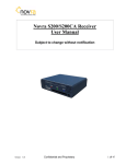
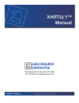
Stevens SatComm Product GUI Quick Start Guide Stevens Part #93876 June 2013 Contents 1. Product Overview.................................................................................................................................. 3 2. Opening SatCommSet ........................................................................................................................... 4 3. SatComm Setup Tabs ............................................................................................................................ 6 3.1 SatComm Setup Tab ............................................................................................................................ 6 3.2 Self‐Timed Setup Tab .......................................................................................................................... 8 3.3 Random Transmission Setup ............................................................................................................... 9 3.4 Comm Port Setup .............................................................................................................................. 11 3.5 DCP Setup .......................................................................................................................................... 13 3.6 Summary Tab .................................................................................................................................... 14 3.7 Uploading New Settings .................................................................................................................... 19 4. Going On‐Line ..................................................................................................................................... 21 Stevens Water Monitoring Systems, Inc. Page | 2 1. Product Overview The Stevens SatComm and SatComm With Internal Logger (Part #93876) is a NOAA/NESDIS certified 300/1200 baud 8PSK modulated transmitter used for relay environmental data from remote water monitoring stations. User‐friendly configuration, management, and data logging can be programmed through the included “SatCommSet 2.0” Windows GUI utility software, which has been designed for a quick and easy setup and deployment of the product. Once the SatComm transmitter or transmitter with internal logger is programmed, it can easily be placed “on‐line” and data is buffered for scheduled transmissions either from the internal logger version or from an external logger connected to the external logger interface connector. The purpose of this document is to be a quick start guide in using the GUI (graphical user interface) SatCommSet 2.0. If more instruction is needed, please refer to the SatComm User Manual, which goes into much more detail and focuses on the use of the terminal programming interface. For additional information about the Stevens SatComm, please visit the Stevens Water website or call Stevens at (800) 452‐5272. Stevens Water Monitoring Systems, Inc. Page | 3 2. Opening SatCommSet When you first open the Stevens SatCommSet 2.0 program the following window appears: This is the opening page that is where you make the Comm port and baud rate selection and connect to the SatComm. Click the “Refresh Com Port List” to see the USB virtual comm port you are using with your particular PC. At first the two squares labeled SatComm and Internal Logger will be grayed out. After a connection is made, if the unit is a SatComm with Internal logger, both squares will be highlighted. If the unit is a transmitter only, the internal firmware has tested for this and only the SatComm square will be highlighted, while the Logger side will still be grayed out. The next picture shows the same window after a connection to the SatComm (with internal logger) has been made: Stevens Water Monitoring Systems, Inc. Page | 4 Notice that now the SatComm and Internal Logger boxes are highlighted. Stevens Water Monitoring Systems, Inc. Page | 5 3. SatComm Setup Tabs Clicking on the SatComm box will open another window with 6 tabs, with the first tab selected, 3.1 SatComm Setup Tab SatComm Setup: In this window you will enter/choose: 1. 2. 3. 4. GOES Platform ID Antenna Type Cable Loss Password (if needed) You can click on “Upload Settings to SatComm” to retain the new settings at this point or you can wait until all the setting changes are made in all the tabs. At the bottom of this window is a feature that allows measurement of VSWR (voltage standing wave ratio). VSWR is a measure of the health of the connection of the SatComm transmitter to the cable and antenna. If the connection is good, it will show a low number (< 3.0). If the connection is unhealthy, then the number will be higher. VSWR numbers higher than 005.00 will result in the SatComm inhibiting the transmission until the connections are improved/fixed. The next screenshot shows a VSWR measurement: Stevens Water Monitoring Systems, Inc. Page | 6 When you click the “Get VSWR” button, the software will ask if your antenna and cables are connected. If you have not connected up your antenna at this point, please click NO. If you click Yes without connecting to a cable and antenna, then the SatComm could be damaged. When your antenna and cable are ready, click Yes and the measurement will be made and the value will be shown in the field: Stevens Water Monitoring Systems, Inc. Page | 7 3.2 SelfTimed Setup Tab Clicking on the next tab will open up a window used for setting all the parameters for Self‐Timed transmission: In this window you will enter/choose: 1. 2. 3. 4. 5. 6. 7. 8. 9. 10. Enable/Disable (by checking or unchecking the box) Self‐Timed Transmissions Transmission Baud Rate Channel Transmit Interval Timeslot (assigned by NOAA/NESDIS) Transmit Offset Message Format (ASCii or Pseudo Binary) Data Redundancy (used for sending the previous and current data set) Header Number (automatically set depending on Header Options selected, or manually set) Header Options The selection of baud rate will determine available channels and output power. Also note that if Data Redundancy is checked, then the amount of data bytes available to be buffered for transmission is cut in half. This is due to needing half of the timeslot for the previous data set. Stevens Water Monitoring Systems, Inc. Page | 8 If Header Options are used, they will be included in the payload of the transmission (before logger data). The software will show how many bytes are going to be used for the Header Options selected and how many are left over to be sent from a logger. When Header Options are selected, the Header Number will change automatically to indicate to the user at the receiver end that certain headers were used. You can override this automatic setting by selecting another number after selecting the header options. You can click on “Upload Settings to SatComm” to retain the new settings at this point or you can wait until all the setting changes are made in all the tabs. 3.3 Random Transmission Setup Clicking on the next tab will open up a window used for setting all the parameters for Random transmission: Stevens Water Monitoring Systems, Inc. Page | 9 In this window you will enter/choose: 1. 2. 3. 4. 5. 6. 7. 8. 9. Enable/Disable (by checking or unchecking the box) Random Transmissions Transmission Baud Rate Transmission Channel Transmit Interval Transmission Repeat Attempts Alarm Start Sequence Alarm End Sequence Message Length Timeout (sec). This is how long the unit wait to receive the End Sequence before concluding that it is normal data to be put into the standard buffer. 10. Message Format (ASCii or Pseudo Binary) 11. Header Number (automatically set depending on Header Options selected, or manually set) 12. Header Options Again, if Header Options are used, they will be included in the payload of the transmission (before logger data). The software will show how many bytes are going to be used for the Header Options selected and how many are left over to be sent from a logger. When Header Options are selected, the Header Number will change automatically to indicate to the user at the receiver end that certain headers were used. You can override this automatic setting by selecting another number after selecting the header options. Stevens Water Monitoring Systems, Inc. Page | 10 You can click on “Upload Settings to SatComm” to retain the new settings at this point or you can wait until all the setting changes are made in all the tabs. 3.4 Comm Port Setup Clicking on the next tab will open up a window used for setting all the parameters for setting up the Comm ports for SatComm: In this tab, the USB Virtual Comm Port and the External Touch Screen Port are fixed at 38.4K baud, 8 bits, no parity and 1 stop bit. The setting are just show as a reference, they cannot be changed. However you can change the external logger port settings. If an external logger is used, check the box “Enable External Logger Interface”. The above screen shot shows what the SatComm (without internal logger) will default to. You can adjust the Baud Rate, data bits, parity, stop bits and flow control. For Logger Flow Control, SatComm defaults to “Continuous Listen” mode. In this mode SatComm’s External Logger Port will always be “listening” for incoming data from the external logger. When it receives characters it places them into the standard transmission buffer (unless the Random start and end sequence characters are detected. In this case, the data is put into the Random buffer). Also, the CTS Wakeup (sec) field will be forced to “0”. Stevens Water Monitoring Systems, Inc. Page | 11 If you have a logger with CTS trigger capability you can select CTS trigger mode for flow control as a way to conserve power. If this mode is selected, the SatComm’s External Logger Comm port will be “asleep” until the scheduled transmission time. During this time, it will assert the CTS line of the RS232 port to be used to “wake up” the logger and “ask” for the logged data. The CTS Wakeup (sec) can be set for a specific number of seconds that the CTS line will stay asserted and allow data to come from the logger. After this time the CTS line will go “low” and the SatComm unit will store the data collected into the standard transmission buffer. Note: If CTS (Trigger Mode) flow control is selected, Random Setup will be disabled. The Random transmission feature can only be used when the Flow Control is set to Continuous Listen. The last selection is “Clock Sync”. This pull‐down menu is for use with some very specific loggers that customers requested their real time clocks to be synchronized to GPS (or UTC) time. The default is disabled unless the logger used is in the pull‐down list. You can click on “Upload Settings to SatComm” to retain the new settings at this point or you can wait until all the setting changes are made in all the tabs. Stevens Water Monitoring Systems, Inc. Page | 12 3.5 DCP Setup Clicking on the next tab will open up a window used for setting up the use of the DCP Command port: The original purpose of this port of the SatComm is for future use when the specification for the DCP Command is complete and ratified by NOAA/NESDIS. As of this writing, it is still “TBD”. For now we simply put a feature into SatComm that enables the DCP Command port to be used to echo logger data. This can be very useful when evaluating the connections to an external logger or when the user want to use another telemetry device along with SatComm, like Cellular. The default is the box is unchecked, but can easily be checked to enable this feature. You can click on “Upload Settings to SatComm” to retain the new settings at this point or you can wait until all the setting changes are made in all the tabs. Stevens Water Monitoring Systems, Inc. Page | 13 3.6 Summary Tab Clicking on the next tab will open up a window used for viewing the summary of the way the SatComm is configured: In this window, there are 4 fields and 6 buttons, all meant to show setup and diagnostics. The four fields show battery voltage, Internal temperature (internal to the SatComm) and Firmware Revision for both the main telemetry and I/O and failsafe processors. The four buttons just beneath the four fields show the following: Stevens Water Monitoring Systems, Inc. Page | 14 1. Hardware Status Hardware Status Results During power‐up, the SatComm does a built‐in self test (BIST). This result shows the list of items that are tested in BIST and whether they passed or failed the test. This can be useful to the end user who may be experiencing a problem and getting a lit RED BIST LED after the unit is powered. If the BIST LED is lit, the user can run this GUI press the “Save to File” button and save these results to be sent to a Stevens factory trained technician, who can use this information to help troubleshoot the problem. Note: Pressing the “Clear” button will erase any information that is presently inside the window. Note: Pressing the “Save to File” button will allow the user to save the information presented in the window. Be sure to do this before hitting the “Clear” button. Stevens Water Monitoring Systems, Inc. Page | 15 2. Get GPS Status GPS Status Results This button is useful in checking to see if the SatComm unit’s GPS receiver is working properly. It shows date and time, latitude and longitude, as well as number of Satellites being tracked and in view. This is very helpful information to help in the proper setup of the SatComm’s GPS antenna and cable. It will not be possible to go “On Line” with the SatComm unit until a GPS lock is obtained. This is a good place to check the progress of getting a “fix”. Note: Pressing the “Clear” button will erase any information that is presently inside the window. Note: Pressing the “Save to File” button will allow the user to save the information presented in the window. Be sure to do this before hitting the “Clear” button. Stevens Water Monitoring Systems, Inc. Page | 16 3. Get Channel Info Get Channel Info Results This button, when pressed, will show in simple list format how the Standard and Random Channels are setup. If you have made the changes in this tab, but have not done an “upload”, then the result will be how it is currently setup, which may be different than the way the user needs it. After uploading the settings, the user can press this button again and it should show the changes made during the setup process. Note: Pressing the “Clear” button will erase any information that is presently inside the window. Note: Pressing the “Save to File” button will allow the user to save the information presented in the window. Be sure to do this before hitting the “Clear” button. Stevens Water Monitoring Systems, Inc. Page | 17 4. Get Comm Port Info Comm Port Info Results Pressing this last button will show how each of the comm ports are setup. If you have made the changes in the Comm Port Setup tab, but have not done an “upload”, then the result will be how it is currently setup, which may be different than the way the user needs it. After uploading the settings, the user can press this button again and it should show the changes made during the setup process. Note: Pressing the “Clear” button will erase any information that is presently inside the window. Note: Pressing the “Save to File” button will allow the user to save the information presented in the window. Be sure to do this before hitting the “Clear” button. Stevens Water Monitoring Systems, Inc. Page | 18 3.7 Uploading New Settings After completing all of the necessary changes to the setup of the SatComm, press the “Upload Settings to SatComm” button at the top of the window. The software will confirm that this is what the user wants to do: If sure, click on “Yes”, else click “No” and continue to make changes to the setup. Stevens Water Monitoring Systems, Inc. Page | 19 After clicking “Yes”, SatCommSet confirms that the new setting were uploaded successfully: Click “OK” to continue. At this point you can select “File”, “Save” to save your configuration in order to use it again. This is handy when multiple transmitters need to be setup in the same way, or if the configuration gets lost and the unit needs to be setup again quickly. Stevens Water Monitoring Systems, Inc. Page | 20 4. Going OnLine Click the “X” in the upper right side of the window or select “File”, “exit” to close the SatCommSet setup window. This will take you back to the opening window: To go On Line, press the “Switch to Online Mode” button. Make sure that the GPS antenna is installed and positioned correctly. If you press this button without having a GPS fix, the following error message will appear: Stevens Water Monitoring Systems, Inc. Page | 21 Click “OK” and wait until you have a good GPS fix. When the GPS fix happens, the GPS LED will go out. Press the “Switch to Online Mode” button again (after getting a GPS fix) and the following messages will appear in the bottom window: Stevens Water Monitoring Systems, Inc. Page | 22 The last line “SATCOMM On Line Status: Confirmed” shows that SatComm is properly deployed. At this point, close the application and disconnect the PC from SatComm. Note: if power is removed after going OnLine, then re‐applied, the SatComm unit will do the following automatically: 1. Try to get a GPS fix. Once a GPS fix is done, the unit will: 2. Go back OnLine and resume scheduled transmissions. Stevens Water Monitoring Systems, Inc. Page | 23