1
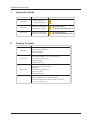
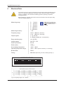
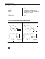
Vibration Control Type 663 Standard Zone-1-21 Zone-2-22 Instruction Manual English HAUBER-Elektronik GmbH Instruction Manual Vibration Control Typ 663 Standard Zone-1-21 Zone-2-22 Edition: 30.03.10 Attention! Before Start-Up Procedure the Instruction Manual must be read and understood! Should any question arise, please contact: HAUBER-Elektronik GmbH Fabrikstraße 6 D-72622 Nuertingen Germany Phone.: +49 (0) 7022 / 62393 Fax: +49 (0) 7022 / 64143 [email protected] www.hauber-elektronik.de HAUBER-Elektronik GmbH Content 1 Safety Informations................................................................................4 2 Instruction Manual Scope ......................................................................5 3 The Vibration Control Typ 663...............................................................5 Standard, Zone-1-21, Zone-2-22 4 Intended Use .........................................................................................5 5 Safety Level...........................................................................................5 6 Documents and Certificates ..................................................................5 7 Application Fields ..................................................................................6 8 Delivery Contents ..................................................................................6 9 Electrical Data .......................................................................................7 10 Mechanical Data..................................................................................8 11 Connections.........................................................................................9 12 Functional Description .......................................................................10 13 Limit Value Adjustment......................................................................11 14 Self Check .........................................................................................11 15 Mounting and Demounting ................................................................12 15.1 Fastening at the Mounting Surface ............................................................... 12 15.2 Zone-2-22 - Fastening Safety Clip / Protective Cover ................................... 13 16 Installation and Start-Up ....................................................................14 17 Maintenance and Repairs..................................................................14 18 Responsibility for the Safe Operation / Disclaimer ............................15 3 HAUBER-Elektronik GmbH 1 Safety Instructions In General The safety instructions serve the protection of persons and things from damage and danger that arise from not intended use and further misuse of products especially in explosion endangered areas. Therefore read the instruction manual carefully, before working with or starting-up the product. To the operating personnel the instruction manual has to be accessable anytime. Before the starting-up or miscellaneous works with the product please check, wether all the documents are available completely. If not all the documents are committed completely or futher copies are required, they can be obtained in different languages. Our product is designed to the latest state of the art. Nevertheless there are a number of residual risks. This means that each person in the operators firm, concerned with mounting and dismounting, installation, start-up, operating or maintanance of the product, has to have read and understood the instruction manual. This means furthermore that each person in the operators firm, concerned with mounting and dismounting, installation, start-up, operating or maintanance of the product, has to be an authorized expert, familiar with the safety instructions for handling electrical components. For handling ATEX-certified products within explosion endangered surroundings the expert in addition has to be familiar with the safety instructions relevant there. Used Symbols This symbol indicates an explosion hazard. This symbol indicates a risk from electrical current. This symbol indicates a (non-safety relevant) information. 4 HAUBER-Elektronik GmbH 2 Instruction Manual Scope The present instruction manual of the Vibration Control Type 663 is applicable for the variants: Standard, Zone-1-21 and Zone-2-22. The functionality of the variants is identical. In addition the variants have certifications and labellings, that allow operation in explosion endangered areas. (see chap. 7, Operation Areas) 3 Vibration Control Typ 663 The Vibration Control Typ 663 ist applied for measurement and control of machines absolute bearing vibration, referring to DIN ISO 10816. Measurement parameter is the root mean square (rms) of the vibration velocity. The evaluation takes place in two channels independent from each other. An exceeding of the adjustable Limit Value is signalled via relay outputs. This can be used to generate a pre- and a main alarm. In addition the Typ 663 has an analogue current output. This delivers a direct current from 4...20 mA proportional to the vibration amplitude. 4 Intended Use The Type 663 serves as protection for machines and mechanical equipment against undue mechanical vibrations. It exclusively serves for measurement of mechanical vibrations. Main areas of application: Industrial fans, ventilators, blowers, electric motors, pumps, centrifuges, seperators, generators, turbines, and similar mechanical equipment. 5 Safety Level The Type 663 is tagged by subsequent safety levels: - Safety Integrity Level, SIL2 / FMEDA, nach IEC 61508 - Performance Level, PL-d, nach DIN ISO 13849 6 Documents and Certificates Subsequent Type 663 Documents und Certifikates can be consulted on www.hauber-elektronik.de: EC-Conformity-Declaration Certificate - Safety Integrity Level, SIL2 / FMEDA Certificate - Performance Level, PL-d EC-Type-Examination-Certification ATEX-Zone 1 und 21, no.: SNCH 09 ATEX 4380 Statement-of-Conformity ATEX-Zone 2 und 22, no.: LU 09 ATEX 0065X 5 HAUBER-Elektronik GmbH 7 8 Application Fields Variant Application Fields Standard None explosion endangered Areas Zone-1-21 Explosion endangered Areas Zone 1 und 21 II 2G Ex d IIC T4 II 2D Ex tD A21 IP65 T120 °C Zone-2-22 Explosion endangered Areas Zone 2 und 22 II 3G Ex nC II T4 II 3D Ex tD A22 IP55 T125 °C Labelling Delivery Contents Variant Delivery Contents Standard • Vibration Control Typ 663 • Cylinder Bolt, M8 x 20 m m • Spring Ring, M8 • Ins truction Manual Zone-1-21 • Vibration Control Typ 663, with infus ed Cable, L= 2 m , 5 m oder 10 m , • Cylinder Bolt, M8 x 20 m m • Spring Ring, M8 • Ins truction Manual Zone-2-22 • Vibration Control Typ 663 • Protective Cover for M12-Plug • Safety Clip • Cylinder Bolt, M8 x 20 m m • Spring Ring, M8 • Ins truction Manual Available Supplies : • Allocable Mating Connector, M12, 8-pole 2 • Connection Cable, M12-Socket, 8-pole, 0,25 m m , L= 2 m , 5 m oder 10 m 6 HAUBER-Elektronik GmbH Electrical Data The housing cover may only be unscrewed, if the Type 663 is either seperated from the mains or no explosion endangered atmosphere exists. Otherwise danger of explosion because of sparkling, when the ATEX-certified Type 663 is operating in explosion endangered areas! Before Starting-Up Type 663, the mains must be secured with a microfuse (time delay, 160 mA, breaking capacity C)! Note: Each Type 663 has one of the listed measuring ranges. Further ones on request. Measuring range: 0... 8 mm/s 0... 16 mm/s 0... 32 mm/s 0... 64 mm/s 0... 128 mm/s 0... 256 mm/s Measuring accuracy: " 5% Frequency range: 10 Hz...1000 Hz (Standard) 1 Hz ...1000 Hz (optionally) Output signals: 1 x 4...20 mA 2 x Relay contact (Pre- and Mainalarm) Relay switching duty: 1A / 30V DC Voltage supply: 24V DC "10% Power input (max.): 80 mA Shock (max.): 1000 g Surroundings temperatur: -20°C...+60°C Operating temperatur range: -20°C...+85°C (Meas.-head-temp. a.t. fastening) Burden/load: 500 S Fusing: Microfuse (time delay, 160 mA, breaking capacity C) typical amplitude response of vibration velocity 10 5 0 dB 9 -5 -10 -15 -20 1 10 100 1000 Hz Fig. 1: Frequency range 10 Hz...1000 Hz Fig. 2: Frequency range 1 Hz...1000 Hz 7 10000 HAUBER-Elektronik GmbH 10 Mechanical Data Housing Material: Stainless Steel V2A; material no: 1.4305 M12-connector material: CuZn (brass), nickel plated Fastening: Inner hexagon screw, M8 x 20 mm Securing: The sensor must be earthed via the M8 fastening (see chapt.15). Weight: ca. 500 g Protection Style: IP 67 Housing Dimensions and Direction of Measurement Standard, Zone-2-22 Zone-1-21 Connection Cable M12-Plug Cable Gland Direction of measurement 30 Direction of measurement Measures in mm. Fig. 3: Housing Dimensions and Direction of Measurement: Standard, Zone-2-22 Fig. 4: Housing Dimensions and Direction of Measurement: Zone-1-21 Note: Direction of Measurement = Direction of Fastening 8 HAUBER-Elektronik GmbH 11 Connections Standard, Zone-2-22 Zone-1-21 M12-Plug Connection Cable 5 6 4 8 7 1 3 2 Fig. 7: PUR-sheathed-cable 8 -pole 0,25 mm². Pin allocation see Connection Plan. Fig. 5: M12-Plug, 8-pole. Pin allocation see Connection Plan. Connection Cable Socket (Supplies) Fig. 6: Connection cable socket M12, 8-pole, 0,25 mm². Pin allocation see Connection Plan. Connection Plan for all 3 Variants Vibration Control Type 663 1: white 2: brown 3: green 4: yellow 5: grew 6: pink 7: blue 8: red Fig. 8: Connection Plan Type 663 Note: Displayed in the Connection Plan is the Alarm Condition resp. Currentless Condition! The Relays 1 and 2 are dropped out. (Further informations on operating states, chap. 12) 9 HAUBER-Elektronik GmbH 12 Functional Description The housing cover may only be unscrewed, if the Type 663 is either seperated from the mains or no explosion endangered atmosphere exists. Otherwise danger of explosion because of sparkling, when the ATEX-certified Type 663 is operating in explosion endangered areas! The Typ 663 consistes of two channels LIM1 and LIM2 independent from each other. Both channels are constructed identically. For both channels the Limit Value and the Delay Time can be adjusted seperately. The exceeding of the adjustable Limit Value is signalled via relay outputs. This can be used to generate a pre- and a main alarm. In addition the Typ 663 has a analogue current output. This delivers a direct current from 4...20 mA proportional to the vibration amplitude. SET-Turn-Switch Limit Value in 15 Steps (Table: Limit Value, p. 11) ALARM - red WARNING - yellow OK - green Time-Potentiometer Delay-Time stepless, 0...30 sec. Fig. 9: User Interface Channels LIM1 and LIM2 Controls and LED-Indicators Operating Conditions Channels LIM1 and LIM2 Operating Condition OK WARNING ALARM Measurement < Limit Value > Limit Value, Delay Time running > Limit Value, Delay Time expired 10 Relais energized LED-Anzeige OK energized WARNING+OK dropped out ALARM HAUBER-Elektronik GmbH 13 Limit Value Adjustment Limit Value SETTurn-Switch Position Range 0…8 mm/s Range 0…16 mm/s Range 0…32 mm/s Range 0…64 mm/s 0 1 2 3 4 5 6 7 8 9 10 11 12 13 14 15 0 0,5 1 1,5 2 2,5 3 3,5 4 4,5 5 5,5 6 6,5 7 7,5 0 1 2 3 4 5 6 7 8 9 10 11 12 13 14 15 0 2 4 6 8 10 12 14 16 18 20 22 24 26 28 30 0 4 8 12 16 20 24 28 32 36 40 44 48 52 56 60 Range 0…128 mm/s 0 8 16 24 32 40 48 56 64 72 80 88 96 104 112 120 Range 0…256 mm/s 0 16 32 48 64 80 96 112 128 144 160 176 192 208 224 240 Example: Limit Value Adjustment Measuring Range e.g.: 0...32 mm/s SET-Turn-Switch Pos.: 8 Limit Value: 16 mm/s 14 Self Check Applying a rectangular signal (24 V DC / 0,5 Hz) at pin 4, the Typ 663 overall functionality can be checked. The test voltage simulates an vibration amplitude, that exceeds the maximum Limit Value step. To check the relays switch functionality the adjusted Delay Time has to be considered. U (V) 24 V DC t (s) Fig. 10: Self Check-Signal 11 HAUBER-Elektronik GmbH 15 Mounting and Dismounting Mounting and Dismounting works at and with the Control may only be executed by an authorized expert, familiar with the safety instructions for handling electrical components. For handling ATEX-certified controls within explosion endangered surroundings the expert in addition has to be familiar with the safety instructions relevant there. Before mounting and dismounting works the control has to be seperated from the mains! Seperated plug and socket devices always have to be disconnected from the mains! Otherwise danger of explosion because of sparkling, when operating ATEX-certified Types 663 in explosion endangered areas! The control housing must be earthed via ist fastening - i. e. via machine earth or via a seperate earth wire (PE)! 15.1 Fastening at the Mounting Surface Preconditions Mounting surface clean and flat, i.e. free from paint, rust, etc. Mounting Surface Threaded hole at the Mounting surface: Depth: 15 mm Thread: M8 Tools and Materials Allen wrench, SW6, SW8 Torque wrench SW8 Allen screw M8x20 Snapring for M8 Fig. 11: Fastening at the mounting surface Working Steps zu 5 Nm 1. Unscrew housing cover from housing base. Allen wrench, SW8 2. Fasten control friction-locked at the mounting surface by use of allen screw and snap ring. Allen wrench, SW6 3. Tighten housing cover on housing base loosely by hand. (Do not tilt the thread!) Tighten housing cover with a tightening torque = 5 Nm. Torque wrench SW8 Fig. 12: Tightening housing cover with a torque wrench Note: To avoid a possible galling of the housing cover with the housing base, it is recommended before the final mounting to treat the housing cover thread with a mounting paste for high-grade steel connections . 12 HAUBER-Elektronik GmbH 15.2 Zone-2-22 - Fastening Safety Clip / Protective Cover The operation of variant Zone-2-22 is not permitted without the safety clip, to avoid accidently disconnecting the plug-in connection! Otherwise danger of explosion because of sparkling, when operating in explosion endangered areas! Fastening Safety Clip 1. Plug in the connection cable socket into the M12-plug completely. (Pay attention to the code cam!). 2. Tighten firmly the lock-nut of the connection cable socket by hand. 3. Fasten the safety clip against accidental disconnection of the plug connection: 1. Put both shell halves of the safety clip around the plug connection. 2. Press together by hand both shell halves of the safety clip until the catch lock snaps in. 3. Put the arrow connected to one shell halve around the cable, then stick it through the eye on the other end, so that the notice sign is readable alongside the cable. Half Shell Arrow and Eye Sign Fig. 13: Safety Clip Fig. 14: Fastened Safety Clip Fastening Protective Cover After disconnecting the plug connection the protective cover has to be mounted! Disassemble the safety clip and mount the protective cover: 1. Disconnect mains / electric circuit. 2. Separate both shell halves of the fuse clip with a screw driver. 3. Fasten protective cover and skrew it tightly onto the sensor plug. Fig. 15: Protective Cover Fig. 16: Fastened Protective Cover 13 HAUBER-Elektronik GmbH 16 Installation and Start-Up Installing and starting-up the control may only be executed by an authorized expert, familiar with the safety instructions for handling electrical components. For handling ATEX-certified controls within explosion endangered surroundings the expert in addition has to be familiar with the safety instructions relevant there. Starting-up may only be executed with correctly tightened housing cover (tightening torque = 5 Nm)! Otherwise danger of explosion because of sparkling, when operating ATEXcertified Types 663 in explosion endangered areas! Prior to starting-up the Type 663, the mains must be secured with a microfuse (time delay, 160 mA, breaking capacity C)! The connection cable and possible extension cables must be protected against electrical influenzes and mechanical damages. Here local regulations and commissions absolutely have to be considered. 17 Maintenance and Repair Repairing the control may only be executed by an authorized expert, familiar with the safety instructions for handling electrical components. For handling ATEX-certified controls within explosion endangered surroundings the expert in addition has to be familiar with the safety instructions relevant there. Prior to repair and cleaning works the Type 663 has to be seperated from the mains! Seperated plug and socket devices always have to stay disconnected from the mains! Otherwise danger of explosion because of sparkling, when operating ATEX-certified Types 663 in explosion endangered areas! Defective connection cables immediately have to be replaced! Otherwise danger of explosion because of sparkling, when operating ATEX-certified Types 663 in explosion endangered areas! A defective control has to be changed completely! Note: The Type 663 and ist variants are maintenance free! Errortable Error Cause Activity No measured value (4-20 mA) No pow er supply Check pow er supply and/or connection cable Connection cable interrupted Relay does not sw itch Measured value w rong Replace connection cable Fuse defective Replace fuse Wrong connection cable polarity Provide correct connection cable polarity Type 663 defective Replace Type 663 Limit Value adjustement w rong Adjust Limit Value correctly No pow er supply Check pow er supply and/or connection cable Connection cable interrupted Replace connection cable Fuse defective Replace fuse Polarity of connection cable w rong Polarize connection cable correctly Type 663 defective Type 663 mounting not friction-locked Replace Type 663 Mount Type 663 friction-locked Type 663 mounting at w rong position Mount Type 663 at correct position 14 HAUBER-Elektronik GmbH 18 Responsibility for the Safe Operation / Disclaimer The correct layout of the electrical plant under conditions of explosion protection, as well as the correct switch on procedure, is the sole responsibility of the user of the plant. The current valid explosion protection rules and security regulations must be adhered to and must be under given circumstances checked by a competent person. Should the plant on the order of the user be erected by a subcontractor, the plant must only be switched on after the subcontractor has submitted an installation certificate as prove of the correct nature of the installation, according to the relevant valid regulations. The primary switch on of explosion protected plants or part of plants, as well as the subsequent switch on after major adjustments or maintenance work, must be reported to the relevant authorities by the owner. 15