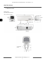
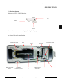
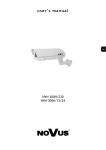
1
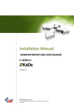
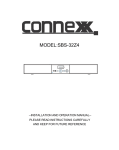
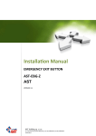
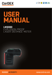
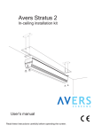
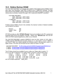
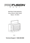
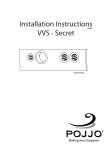
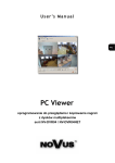
U s e r ’s m a n u a l
NVH-250H/230-II
NVH-250H/12/24-II
NVH-250H /230-II, NVH-250H/12/24-II – user’s manual, v .2.3
INFORMATION
EMC (2004/108/EC) and LVD (2006/95/EC ) Directives
CE Marking
Our products are manufactured to comply with requirements of following directives and national
regulations implementing the directives:
- Electromagnetic compatibility EMC 2004/108/EC.
- Low voltage LVD 2006/95/EC with further amendment. The Directive applies to electrical
equipment designed for use with a voltage rating of between 50VAC and 1000VAC as well as
75VDC and 1500VDC
WEEE Directive 2002/96/EC
Information for users who want to get rid of electrical and electronic appliances
This appliance is marked according to the European Directive on Waste Electrical and Electronic
Equipment (2002/96/EC) and further amendments. By ensuring this product is disposed of correctly,
you will help to prevent potential negative consequences for the environment and human health,
which could otherwise be caused by inappropriate waste handling of this product.
The symbol on the product, or on the documents accompanying the product, indicates that this
appliance may not be treated as household waste. It shall be handed over to the applicable collection
point for used electrical and electronic equipment for recycling purpose.
For more information about recycling of this product, please contact your local authorities, your
household waste disposal service or the shop where you purchased the product.
RoHS Directive 2002/95/EC
Out of concern for human health protection and friendly environment, we assure that our
products falling under RoHS Directive regulations, regarding the restriction of the use of hazardous
substances in electrical and electronic equipment, have been designed and manufactured in
compliance with mentioned regulation. Simultaneously, we claim that our products have been tested
and do not contain hazardous substances exceeding limits which could have negative impact on
human health or natural environment.
Information
The device, as a part of professional CCTV system used for surveillance and control, is not designed
for self installation in households by individuals without technical knowledge.
The manufacturer is not responsible for defects and damages resulting from improper, or inconsistent
with user’s manual, installation of the device in the system.
All rights reserved © AAT Holding sp. z o.o.
2
NVH-250H /230-II, NVH-250H/12/24-II – user’s manual, v .2.3
WARNINGS
ATTENTION!
THE KNOWLEDGE OF THIS USER’S MANUAL IS AN INDESPENSIBLE CONDITION OF A
PROPER DEVICE OPERATING. YOU ARE KINDLY REQUESTED TO FAMILIARIZE
YOURSELF WITH THIS MANUAL BEFORE STARTING THE DEVICE. THE MANUAL
SHOULD BE KEPT FOR FUTURE USE.
CAUTION!
ALL REPAIRS CAN BE EXECUTED ONLY BY QUALIFIED STAFF OF THE
AUTHORISED AAT Holding SERVICE.
CAUTION!
PRIOR TO UNDERTAKING ANY ACTION THAT IS NOT PROVISIONED FOR THE GIVEN
PRODUCT IN ITS USER’S MANUAL AND OTHER DOCUMENTS DELIVERED WITH THE
PRODUCT, OR THAT ARISES FROM THE NORMAL APPLICATION OF THE PRODUCT, ITS
MANUFACTURER MUST BE CONTACTED OR THE RESPONSIBILITY OF THE
MANUFACTURER FOR THE RESULTS OF SUCH AN ACTION SHALL BE EXCLUDED.
IMPORTANT SAFEGUARDS AND WARNINGS
1.
2.
3.
4.
5.
6.
7.
8.
9.
10.
11.
Read, keep, and follow these instructions. All the safety and operating instructions should be read
before the product is operated.
Heed all warnings. All warnings on the product and in the instruction manual should
be adhered to.
Follow all the safety instructions in this manual. Improper installation and camera operation may
have impact on operator’s safety as well as camera operational reliability and working life.
All the camera installations and operations should be done according to this user’s manual.
Unplug the unit before maintenance activities.
Use only attachments / accessories specified by the manufacturer.
To reduce the risk of fire or electric shock, do not expose this unit to rain or moisture as this unit
is designed for indoor use only. Do not install the camera near any heat source or near water (any
wet area).
Do not block any ventilation openings. All the installations have to be in accordance with the
manufacturer’s instructions.
Installation and servicing should be done only by qualified service personnel and conform to all
local codes.
This product should be operated only from the type of power a source indicated on the marking
label. If you are not sure of the type of power supplied to your location, consult your product
dealer. Do not overload power supply and extension cords as this can result in a risk of fire and/or
electronic shock. Use Certified/Listed Class 2 power supply transformer only.
Power cords and cables should be led in a way that protects them from being damaged.
All rights reserved © AAT Holding sp. z o.o.
3
NVH-250H /230-II, NVH-250H/12/24-II – user’s manual, v .2.3
WARNINGS
12.
For protection of the equipment during a lightning storm or when it is left unattended
and unused for long periods of time, unplug the unit. Disconnect any antennas or cable
systems that may be connected to the equipment. This will prevent damage to the
equipment due to lightning or power-line surges.
13. Do not overload wall outlets and extension cords as this can result in a risk of fire or
electric shock.
14. This unit is designed for indoor use only and it must not be exposed to rain or
moisture.
15. There are no user-serviceable parts inside this unit. Only authorized service personnel
may open the unit.
16. Unplug the unit and refer servicing to qualified service personnel under the following
conditions:
a.
When the power supply cord or plug is damaged.
b.
If liquid has been spilled or objects have fallen in to the unit.
c.
If the unit has been exposed to rain or water.
d.
If the unit does not operate normally by following the operating instructions.
e.
If the unit has been dropped or the cabinet has been damaged.
f.
When the unit exhibits a distinct change in performance - this indicates a need
for service.
17. Do not attempt to service the camera yourself as opening or removing covers may
expose you to dangerous voltage or other hazards. Refer all servicing to qualified
service personnel.
18. After any service operations test the camera and functionality of all camera
attachments / accessories .
19. The camera should be powered from the 24 VAC adapter. The adapter power required
for camera proper operation should be equal or higher than 20 W for camera module
only and 80 W for a camera with a fan and heater.
INFORMATION
Data included in the following user’s manual is up to date at the time of printing.
AAT Holding sp z o.o. holds exclusive rights to modify this manual. The producer reserves
the rights for device specification modification and change in the design without prior notice.
All rights reserved © AAT Holding sp. z o.o.
4
NVH-250H /230-II, NVH-250H/12/24-II – user’s manual, v .2.3
MAIN CHARACTERISTIC
1. MAIN CHARACTERISTICS
♦
External housing for compact cameras
♦
Die-cast aluminium costruction with powder coat stove finished, glass window
♦
Internal heater allows to operate in temperatures : from - 40°C to 50°C
♦
Heater power supply: 230VAC or 24VAC/12VDC, depending on model (housing
power supply information is definited in housing name after „/” mark)
♦
Degree of protection - IP67
♦
Mounting bracket included
2. PACKAGE CONTENTS
The package should contain the following elements:
Housing:
Bracket:
User’s manual:
Mounting screws:
Plastic anchores and screws for wall bracket mount
Isolation separator, isolation washer, camera mount screw
Allen L-Wrench
1pcs
1pcs
1pcs
4 pcs
3 pcs
1 pcs each
1 pcs
If the equipment has been damaged during transport or is incomplete, the contents of the
package should be packed back to the original box. Contact the local AAT Holding
distributor for further assistance.
3. SPECIFICATIONS
Housing model and type
Type
NVH-250H/230-II
NVH-250H/12/24-II
External for compact camera, bracket with cable channel
aluminum
Construction material
Colour
white
Heater
yes
Sunshield
yes
IP 67
Degree of protection
Power supply
12VDC / 24VAC
230 VAC
-40°C ~ 50°C
Operating temperature
Dimensions (mm)
450 (L) x 135(W)x 140 (H)
Internal space dimensions (mm)
250 (L) x 105 (W)x 80 (H)
Weight (with mounting bracket)
3,65 kg
housing, bracket, torx, screws, user’s manual
In set included
All rights reserved © AAT Holding sp. z o.o.
5
NVH-250H /230-II, NVH-250H/12/24-II – user’s manual, v .2.3
SPECIFICATIONS
3.1 Dimensions details
All rights reserved © AAT Holding sp. z o.o.
6
NVH-250H /230-II, NVH-250H/12/24-II – user’s manual, v .2.3
SPECIFICATIONS
3.2. Housing elements
Main parts of NVH-250H-II housing:
Top
Bottom
Bracket
Unscrew 4 screws to open housing by drawing back top part.
See picture below for parts lacation.
Thermostat board
Seal
Mounting base
screws
Moduł podstawy
Heater with metal
shield
Top/Bottom
connecting screws
Mounting base
Additional
connectors
Cable Channel
with clamp
All rights reserved © AAT Holding sp. z o.o.
7
Connectors board
Fuse
GND wire
NVH-250H /230-II, NVH-250H/12/24-II – user’s manual, v .2.3
SPECIFICATIONS
3.3. Electrical elements
Housing is equipped with a heater controlled by a thermostat. The heater task is to avoid steam
condensation on glass window. That’s why heater is located next to the glass window. Depending on
housing model, the heater operates with 230 VAC or 12VDC and 24 VAC. The heater is turned on by
thermostat when the temperature drops to 18˚C and turns it off when temperature reaches 25˚C.
Thermostat is located on thermostat bard. All electrical elements are connected by default. One
should connect power supply to additional connectors located in the rear part of the housing (starting
from glass window).
Refer to picture below
Thermostat board
Bottom part
GND of Bottom
part
GND of Top part
MARK
ELEMENT
H.1
Heater 230VAC or 24VAC/12VDC depending on model
STAT.1
Thermostat
TB.2
Additional connectors on thermostat board (V-IN)
FTB.1
N
E
L
Terminal connectors on terminal board, for hater connection;
- neutral or - 12VDC
- GND
- live line or + 12VDC
FS.1
fuse
TB.1
Additional terminal connectors for camera power supply etc.
CAUTION: Heater is a non-linear element. Power consumption of heater in steady-state is about
16W. Power consumption in starting stage (especially in low temperatures) may increase several
times.
All rights reserved © AAT Holding sp. z o.o.
8
NVH-250H /230-II, NVH-250H/12/24-II – user’s manual, v .2.3
MOUNTING
4. Mounting camera in housing
1.
2.
Select suitable mounting location and lead all cables near the bracket.
Mark mounting position and drill 3 holes for plastic anchors.
3.
Screw on bracket to the wall using 4 tapping screws witch plastic anchors.
4.
Unscrew 3 screws connecting parts of the housing with Hex L-wrench.
5.
Open the housing
6.
Feed on the necessary cables through the cable channel and screw on cable clamp
for cable channel sealing.
7.
Screw on housing to the bracket with 4 screws
8.
Connect housing power cables to terminal FTB.1 with proper polarization (refer to
previous page)
9.
Dismount mounting base (unscrew 4 screws)
10.
Screw on camera to the mounting base with additional skrew. Remember to use
isolation separator and isolation washer for camera isolation. Refere to Picture
below
Camera
Mounting base
Cross-section
Isolation separator
Mounting base
Isolation washer
Camera mounting
screw
The camera mounting place sholud be chosen depending on camera-lens length.
CAUTION: It is not advised to install camera-lens kit directly above heater shield. Heat
emited from the heater may cause grease evaporation from mechanical part of lens. It can
damage lens mechanism.
11.
12.
13.
14.
Screw on mounting base with camera to bottom part of the housing. Longitudinal holes
allow to set camera possition according to the heater.
Connect power and other necessary signals to the camera. Use TB.1 terminal
connectors.
Check and if necessary set lens focal length and sharpness
Close the housing.
All rights reserved © AAT Holding sp. z o.o.
9
NVH-250H /230-II, NVH-250H/12/24-II – user’s manual, v .2.3
AAT Holding Sp. z o.o.
ul. Puławska 431, 02-801 Warszawa
tel.: (22) 546 05 46, fax: (22) 546 05 01
www.aat.pl
2011-01-31 V. 2.3
All rights reserved © AAT Holding sp. z o.o.
10