1
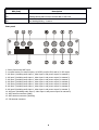
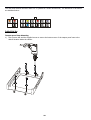
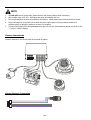
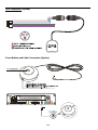
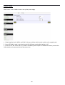
Bus-Cam® HD-4/8 High Definition Digital Video Recorder Installation Manual User Manual Thank you for choosing Bus-Cam HD-4/8 High Definition Video Recorder. This manual is applicable for both 4- and 8-channel disk models; the only difference is in the number of channels. Please read this Manual carefully to ensure that you can use the device correctly and safely. The contents of this manual are subject to change without notice. All Material is Copyright © 2015-2016 Robotics Technologies, Inc. All Rights Reserved. Warnings This device is NOT waterproof; to prevent fire or electric shock, please do NOT put any container with water on the device or nearby. Do not expose the device to moisture, or extreme temperatures. Important notice: 1 2 3 4 5 6 Please read over all precautions. Please keep this manual for future reference. Please note all warning information. Please strictly follow the instructions in this manual while operating. NEVER locate or operate this device in a wet environment. Please do NOT use abrasive chemicals, cleaning solvents or strong detergents to clean the unit. Wipe with a soft and dry cloth. 7 Please do NOT block any ventilation openings. 8 Please keep the device far away from hot and high temperature environments. 9 Install the device with the included accessories. 10 Please take care to secure the device properly, and avoid dropping from a high place. 11 Call for qualified service personnel when repairs are needed. 12 The HD-4/8 can only be installed horizontally. Installing vertically or out of the horizontal could injure personnel or damage the device and/or its components. 2 Table of Contents WARNINGS...................................................................................................................................................................................... 2 INTRODUCTION................................................................................................................................................................................. 5 Product Description....................................................................................................................................................................5 Standard Components and Features..........................................................................................................................................5 Optional Components and Features...........................................................................................................................................5 PRODUCT MAIN FEATURES...................................................................................................................................................................5 VIDEO AND AUDIO............................................................................................................................................................................ 5 GPS TIME SYNCHRONIZATION & TIME ZONE............................................................................................................................................5 POWER MANAGEMENT....................................................................................................................................................................... 6 RECORDING MODE............................................................................................................................................................................. 6 SPEED AND VEHICLE STATUS RECORDING.................................................................................................................................................. 6 G-SENSOR....................................................................................................................................................................................... 6 HARD DISK...................................................................................................................................................................................... 6 SD CARD......................................................................................................................................................................................... 6 MULTIPLE MEDIA PLAYERS SUPPORTED....................................................................................................................................................6 PRODUCT IMAGES.............................................................................................................................................................................. 7 Front Panel.................................................................................................................................................................................7 FRONT PANEL LEDS........................................................................................................................................................................... 8 Display the Status of the HD-4/8................................................................................................................................................8 Rear panel..................................................................................................................................................................................9 INITIAL SET UP............................................................................................................................................................................... 10 Tamper-proof Case Mounting..................................................................................................................................................10 POWER CONNECTIONS...................................................................................................................................................................... 12 Use the Ignition Switch to Activate Recording.........................................................................................................................12 Record Automatically Upon Power-up.....................................................................................................................................12 CAMERA CONNECTIONS.....................................................................................................................................................................13 SENSOR HARNESS CONNECTION.......................................................................................................................................................... 13 GPS CONNECTION (OPTION)............................................................................................................................................................. 14 EVENT BUTTON AND CABLE CONNECTION (OPTION).................................................................................................................................14 CONNECT THE HD-4/8 TO A PC USING A NETWORK...............................................................................................................................15 Download and install the VLC player into your computer........................................................................................................15 Connecting the HD-4/8 to Your Network.................................................................................................................................15 Use a Web Browser to Access Live View or Menu Settings......................................................................................................15 BASIC OPERATION AND MENU SYSTEM................................................................................................................................................. 16 Hard Disk Formatting...............................................................................................................................................................16 To format:.................................................................................................................................................................................16 RECORDING SETUP...........................................................................................................................................................................17 CAMERA SETUP...............................................................................................................................................................................18 ALARMS SETUP............................................................................................................................................................................... 19 MOTION DETECTION SETUP............................................................................................................................................................... 20 POWER SETUP................................................................................................................................................................................ 21 VEHICLE PARAMETER SETUP............................................................................................................................................................... 22 3 GPS PARAMETERS SETUP (IF EQUIPPED)................................................................................................................................................23 G-SENSOR PARAMETER SETUP............................................................................................................................................................ 24 SCHEDULE RECORDING SETUP.............................................................................................................................................................25 NETWORK SETTINGS.........................................................................................................................................................................26 3G NETWORK SETUP (IF EQUIPPED).....................................................................................................................................................27 DATE AND TIME SETUP..................................................................................................................................................................... 28 UPGRADE THE FIRMWARE.................................................................................................................................................................. 29 RESET THE HD-4/8.........................................................................................................................................................................30 USER MANAGEMENT........................................................................................................................................................................30 SPECIFICATIONS............................................................................................................................................................................... 31 LIST OF STANDARD ACCESSORIES..........................................................................................................................................................33 TROUBLESHOOTING.......................................................................................................................................................................... 34 4 Introduction The Bus-Cam HD-4/8 series mobile digital video recorder is a compact, full-featured H.264 1080p/720p recording system that uses a hard disk as a storage device. The recorder unit and associated accessories are specifically designed for operation in a mobile environment. The HD-4/8 system, used in conjunction with the cameras, records up to eight channels of full-motion video and audio data to a hard disk. The firmware-driven menu system provides a simple method for configuring the unit’s operation as well as searching for and viewing previously recorded AV records. Product Description The HD-4/8 unit consists of the following major components: Standard Components and Features Extruded aluminum case (the case is anodized in black). Front and rear panels. Motherboard. Power cables. Power input 2 amp fuses (2). Tamper proof and lockable security enclosure. Panel lock with (2) keys for locking the security enclosure. Hard disk or Solid State Disk (customer supplied). Removable SD card, Class 10, minimum (customer supplied). Optional Components and Features GPS speed and location data overlay. Extension cable for easy connection and installation. Product Main Features Embedded operating system, assuring reliability and system integrity. Records up to four/eight channels of full-motion color video with corresponding audio tracks. H.264 High Profile video compression. Total Recording resource up to 120 1080P frame/second. Lockable security enclosure. Front panel USB2 port for recording to a flash card as an optional storage device. Ignition sense that provides DVR power-on in recording mode when the vehicle is started. Power-off delay record when the vehicle is shut-down, with operator-selected delay times. Video And Audio H.264 High Profile video compression, real time recording 1080p30, 720p30 and 540p30 for each channel. Frame rate adjustable for each channel. Audio compression:16bit 48KHz AAC codec. This codec offers high compression with high quality audio. 1080P resolution for each channel, which means each channel supports 1920x1080 @30fps. Supports 4/8 channels real time 1080P video and 4/8 channels audio recording. Real time live HD video and audio through WiFi, supports Windows, Android and iOS Recorded HD video and audio real time playback over WiFi 5 GPS Time Synchronization & Time Zone Synchronizes the DVR system time with GPS automatically Supports All Time Zones Worldwide Supports DST (Daylight Saving Time) Power Management Reliable power management, wide voltage: +8V~+32VDC; The power input is protected against short positive transients (1500 watts peak pulse power capability with a 10 x 1000 uS waveform); The power input is protected against negative voltage. Applicable for vehicles with +12V or +24V battery. The recorder provides each camera with stable +12V DC power; the DVR can detect short circuits in the power supply. Can use ignition to control the power. DVR can monitor battery voltage after Ignition off, and automatically enter sleep mode when the voltage is below a reliable operating level. Recording mode Continuous record. Supports schedule recording. Supports alarm recording. Speed and Vehicle status recording Record vehicle speed and vehicle ID with audio and video. Supports 5 sensors: Can be connected to speed, ignition, brake, backup, right turn, left turn light etc. Over-speed alarm and trigger recording with separate log files G-Sensor X, Y, Z axis accelerometer Recorded G-Sensor Values can provide reference for data analysis in accident re-creation Combined Recording can be triggered when G-Sensor values go beyond a preset threshold Hard Disk Supports hard disks up to 2 Terabytes. Note: The inside height of the hard disk case is 0.40”. Choose a drive with maximum height less than 0.375”, for proper fit. SD card Supports SDHC card within 32GByte. Supports SDXC card more than 64GByte (Maximum 2048GByte) Supports hot-plug when the DVR system is not recording or remote-operation (remote copying or playing back) Note: Removing the SD card during recording or operating (remote copying or playing back), could corrupt the SD card. While recording, the yellow light on the front panel will be on. Make sure that the Yellow Light is off before removing the SD Card. Multiple Media Players supported You may use our PC Playback Software or any of the following third party (free) media players to play back the recorded files. VLC media player (version1.0.0 or above); Storm player (Version 2009 or above); WinAmp (Version 5.531 or above). 6 Product Images Front Panel 1: USB Host Port: Can be used as a secondary recording device, such as a flash memory card. This port cannot be used as a direct access link to a PC, however. 2: SD Card Slot 3: Stop Button: To stop recording 4: 3G Status indicator 5: For inject the SIM card 6: SIM Card Slot (Only for models support 3G/4G) 7: LANC Port: For connection to an Event button and status indicator Network Port (RJ45). 8: Status Lights (1: Power; 2: Run; 3: Alarm; 4: Record; 5: System) 9: Lock and power switch for the Hard Drive (must be locked to record) 10: Hard drive tray 11: LAN port (RJ45) 7 Front Panel LEDs Display the Status of the HD-4/8 System (Yellow) Status / Description Solid On All channels are recording Blinking Interval of 2-seconds: The number of flashes within the interval indicates the inactive camera count. For example, 3 blinks per interval = 3 inactive cameras. Off No active cameras / Not Recording 3G (Yellow) Status/Description On 3G mode is working normally. Blinking No SIM card, or no 3G service Off No 3G module installed (3G is not available) PWR (Green) RUN (Green) Status/Description Always On Blinking DVR is on & running Blinking with RUN by turns Blinking with PWR by turns Ignition is not enabled and DVR is OFF. Blinking together with RUN Blinking together with PWR Ignition sense is not enabled & DVR is running. Unit will turn OFF when “Delay Time” setting is reached. Blinking every 3 seconds Off Use the key to turn off the DVR. ALARM (Red) Status/Description On Alarm input when BEEP is set as “ON”. Audible alarm (beep) when enabled. Off No alarm. 8 REC (Red) Description On Reading/Writing data from/to the hard disk or SD Card. Off Not Reading/Writing – inactive. Rear panel 1: Power, Ground and ACC input. 2: 1x speed sensor, 3x sensors inputs, 1x RS232 port(for GPS) and 1x 5V DC output 3: AV input 1(including audio input 1, video input 1 and power output for camera 1) 4: AV input 2(including audio input 1, video input 1 and power output for camera 2) 5: AV input 3(including audio input 1, video input 1 and power output for camera 3) 6: AV input 5(including audio input 1, video input 1 and power output for camera 4) 7: AV input 6(including audio input 1, video input 1 and power output for camera 5) 8: AV input 7(including audio input 1, video input 1 and power output for camera 6) 9: AV input 8(including audio input 1, video input 1 and power output for camera 7) 10: AV input 4(including audio input 1, video input 1 and power output for camera 8) 11: WiFi antenna connector (Main) 12: WiFi antenna connector (Auxiliary) 13: 3G antenna connector 9 The rear panel sockets are Molex Micro-Fit 3.0 (Model No.: Molex 0430450200). The definitions of all sockets are indicated below: Initial Set Up Tamper-proof Case Mounting 1) Use a power drill and the supplied screws to secure the bottom cover of the tamper-proof case to the desired location inside the vehicle. 10 2) 3) Place the DVR system into the bottom cover, and load a hard disk. Close with the top cover and lock it with the supplied keys. 11 Power Connections Use the Ignition Switch to Activate Recording Record Automatically Upon Power-up 12 NOTE 1 2 3 4 5 The HD-4/8 uses DC power only; please observe the proper polarity when connecting. Safe voltage range is 8V-32V. Exceeding this range can damage the unit. The power should be as direct as possible to the battery. Avoid sharing with solenoid and motor loads. Power consumption of the DVR can be 60W when the engine starts. All power cables should be of sufficient gauge to provide a minimum current of 5 Amperes. To protect the battery from being damaged from short circuit, the fuse should be placed very close to the “+” pole of vehicle's battery. Camera Connections Connect cameras to the HD-4/8 with the provided AV cables. Sensor Harness Connection 13 GPS Connection (Option) Event Button and Cable Connection (Option) 14 Connect the HD-4/8 to a PC Using a Network Download and install the VLC player into your computer You will need to install a VLC player to play back the video from the DVR. The VLC player is available at: ftp://ezview.3322.org/DVR/HDVR/vlc-2.0.1-win32.exe. After installation, the VLC plugin will be available for your internet browser. It supports IE, Chrome and Firefox. Connecting the HD-4/8 to Your Network 1) Connect the DVR via Network Cable: Set your PC to use a dynamic IP address (DHCP). The HD-4/8 AP will assign a new IP address for your computer. 2) Connect the DVR via WiFi: To use WiFi, you can scan and find an AP with name of "HDVR_****", then connect it. Make sure to set your computer to use a dynamic IP address (DHCP); the HDVR’s AP will assign a new IP address automatically. Use a Web Browser to Access Live View or Menu Settings Please enter "hdvr.cfg" or "192.168.10.254" in the address bar of your web browser; the browser will request permission to use the VLC plug-in, so check the “yes,” to view 4 images in quad mode. 1) On the Live View page, please click the button Cam1, Cam2, Cam... for each camera's HD image (1080p/720p). 2) If you want to change settings, please click the “SETTINGS” tab. 3) If a camera is recording, its corresponding red dot will blink. 15 Basic Operation and Menu System Hard Disk Formatting A brand new disk may require formatting before using it in the HD-4/8. To format: 1) Put the hard disk into the hard disk case, insert it and lock it into the DVR, then power up. 2) Click “SETTINGS” and choose “Storage” in the “System” menu; a) b) c) d) e) f) Click “Format” to format the hard disk. Formatting storage media will result in loss of all data on the disk, so back up your important files before formatting. The format process will take some time--please be patient. You will see the capacity of the hard disk after formatting. The oldest video files will be deleted automatically when the storage media gets full if "Memory Auto Overwrite" is checked. Alarm record files under the "Alarm" directory can only be deleted manually. "Memory Disk Contents" will list all the folders and files on the storage media in chronological order. Clicking "View" to download any designated file or explore the details in the folder 16 Recording Setup Click “Record Details” in the “DVR” menu to set up your recording. 1. Each camera supports up to 1080p30; bitrate varies from 100Kbps to 8000Kbps. Default setting is 1080p30 with a bitrate of 3000Kbps. 1200Kbps is recommended for 720p25. We use intelligent bitrate control to save media space when performing H.264 image compression. If no obvious movement is in frame, the bitrate will be reduced to 50%(75% for 1080p) of the set value automatically. For example, if one camera is set to 720p 25 at 1200Kbps, the actual running bitrate could be 600Kbps when no obvious movement occurs within frame. 2. Three levels of resolution supported for recording: 1080p(1920x1080), 720p(1280x720) and 540p(960x540). If you need more recording time with the same SD card size, you can select 720p or 540p for recording, or use a lower frame rate or bitrate with acceptable video quality. 3. An SD card with speed of Class 10 is required for high bitrate settings. 4. Estimated recording time with the storage media being used will be displayed within the configuration box. You are allowed custom settings for resolution, bitrate and frame rate on each individual camera. Note: The estimated recording time depends on the complexity and extent of movement. 5. File length can be optional from 1 min to 4 hours. The size for a single file should not be over 2GB with limitation of FAT32. That means the file size will be limited as 2GB or less to avoid file system error, even it does not reach the set record time (when high bitrate and/or long file length is set). 6. Supports 3 record modes: Manual/Auto/Off. Default is Auto. Manual: Send commands from the management page, IE. Mouse click on Start button. Auto: Record automatically after trigger. Off: Any camera set to "Off" will have recording disabled. 7. Support 3 record modes: Manual/Auto/Off. Default is Auto. 8. Click Start/Stop to start or stop record on each individual camera. Click "Apply" to have the setting change(s) take effect. choose ”RECORD” to enter its sub-menu; 9. The recorded file can be encrypted. You may just check the ”Using Encryption” to enable this feature. The encrypted file can be played only on our special AVPlayer. 17 Camera Setup Click “Camera Setting” in the DVR menu to setup the cameras. 1. Click CAMx to adjust each camera's brightness, contrast, audio volume, and other settings. 2. Max 12 characters is allowed for each camera title. 3. Camera image can be flipped in horizontal or vertical direction. 4. Enabling “Auto Black-and-White” will toggle from Color Mode to Black & White Mode, or from Black & White mode to Color Mode automatically according to the camera light sensor device. 18 Alarms Setup Click “Alarm Details” to set up alarm actions. 1. 2. 3. 4. 5. 6. 7. Alarm setting includes 3 external triggers and 1 event button. External triggers can be set with high-level active or low-level active. An Event button can be used to start/stop recording, or trigger an alarm recording. Combined Recording can be triggered when any alarm happens. The image on screen display characters can be edited in Alarm OSD menu. Pre-record and Post-record times can be set for the alarm triggered record file. Alarm record files will not be deleted, even the disk is full and Overwrite option is ON. 19 Motion Detection Setup Click “Motion Detection” to set up Motion Detection alarm. 1. Up to 12 motion detection areas can be activated for each camera. 2. Each camera needs to be configured individually. 20 Power Setup Click “Power” in the “Mobile” menu to set up the power supply. 1. Default ignition level is HIGH, and LOW for the rare vehicles with the main switch on the negative pole. 2. Power Off Delay is used to set how long the HD-4/8 keeps running after ignition is off. 3. "Power On At" and "Power Off At" is used for scheduling Power On/Off. To enable this function, connect the Yellow ignition wire connected to the Red power wire. 21 Vehicle Parameter Setup Click “Motor” in the “Mobile” menu to setup vehicle parameters. 1. 2. 3. 4. Speed is obtained from GPS (if so equipped). The item "Speed Limit" is used to set the speed alarm threshold. Combined Recording can be triggered when over-speed. Image on-screen display characters can be edited and applied when over speed. 22 GPS Parameters Setup (if equipped) Click “GPS” in the “Mobile” menu to setup the GPS parameters. 1. GPS Status: GPS NOT FOUND: No GPS detected. GPS DATA: GPS is found, but data stream error (baud rate or protocol error). GPS GPRMC: GPS GPRMC means correct, but inactive GPRMC frames. (GPS searching is in process, or GPS signal is weak or lost) 2. GPS OSD enables/disables the display of longitude/latitude data within the video image. 3. Sync with GPS Time provides the option to synchronize the system time with GPS time. 4. System time will be synchronized with GPS time every hour if sync option enabled, and only minutes and seconds will be synchronized. If you want to set date and hour, please reference "Date and Time" menu. 23 G-Sensor Parameter Setup Click “G-Sensor” in the “Mobile” menu to set up the G-Sensor Menu. 1. G-Sensor Instant Value can give the X/Y/Z axis accelerometer values instantly. 2. For Earth gravity effect, it will display about 1.0g on Z axis when the DVR is placed on a horizontal surface. 3. Initial values should be set to the X/Y/Z axis values when the vehicle is still, and DVR is installed on desired position. 4. Alarm Threshold can be set to the absolute differential value between initial value and acceptable maximum value. If the absolute difference exceeds the threshold, a corresponding axis alarm will trigger. 5. Combined Recording can be triggered when a G-Sensor Alarm occurs. 6. Recorded G-Sensor Values can provide data analysis for accident re-creation. 24 Schedule Recording Setup Click “Record Schedule” in the “DVR” menu to setup schedule record. 1. The record schedule allows for 3 time plans per day. 2. Each camera can be scheduled individually, or click "All" to apply the same recording schedule to all cameras. 25 Network Settings Click “WiFi network” in the “Network” menu to set up the network. 1. The HD-4/8 can work in both WiFi AP and WiFi Client mode: I. AP Mode WiFi AP can be turned ON or Off with the checkbox. Local SSID can be renamed, ie. Vehicle Plate Number. WiFi Channels should correspond with the Country Region. Encryption mode should be selected when a WiFi password needed. II. Client Mode WiFi Client can be turned ON or Off with checkbox. Use "Wireless Scan" to show the available remote WiFi AP list. Click the remote WiFi AP which the DVR want to connected. Enter the password as mentioned to connect. Default IP mode is DHCP, Static IP address mode is also available. 2. Click the "Apply" button when all of the settings are completed. The WiFi will restart and enforce the new settings. 26 3G Network Setup (if equipped) Click “3G Network” and “Network Settings” in the “System” menu to setup your 3G Network. (3G functionality is only available with HD-4/8 with the 3G/4G option) 1. 3G Status: 3G NOT FOUND: 3G module is not detected by DVR. 3G LOADED: 3G is loaded without service (SIM card error or no RF signal). 3G CONNECTED: 3G module works properly. 2. Make sure that your SIM card is correctly inserted (Keep the side with metal pads down) 3. Intelligent devices (PC, Pad or Phone) connected to DVR can access internet when 3G is Active. 27 4. When needed, get APN & Password from you local 3G service provider. 5. “Network InUse”: The DVR can communicate with server by WIFI or 3G/4G network. WIFI network always has the priority. 6. Server Status: When WIFI or 3G/4G is connected with server, it shows “Connected”. When none of WIFI or 3G/4G is found, it shows “Disconnected”. 7. Select a suitable Resolution, Bitrate and Frame rate for the according camera. 8. Use higher Bitrate and Lower Frame rate to get better image quality. 9. "Plug and Play" is not supported for 3G SIM card. When inserting or changing a new SIM card, the DVR needs to be rebooted. Date and Time Setup Click “Date & Time” in the “System” menu to set up date and time. 1. Manual Setting and Sync with PC Time are the two ways for adjusting time. 2. Intelligent Device (PC, Pad or Phone) connected to DVR can sync its time to DVR system time by enabling "Sync with PC time". 3. The item "Time Zone" is used to select the according time zone in your area. 4. The item "DST Setting" now is only useful for three countries: USA/Australia/New Zealand. 28 Upgrade the Firmware Click “Upgrade” in the “System” menu to upgrade the firmware of the HD-4/8 or Cameras. 1. System Version includes: DVR Kernel Version DVR App Version MCU FW version Web Menu version Camera FW version 2. The Upgrade file should have a file type of “ .tar.” 3. You will be notified upon completion of the Upgrade. 4. Restart the browser or clear the web cache if necessary. 29 Reset the HD-4/8 Click “Reset” in the “System” menu to Reset your HD-4/8. The HD-4/8 can be reset to “Factory Setting” for all settings. You can also reboot the unit in this menu. User Management Click “User Management” in the “System” menu to set the user authority for the HD-4/8. Admin has all authorities to configure or change settings. Other levels of user can only watch the live video, and review the record files. 30 Specifications Model System BD-313 Operating System Linux 2.6 Start-up Time <20 seconds (From power on to recording) Operator English / Simplified Chinese / Russian / Others on Request Interface Storage 2.5” Hard Disk(up to 2TB), SSD(up to 2TB) or SD Card (up to 128GB) Video System H.264 Main/High Profile, HD 1080p30/720p30/540p30 Recording for each channel Voltage Input & Input: 8 V ~ 32 V DC, Output: 12V/1.5A (4 channels) Output Video Video Input Maximum 4 to 8 x 1080p / 720p camera inputs (model dependent) Video output PC / Notebook / iPhone / iPad /Android Pad / Android Phone Preview 1 image / 4 images (Switch for 8 images) Standard Stream ISO 14496-10 Recording Selectable (1920x1080, 1280x720, 960x540) Resolution Recording Supports normal, schedule, alarm recording and continuous Video H.264 (High profile up to level 4.1) Compression Audio Max fps (total) 240fps@1080p for 8 channel model / 120fps@1080p for 4 channel model Audio Inputs From Maximum 4/8 Cameras (model dependent) Audio AAC (16bit, 48KHz) compression Interface I/O LAN 1 (RJ-45) 10M / 100M Ethernet port USB Supports USB 2.0 for U-Disk recording Serial RS-232 × 1 31 Network Alarm & WiFi Built-in 802.11b/g/n Access Point, with speed up to 300Mbps Protocol TCP / IP Comm. 4G/3G (Only for models that support 3G/4G) Inputs 3 Alarm input, 1 speed, 1 ignition, 1 Panic button, G-Sensor Outputs 1 Beeper, Alarm LED, Email Multi-mode Activated by video loss, maximum preset speed limit, collision, SD space, Sensor video motion, etc. Power Supply Ignition key Recording starts when ignition is on, stops with delay time when ignition is off. Power Average 2.0W (DVR w/o SD/SSD/HDD or cameras connected) Consumption Physical Dimensions 5.60” x 5.20” x 1.18” (143.3mm x 133.0mm x 30.2mm) Weight 2.4 lbs. (1.08kgs) Backup Via WiFi (300Mbps, actual download speed up to 150Mbps) Clock Internal, permanent calendar, Time sync from GPS (if available) GPS GPS/GLONASS external module Function Dual Allows you to configure the rate of different transmission frame rate Streaming recording / bandwidth control Self-protection Protection against overload, short circuit and reverse polarity Reset Option to return to factory default settings SD memory Supports SD card x 1 (supports SDXC, up to 128GB) LED’s Indicates Power, RUN, Alarm, Media Access, Recording status, network and Characters Others 3G Writing and Overwrite ON/OFF selectable reading of data Synchronization GPS Time Synch / NTP (Network Time Protocol) Time Synch via networking time 32 Environment Operating -22°F to 140°F (-30°C ~ 60°C) Temperature Relative humidity 5% - 95% Vibration < 3G rms resistance Resistance to < 1200G rms mechanical shock Embedded Configure FPS per Software channel ID records vehicle Allows (1~30fps) allowed license plate USB Record and update firmware Rename channels allowed Watermark fixed Schedule Settings: Hour, minute, 3 time plans per day Image Playback Includes date and time, latitude*, longitude*, vehicle speed*, vehicle ID plate and name or channel number (* requires GPS option) Playback Speed Speed forward, variable 1x ~ 16x List of Standard Accessories Item Description Quantity 1 HD-4 or HD-8 One 2 Tamperproof Lock Case One 3 Lock case key Two 4 WiFi Antenna Two 5 Signal cables One 6 Power cable One 33 7 Fuse box One 8 3A fuse Two 9 User’s Manual One 10 3G Antenna One (Only for models supporting 4G/3G) Options: Item Description Quantity 1 External GPS Receiver One 2 Event Button & Cable One 3 Extension Cable (3m, 6.2m, 10m Option) One per camera 4 Hard Disk One 5 Hard Disk Reader One 6 Anti-vibration case One Troubleshooting 1. Q: After connecting the DVR power, no WiFi AP SSID is available. No. 5 and 6 indicator lights are flashing alternately. A: The No. 5 and No. 6 LED indicator lights are “Power” and “Run”. If the 2 indicator lights are flashing alternately, then the ignition signal is absent. Please check that the yellow wire of the input power cable is connected with the power positive level, or if it’s the same as the setting of the effective electrical level in menu settings. (Default setting is high-activate – that is, it is active when the yellow ignition signal line is connected to the positive potential.) 2. Q: Since hard disk capacities are finite, how can I increase recording time to meet the my requirements? A: Reduce the video frame rate, resolution and bit rate, please see 5.2. 3. Q: What is a high level, what is a low level? A: Generally, there are two electrical levels in a vehicle, the power and the ground. Automotive power voltage with 12V and 24V, is generally called “high level,” not a specific voltage value. Vehicle Ground is the reference level--usually the battery negative electrode (the low level). For cars with negative power supplies (rare in the US) the chassis ground is not a reference ground. Please see the Appendix, including the potential analysis diagram for vehicles with negative power supplies. 34 4. Q: Respectively, what’s the voltage reference range of the high and low level in the DVR? A: The voltage range for low level is 0VDC to 3VDC, the high level is 6VDC to 32VDC. Never exceed the power supply voltage on any signal input—damage can occur. 5. Q: My SD cards or hard drives are OK, but video recording doesn't work, what should I do? A: Make sure that the default setting of Record Mode is changed from "Automatic" to" Off ", and confirm that the current time is within a scheduled record time (if any schedule is set). 6. Q: Is the internal real time clock of the DVR maintained by a battery? If so, how long will it last? A: A rechargeable battery is used for DVR internal real-time clock. If the battery is fully charged and DVR is completely disconnected from the power supply, the internal real time clock can last for approx. 1 month. If GPS is present, Sync with GPS Time gives the option to synchronize the DVR system time with GPS time. 7. Q: What do the 6 indicator lights representative on the panel of the DVR? A: Please refer to the descriptions in 2.1 8. Q: What kind of player software is used to play back video clips in SD card on my PC? Why don't some of them play normally? A: The DVR recording files are in a standard AVI format, video stream compression standard is high profile H. 264. 1. The DVR has its own player software, including many special additional features, such as playing continuously, fast forward playing, and ability to quickly locate recorded clips. 2. The recorded files also support such general players as VLC (version 1.0.0 and above), Media Player Classic (version 2009 Build: 3.9. above), or Storm Audio. They are freely downloadable from the internet. 9. Q: How do I upgrade the DVR program? A: Please refer to the instructions in section 5.11 10. Q: Do your DVRs have RS485 control PTZ functions? A: The DVR will not support PTZ directly. Traditional RS485 is not supported in the High Definition Video System. PTZ implementation mode is like an IP Camera; our upcoming HD cameras will support PTZ or ePTZ in the future, so please contact our sales department for more information. 11. Q: What is “Power OFF Delay”? A: Users often want the DVR to continue recording for a while after the driver turns the engine off. This time is called “Power OFF Delay” time. You can set the time you need in "Car Settings – Power Off Delay ". When users need the “Power OFF Delay” function, the positive level of the DVR and the ground should be connected directly (through the fuse) to the cathode and anode of the car battery, and connect the vehicle ignition signal line to the ACC of the HD-4/8. Take care not to set “Power OFF Delay” to an extremely long time, to prevent draining the vehicle's battery. 12. Q: What does the indicator light mean on the wire control L25? A: The indicator light on the wire control is a dual color LED, red and green. See the following table for their states. 35 State of RED light Meaning State of GREEN light Meaning One slow flash every three seconds System start Slow flash every three seconds Communication of wire control is not normal One flash every second System is normal but not recording One flash every second No memory device System recording normal Lighted Undefined Undefined One flash every 0.5 seconds System alarm indicator (the same as buzzer) Lighted One flash every 0.5 seconds 36 Appendix 1: 37