1
MELSEC iQ-R Positioning Module
User's Manual (Startup)
-RD75P2
-RD75P4
-RD75D2
-RD75D4
SAFETY PRECAUTIONS
(Read these precautions before using this product.)
Before using this product, please read this manual and the relevant manuals carefully and pay full attention to safety to handle
the product correctly.
The precautions given in this manual are concerned with this product only. For the safety precautions of the programmable
controller system, refer to the MELSEC iQ-R Module Configuration Manual.
In this manual, the safety precautions are classified into two levels: "
WARNING" and "
CAUTION".
WARNING
Indicates that incorrect handling may cause hazardous conditions, resulting in
death or severe injury.
CAUTION
Indicates that incorrect handling may cause hazardous conditions, resulting in
minor or moderate injury or property damage.
Under some circumstances, failure to observe the precautions given under "
CAUTION" may lead to serious
consequences.
Observe the precautions of both levels because they are important for personal and system safety.
Make sure that the end users read this manual and then keep the manual in a safe place for future reference.
[Design Precautions]
WARNING
● Configure safety circuits external to the programmable controller to ensure that the entire system
operates safely even when a fault occurs in the external power supply or the programmable controller.
Failure to do so may result in an accident due to an incorrect output or malfunction.
(1) Emergency stop circuits, protection circuits, and protective interlock circuits for conflicting
operations (such as forward/reverse rotations or upper/lower limit positioning) must be configured
external to the programmable controller.
(2) When the programmable controller detects an abnormal condition, it stops the operation and all
outputs are:
• Turned off if the overcurrent or overvoltage protection of the power supply module is activated.
• Held or turned off according to the parameter setting if the self-diagnostic function of the CPU
module detects an error such as a watchdog timer error.
(3) All outputs may be turned on if an error occurs in a part, such as an I/O control part, where the
CPU module cannot detect any error. To ensure safety operation in such a case, provide a safety
mechanism or a fail-safe circuit external to the programmable controller. For a fail-safe circuit
example, refer to "General Safety Requirements" in the MELSEC iQ-R Module Configuration
Manual.
(4) Outputs may remain on or off due to a failure of a component such as a relay and transistor in an
output circuit. Configure an external circuit for monitoring output signals that could cause a
serious accident.
● In an output circuit, when a load current exceeding the rated current or an overcurrent caused by a
load short-circuit flows for a long time, it may cause smoke and fire. To prevent this, configure an
external safety circuit, such as a fuse.
● Configure a circuit so that the programmable controller is turned on first and then the external power
supply. If the external power supply is turned on first, an accident may occur due to an incorrect output
or malfunction.
● For the operating status of each station after a communication failure, refer to manuals relevant to the
network. Incorrect output or malfunction due to a communication failure may result in an accident.
1
[Design Precautions]
WARNING
● When connecting an external device with a CPU module or intelligent function module to modify data
of a running programmable controller, configure an interlock circuit in the program to ensure that the
entire system will always operate safely. For other forms of control (such as program modification,
parameter change, forced output, or operating status change) of a running programmable controller,
read the relevant manuals carefully and ensure that the operation is safe before proceeding. Improper
operation may damage machines or cause accidents.
● Especially, when a remote programmable controller is controlled by an external device, immediate
action cannot be taken if a problem occurs in the programmable controller due to a communication
failure. To prevent this, configure an interlock circuit in the program, and determine corrective actions
to be taken between the external device and CPU module in case of a communication failure.
● Do not write any data to the "system area" and "write-protect area" of the buffer memory in the
module. Also, do not use any "use prohibited" signals as an output signal from the CPU module to
each module. Doing so may cause malfunction of the programmable controller system. For the
"system area", "write-protect area", and the "use prohibited" signals, refer to the user's manual for the
module used.
● If a communication cable is disconnected, the network may be unstable, resulting in a communication
failure of multiple stations. Configure an interlock circuit in the program to ensure that the entire
system will always operate safely even if communications fail. Failure to do so may result in an
accident due to an incorrect output or malfunction.
● To maintain the safety of the programmable controller system against unauthorized access from
external devices via the network, take appropriate measures. To maintain the safety against
unauthorized access via the Internet, take measures such as installing a firewall.
● Configure safety circuits external to the programmable controller to ensure that the entire system
operates safely even when a fault occurs in the external power supply or the programmable controller.
Failure to do so may result in an accident due to an incorrect output or malfunction.
(1) Machine OPR (Original Point Return) is controlled by two kinds of data: an OPR direction and an
OPR speed. Deceleration starts when the near-point dog signal turns on. If an incorrect OPR
direction is set, motion control may continue without deceleration. To prevent machine damage
caused by this, configure an interlock circuit external to the programmable controller.
(2) When the positioning module detects an error, the motion slows down and stops or the motion
suddenly stops, depending on the stop group setting in parameter. Set the parameters to meet the
specifications of the positioning control system used. In addition, set the OPR parameters and
positioning data within the specified setting range.
(3) Outputs may remain on or off, or become undefined due to a failure of a component such as an
insulation element and transistor in an output circuit, where the positioning module cannot detect
any error. In a system where the incorrect outputs could cause a serious accident, configure an
external circuit for monitoring output signals.
● An absolute position restoration by the positioning function may turn off Servo ON signal (servo off) for
approximately 60ms + scan time, and the motor may run unexpectedly. If this causes a problem,
provide an electromagnetic brake to lock the motor during absolute position restoration.
2
[Design Precautions]
CAUTION
● Do not install the control lines or communication cables together with the main circuit lines or power
cables. Keep a distance of 100mm or more between them. Failure to do so may result in malfunction
due to noise.
● During control of an inductive load such as a lamp, heater, or solenoid valve, a large current
(approximately ten times greater than normal) may flow when the output is turned from off to on.
Therefore, use a module that has a sufficient current rating.
● After the CPU module is powered on or is reset, the time taken to enter the RUN status varies
depending on the system configuration, parameter settings, and/or program size. Design circuits so
that the entire system will always operate safely, regardless of the time.
● Do not power off the programmable controller or reset the CPU module while the settings are being
written. Doing so will make the data in the flash ROM undefined. The values need to be set in the
buffer memory and written to the flash ROM again. Doing so also may cause malfunction or failure of
the module.
● When changing the operating status of the CPU module from external devices (such as the remote
RUN/STOP functions), select "Do Not OPEN in Program" for "Open Method Setting" in the module
parameters. If "OPEN in Program" is selected, an execution of the remote STOP function causes the
communication line to close. Consequently, the CPU module cannot reopen the line, and external
devices cannot execute the remote RUN function.
[Installation Precautions]
WARNING
● Shut off the external power supply (all phases) used in the system before mounting or removing the
module. Failure to do so may result in electric shock or cause the module to fail or malfunction.
3
[Installation Precautions]
CAUTION
● Use the programmable controller in an environment that meets the general specifications in the Safety
Guidelines included with the base unit. Failure to do so may result in electric shock, fire, malfunction,
or damage to or deterioration of the product.
● To mount a module, place the concave part(s) located at the bottom onto the guide(s) of the base unit,
and push in the module until the hook(s) located at the top snaps into place. Incorrect interconnection
may cause malfunction, failure, or drop of the module.
● When using the programmable controller in an environment of frequent vibrations, fix the module with
a screw.
● Tighten the screws within the specified torque range. Undertightening can cause drop of the screw,
short circuit, or malfunction. Overtightening can damage the screw and/or module, resulting in drop,
short circuit, or malfunction.
● When using an extension cable, connect it to the extension cable connector of the base unit securely.
Check the connection for looseness. Poor contact may cause malfunction.
● When using an SD memory card, fully insert it into the SD memory card slot. Check that it is inserted
completely. Poor contact may cause malfunction.
● Securely insert an extended SRAM cassette into the cassette connector of the CPU module. After
insertion, close the cassette cover and check that the cassette is inserted completely. Poor contact
may cause malfunction.
● Do not directly touch any conductive parts and electronic components of the module, SD memory
card, extended SRAM cassette, or connector. Doing so can cause malfunction or failure of the
module.
[Wiring Precautions]
WARNING
● Shut off the external power supply (all phases) used in the system before installation and wiring.
Failure to do so may result in electric shock or cause the module to fail or malfunction.
● After installation and wiring, attach the included terminal cover to the module before turning it on for
operation. Failure to do so may result in electric shock.
4
[Wiring Precautions]
CAUTION
● Individually ground the FG and LG terminals of the programmable controller with a ground resistance
of 100 ohms or less. Failure to do so may result in electric shock or malfunction.
● Use applicable solderless terminals and tighten them within the specified torque range. If any spade
solderless terminal is used, it may be disconnected when the terminal screw comes loose, resulting in
failure.
● Check the rated voltage and signal layout before wiring to the module, and connect the cables
correctly. Connecting a power supply with a different voltage rating or incorrect wiring may cause fire
or failure.
● Connectors for external devices must be crimped or pressed with the tool specified by the
manufacturer, or must be correctly soldered. Incomplete connections may cause short circuit, fire, or
malfunction.
● Securely connect the connector to the module. Poor contact may cause malfunction.
● Do not install the control lines or communication cables together with the main circuit lines or power
cables. Keep a distance of 100mm or more between them. Failure to do so may result in malfunction
due to noise.
● Place the cables in a duct or clamp them. If not, dangling cable may swing or inadvertently be pulled,
resulting in damage to the module or cables or malfunction due to poor contact. Do not clamp the
extension cables with the jacket stripped.
● Check the interface type and correctly connect the cable. Incorrect wiring (connecting the cable to an
incorrect interface) may cause failure of the module and external device.
● Tighten the terminal screws or connector screws within the specified torque range. Undertightening
can cause drop of the screw, short circuit, fire, or malfunction. Overtightening can damage the screw
and/or module, resulting in drop, short circuit, fire, or malfunction.
● When disconnecting the cable from the module, do not pull the cable by the cable part. For the cable
with connector, hold the connector part of the cable. For the cable connected to the terminal block,
loosen the terminal screw. Pulling the cable connected to the module may result in malfunction or
damage to the module or cable.
● Prevent foreign matter such as dust or wire chips from entering the module. Such foreign matter can
cause a fire, failure, or malfunction.
● A protective film is attached to the top of the module to prevent foreign matter, such as wire chips,
from entering the module during wiring. Do not remove the film during wiring. Remove it for heat
dissipation before system operation.
● Programmable controllers must be installed in control panels. Connect the main power supply to the
power supply module in the control panel through a relay terminal block. Wiring and replacement of a
power supply module must be performed by qualified maintenance personnel with knowledge of
protection against electric shock. For wiring, refer to the MELSEC iQ-R Module Configuration Manual.
● For Ethernet cables to be used in the system, select the ones that meet the specifications in the user's
manual for the module used. If not, normal data transmission is not guaranteed.
5
[Startup and Maintenance Precautions]
WARNING
● Do not touch any terminal while power is on. Doing so will cause electric shock or malfunction.
● Correctly connect the battery connector. Do not charge, disassemble, heat, short-circuit, solder, or
throw the battery into the fire. Also, do not expose it to liquid or strong shock. Doing so will cause the
battery to produce heat, explode, ignite, or leak, resulting in injury and fire.
● Shut off the external power supply (all phases) used in the system before cleaning the module or
retightening the terminal screws, connector screws, or module fixing screws. Failure to do so may
result in electric shock.
6
[Startup and Maintenance Precautions]
CAUTION
● When connecting an external device with a CPU module or intelligent function module to modify data
of a running programmable controller, configure an interlock circuit in the program to ensure that the
entire system will always operate safely. For other forms of control (such as program modification,
parameter change, forced output, or operating status change) of a running programmable controller,
read the relevant manuals carefully and ensure that the operation is safe before proceeding. Improper
operation may damage machines or cause accidents.
● Especially, when a remote programmable controller is controlled by an external device, immediate
action cannot be taken if a problem occurs in the programmable controller due to a communication
failure. To prevent this, configure an interlock circuit in the program, and determine corrective actions
to be taken between the external device and CPU module in case of a communication failure.
● Do not disassemble or modify the modules. Doing so may cause failure, malfunction, injury, or a fire.
● Use any radio communication device such as a cellular phone or PHS (Personal Handy-phone
System) more than 25cm away in all directions from the programmable controller. Failure to do so
may cause malfunction.
● Shut off the external power supply (all phases) used in the system before mounting or removing the
module. Failure to do so may cause the module to fail or malfunction.
● Tighten the screws within the specified torque range. Undertightening can cause drop of the
component or wire, short circuit, or malfunction. Overtightening can damage the screw and/or module,
resulting in drop, short circuit, or malfunction.
● After the first use of the product, do not mount/remove the module to/from the base unit, and the
terminal block to/from the module, and do not insert/remove the extended SRAM cassette to/from the
CPU module more than 50 times (IEC 61131-2 compliant) respectively. Exceeding the limit may cause
malfunction.
● After the first use of the product, do not insert/remove the SD memory card to/from the CPU module
more than 500 times. Exceeding the limit may cause malfunction.
● Do not touch the metal terminals on the back side of the SD memory card. Doing so may cause
malfunction or failure.
● Do not touch the integrated circuits on the circuit board of an extended SRAM cassette. Doing so may
cause malfunction or failure of the module.
● Do not drop or apply shock to the battery to be installed in the module. Doing so may damage the
battery, causing the battery fluid to leak inside the battery. If the battery is dropped or any shock is
applied to it, dispose of it without using.
● Startup and maintenance of a control panel must be performed by qualified maintenance personnel
with knowledge of protection against electric shock. Lock the control panel so that only qualified
maintenance personnel can operate it.
● Before handling the module, touch a conducting object such as a grounded metal to discharge the
static electricity from the human body. Failure to do so may cause the module to fail or malfunction.
● Before testing the operation, set a low speed value for the speed limit parameter so that the operation
can be stopped immediately upon occurrence of a hazardous condition.
● Confirm and adjust the program and each parameter before operation. Unpredictable movements
may occur depending on the machine.
7
[Operating Precautions]
CAUTION
● When changing data and operating status, and modifying program of the running programmable
controller from an external device such as a personal computer connected to an intelligent function
module, read relevant manuals carefully and ensure the safety before operation. Incorrect change or
modification may cause system malfunction, damage to the machines, or accidents.
● Do not power off the programmable controller or reset the CPU module while the setting values in the
buffer memory are being written to the flash ROM in the module. Doing so will make the data in the
flash ROM undefined. The values need to be set in the buffer memory and written to the flash ROM
again. Doing so can cause malfunction or failure of the module.
● Note that when the reference axis speed is specified for interpolation operation, the speed of the
partner axis (2nd, 3rd, or 4th axis) may exceed the speed limit value.
● Do not go near the machine during test operations or during operations such as teaching. Doing so
may lead to injuries.
[Disposal Precautions]
CAUTION
● When disposing of this product, treat it as industrial waste.
● When disposing of batteries, separate them from other wastes according to the local regulations. For
details on battery regulations in EU member states, refer to the MELSEC iQ-R Module Configuration
Manual.
[Transportation Precautions]
CAUTION
● When transporting lithium batteries, follow the transportation regulations. For details on the regulated
models, refer to the MELSEC iQ-R Module Configuration Manual.
● The halogens (such as fluorine, chlorine, bromine, and iodine), which are contained in a fumigant
used for disinfection and pest control of wood packaging materials, may cause failure of the product.
Prevent the entry of fumigant residues into the product or consider other methods (such as heat
treatment) instead of fumigation. The disinfection and pest control measures must be applied to
unprocessed raw wood.
8
CONDITIONS OF USE FOR THE PRODUCT
(1) Mitsubishi programmable controller ("the PRODUCT") shall be used in conditions;
i) where any problem, fault or failure occurring in the PRODUCT, if any, shall not lead to any major or serious accident;
and
ii) where the backup and fail-safe function are systematically or automatically provided outside of the PRODUCT for the
case of any problem, fault or failure occurring in the PRODUCT.
(2) The PRODUCT has been designed and manufactured for the purpose of being used in general industries.
MITSUBISHI SHALL HAVE NO RESPONSIBILITY OR LIABILITY (INCLUDING, BUT NOT LIMITED TO ANY AND ALL
RESPONSIBILITY OR LIABILITY BASED ON CONTRACT, WARRANTY, TORT, PRODUCT LIABILITY) FOR ANY
INJURY OR DEATH TO PERSONS OR LOSS OR DAMAGE TO PROPERTY CAUSED BY the PRODUCT THAT ARE
OPERATED OR USED IN APPLICATION NOT INTENDED OR EXCLUDED BY INSTRUCTIONS, PRECAUTIONS, OR
WARNING CONTAINED IN MITSUBISHI'S USER, INSTRUCTION AND/OR SAFETY MANUALS, TECHNICAL
BULLETINS AND GUIDELINES FOR the PRODUCT.
("Prohibited Application")
Prohibited Applications include, but not limited to, the use of the PRODUCT in;
• Nuclear Power Plants and any other power plants operated by Power companies, and/or any other cases in which the
public could be affected if any problem or fault occurs in the PRODUCT.
• Railway companies or Public service purposes, and/or any other cases in which establishment of a special quality
assurance system is required by the Purchaser or End User.
• Aircraft or Aerospace, Medical applications, Train equipment, transport equipment such as Elevator and Escalator,
Incineration and Fuel devices, Vehicles, Manned transportation, Equipment for Recreation and Amusement, and
Safety devices, handling of Nuclear or Hazardous Materials or Chemicals, Mining and Drilling, and/or other
applications where there is a significant risk of injury to the public or property.
Notwithstanding the above, restrictions Mitsubishi may in its sole discretion, authorize use of the PRODUCT in one or
more of the Prohibited Applications, provided that the usage of the PRODUCT is limited only for the specific
applications agreed to by Mitsubishi and provided further that no special quality assurance or fail-safe, redundant or
other safety features which exceed the general specifications of the PRODUCTs are required. For details, please
contact the Mitsubishi representative in your region.
INTRODUCTION
Thank you for purchasing the Mitsubishi MELSEC iQ-R series programmable controllers.
This manual describes the specifications, procedures before operation, wiring, and programming of the relevant products
listed below.
Before using this product, please read this manual and the relevant manuals carefully and develop familiarity with the
functions and performance of the MELSEC iQ-R series programmable controller to handle the product correctly.
When applying the program examples provided in this manual to an actual system, ensure the applicability and confirm that it
will not cause system control problems.
Please make sure that the end users read this manual.
Relevant products
RD75P2, RD75P4, RD75D2, RD75D4
9
COMPLIANCE WITH EMC AND LOW VOLTAGE
DIRECTIVES
Method of ensuring compliance
To ensure that Mitsubishi programmable controllers maintain EMC and Low Voltage Directives when incorporated into other
machinery or equipment, certain measures may be necessary. Please refer to one of the following manuals.
• MELSEC iQ-R Module Configuration Manual
• Safety Guidelines (This manual is included with the base unit.)
The CE mark on the side of the programmable controller indicates compliance with EMC and Low Voltage Directives.
Additional measures
To ensure that this product maintains EMC and Low Voltage Directives, please refer to one of the following manuals.
• MELSEC iQ-R Module Configuration Manual
• Safety Guidelines (This manual is included with the base unit.)
10
CONTENTS
SAFETY PRECAUTIONS . . . . . . . . . . . . . . . . . . . . . . . . . . . . . . . . . . . . . . . . . . . . . . . . . . . . . . . . . . . . . . . . . . . .1
CONDITIONS OF USE FOR THE PRODUCT . . . . . . . . . . . . . . . . . . . . . . . . . . . . . . . . . . . . . . . . . . . . . . . . . . . .9
INTRODUCTION . . . . . . . . . . . . . . . . . . . . . . . . . . . . . . . . . . . . . . . . . . . . . . . . . . . . . . . . . . . . . . . . . . . . . . . . . . .9
COMPLIANCE WITH EMC AND LOW VOLTAGE DIRECTIVES . . . . . . . . . . . . . . . . . . . . . . . . . . . . . . . . . . . . .10
RELEVANT MANUALS . . . . . . . . . . . . . . . . . . . . . . . . . . . . . . . . . . . . . . . . . . . . . . . . . . . . . . . . . . . . . . . . . . . . .12
PERIPHERALS . . . . . . . . . . . . . . . . . . . . . . . . . . . . . . . . . . . . . . . . . . . . . . . . . . . . . . . . . . . . . . . . . . . . . . . . . . .13
CHAPTER 1
1.1
PART NAMES
14
LED Display Specifications . . . . . . . . . . . . . . . . . . . . . . . . . . . . . . . . . . . . . . . . . . . . . . . . . . . . . . . . . . . . . . . 14
CHAPTER 2
SPECIFICATIONS
16
2.1
Performance Specifications . . . . . . . . . . . . . . . . . . . . . . . . . . . . . . . . . . . . . . . . . . . . . . . . . . . . . . . . . . . . . . . 16
2.2
Specifications of Input/output Interfaces with External Devices . . . . . . . . . . . . . . . . . . . . . . . . . . . . . . . . . 18
CONTENTS
TERMS . . . . . . . . . . . . . . . . . . . . . . . . . . . . . . . . . . . . . . . . . . . . . . . . . . . . . . . . . . . . . . . . . . . . . . . . . . . . . . . . .12
Electrical specifications of I/O signals . . . . . . . . . . . . . . . . . . . . . . . . . . . . . . . . . . . . . . . . . . . . . . . . . . . . . . . . . 18
CHAPTER 3
LIST OF FUNCTIONS
22
3.1
Control Function . . . . . . . . . . . . . . . . . . . . . . . . . . . . . . . . . . . . . . . . . . . . . . . . . . . . . . . . . . . . . . . . . . . . . . . . 22
3.2
Positioning Function. . . . . . . . . . . . . . . . . . . . . . . . . . . . . . . . . . . . . . . . . . . . . . . . . . . . . . . . . . . . . . . . . . . . . 23
3.3
Main Functions . . . . . . . . . . . . . . . . . . . . . . . . . . . . . . . . . . . . . . . . . . . . . . . . . . . . . . . . . . . . . . . . . . . . . . . . . 23
3.4
Sub Functions and Common Functions . . . . . . . . . . . . . . . . . . . . . . . . . . . . . . . . . . . . . . . . . . . . . . . . . . . . . 25
3.5
Combination of Main and Sub Functions . . . . . . . . . . . . . . . . . . . . . . . . . . . . . . . . . . . . . . . . . . . . . . . . . . . . 27
3.6
Combination Among Sub Functions . . . . . . . . . . . . . . . . . . . . . . . . . . . . . . . . . . . . . . . . . . . . . . . . . . . . . . . . 32
CHAPTER 4
PROCEDURES BEFORE OPERATIONS
38
CHAPTER 5
WIRING
40
5.1
Wiring Precautions . . . . . . . . . . . . . . . . . . . . . . . . . . . . . . . . . . . . . . . . . . . . . . . . . . . . . . . . . . . . . . . . . . . . . . 40
Connectors for external devices . . . . . . . . . . . . . . . . . . . . . . . . . . . . . . . . . . . . . . . . . . . . . . . . . . . . . . . . . . . . . 41
5.2
Connector for External Devices . . . . . . . . . . . . . . . . . . . . . . . . . . . . . . . . . . . . . . . . . . . . . . . . . . . . . . . . . . . . 44
Signal layouts of connectors for external devices . . . . . . . . . . . . . . . . . . . . . . . . . . . . . . . . . . . . . . . . . . . . . . . . 44
List of I/O signal details . . . . . . . . . . . . . . . . . . . . . . . . . . . . . . . . . . . . . . . . . . . . . . . . . . . . . . . . . . . . . . . . . . . . 46
Internal circuit of input/output interface . . . . . . . . . . . . . . . . . . . . . . . . . . . . . . . . . . . . . . . . . . . . . . . . . . . . . . . . 48
CHAPTER 6
APPENDICES
OPERATION EXAMPLES
51
58
Appendix 1 External Connection . . . . . . . . . . . . . . . . . . . . . . . . . . . . . . . . . . . . . . . . . . . . . . . . . . . . . . . . . . . . . . . . 58
The connection example with a servo amplifier manufactured by Mitsubishi . . . . . . . . . . . . . . . . . . . . . . . . . . . 58
Appendix 2 Device List . . . . . . . . . . . . . . . . . . . . . . . . . . . . . . . . . . . . . . . . . . . . . . . . . . . . . . . . . . . . . . . . . . . . . . . . 59
Appendix 3 Restrictions on Using a Stepping Motor . . . . . . . . . . . . . . . . . . . . . . . . . . . . . . . . . . . . . . . . . . . . . . . . 60
Appendix 4 External Dimensions . . . . . . . . . . . . . . . . . . . . . . . . . . . . . . . . . . . . . . . . . . . . . . . . . . . . . . . . . . . . . . . . 61
INDEX
62
REVISIONS . . . . . . . . . . . . . . . . . . . . . . . . . . . . . . . . . . . . . . . . . . . . . . . . . . . . . . . . . . . . . . . . . . . . . . . . . . . . . .64
WARRANTY . . . . . . . . . . . . . . . . . . . . . . . . . . . . . . . . . . . . . . . . . . . . . . . . . . . . . . . . . . . . . . . . . . . . . . . . . . . . .65
TRADEMARKS . . . . . . . . . . . . . . . . . . . . . . . . . . . . . . . . . . . . . . . . . . . . . . . . . . . . . . . . . . . . . . . . . . . . . . . . . . .66
11
RELEVANT MANUALS
Manual name [manual number]
Description
Available form
MELSEC iQ-R Positioning Module User's Manual (Startup)
[SH-081243ENG] (this manual)
System configuration, specifications, procedures before
operation, wiring, and operation examples of the positioning
module
Print book
MELSEC iQ-R Positioning Module User's Manual (Application)
[SH-081245ENG]
Functions, parameter settings, I/O signals, buffer memory,
programming, and troubleshooting of the positioning module
Print book
MELSEC iQ-R Programming Manual (Instructions, Standard
Functions/Function Blocks)
[SH-081266ENG]
Instructions for the CPU module, dedicated instructions for
the intelligent function modules, and standard functions/
function blocks
e-Manual
EPUB
PDF
e-Manual
EPUB
PDF
e-Manual
EPUB
PDF
This manual does not include detailed information on the following:
• General specifications
• Applicable CPU modules and the number of mountable modules
• Installation
For details, refer to the following.
MELSEC iQ-R Module Configuration Manual
This manual does not include information on the module function blocks.
For details, refer to the Function Block Reference for the module use.
e-Manual refers to the Mitsubishi FA electronic book manuals that can be browsed using a dedicated tool.
e-Manual has the following features:
• Required information can be cross-searched in multiple manuals.
• Other manuals can be accessed from the links in the manual.
• The hardware specifications of each part can be found from the product figures.
• Pages that users often browse can be bookmarked.
TERMS
Unless otherwise specified, this manual uses the following terms.
12
Term
Description
GX Works3
The product name of the software package for the MELSEC programmable controllers
RD75
The abbreviation for the MELSEC iQ-R series positioning module
RD75P
A generic term for the positioning module, the RD75P2 and RD75P4
RD75D
A generic term for the positioning module, the RD75D2 and RD75D4
Engineering tool
The product name of the software package for the MELSEC programmable controllers
Global label
A label that is valid for all the program data when multiple program data are created in the project. The global
label has two types: a module specific label (module label), which is generated automatically by GX Works3, and
an optional label, which can be created for any specified device.
Drive unit (servo amplifier)
A unit that amplifies pulses that are output from the positioning module to control a motor. The unit is provided
with a servomotor or stepping motor. It is also called a servo amplifier.
Module label
A label that represents one of memory areas (I/O signals and buffer memory areas) specific to each module in a
given character string. For the module used, GX Works3 automatically generates this label, which can be used
as a global label.
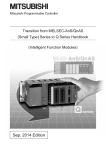
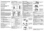
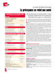
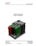
PERIPHERALS
The following figure shows the peripherals when the RD75 is used.
Positioning module
Drive unit
Manual pulse generator
Machine system inputs (switches)
• Near-point dog
• Limit switch
• External command signal
• Stop signal
13
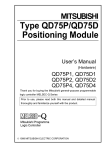
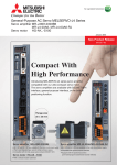
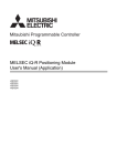
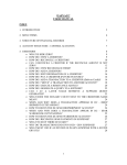
1
PART NAMES
This chapter describes the part names of the RD75.
RD75P2
(1)
RD75P4
RD75D2
(2)
(1)
(2)
(2)
(1)
(2)
(3)
(3)
(3)
(3)
(3)
(3)
(4)
(4)
(4)
(1)
RD75D4
(5)
(5)
(5)
(4)
(5)
No.
Name
Description
(1)
RUN LED
For details, refer to the following.
Page 14 LED Display Specifications
(2)
ERR LED
(3)
Axis display LED (AX1 to AX4)
(4)
Connectors for external devices
Connects to a drive unit, mechanical system input, or manual pulse generator.
For the signal layout, refer to the following.
Page 44 Signal layouts of connectors for external devices
AX1: Axis 1, AX2: Axis 2, AX3: Axis 3, AX4: Axis 4
(5)
Production information marking
Shows the production information (16 digits) of the module.
1.1
LED Display Specifications
This section lists LED display specifications.
: Off, : On, ●: Flashing (at 400ms intervals)
RD75 status
LED display
Normal operation
RUN:
AX3:
AX4:
ERR:
AX1:
AX2:
RUN:
AX3:
AX4:
ERR:
AX1:
AX2:
The axis in operation
RUN:
AX3:
AX4:
ERR:
AX1: ●
AX2:
Minor error
RUN:
AX3:
AX4:
ERR: ●
AX1:
AX2:
Moderate error
RUN:
AX3:
AX4:
ERR:
AX1:
AX2:
RUN:
AX3:
AX4:
ERR:
AX1:
AX2:
RUN: ●
AX3:
AX4:
ERR:
AX1:
AX2:
When the target module is selected
RUN:
AX3:
AX4:
ERR:
AX1:
AX2:
When the target module is ready to be replaced
Operation failure
Online module change
14
1 PART NAMES
1.1 LED Display Specifications
Description
• The axes stopped
• The axes on standby
MEMO
1
1 PART NAMES
1.1 LED Display Specifications
15
2
SPECIFICATIONS
This chapter describes the performance specifications of the RD75.
2.1
Performance Specifications
This section lists the performance specifications of the RD75.
Item
RD75P2*1
RD75D2*1
RD75P4*1
RD75D4*1
Number of controlled axes
2 axes
4 axes
Interpolation function
2-axis linear interpolation
2-axis circular interpolation
2-, 3-, or 4-axis linear interpolation
2-axis circular interpolation
3-axis helical interpolation
Control method
PTP (Point To Point) control, path control (line, arc, and helix can be set), speed control, speed-position
switching control, position-speed switching control
Control unit
mm, inch, degree, pulse
Positioning data
600 data/axis
Module data backup function
Positioning data, and block start data can be saved on the flash ROM (battery-less backup)
Positioning
PTP control: Incremental system/absolute system
Positioning system
Speed-position switching control: Incremental system/absolute system
Position-speed switching control: Incremental system
Path control: Incremental system/absolute system
16
Positioning range
In absolute system
-214748364.8 to 214748364.7m
-21474.83648 to 21474.83647 inch
0 to 359.99999 degree
-2147483648 to 2147483647 pulse
In incremental system
-214748364.8 to 214748364.7m
-21474.83648 to 21474.83647 inch
-21474.83648 to 21474.83647 degree
-2147483648 to 2147483647 pulse
In speed-position switching control (INC mode)/position-speed switching control
0 to 214748364.7m
0 to 21474.83647 inches
0 to 21474.83647 degree
0 to 2147483647 pulses
In speed-position switching control (ABS mode)*2
0 to 359.99999 degree
Speed command
0.01 to 20000000.00mm/min
0.001 to 2000000.000inch/min
0.001 to 3000000.000 degree/min
1 to 5000000 pulse/s
Acceleration/deceleration
processing
Trapezoidal acceleration/deceleration, S-curve acceleration/deceleration
Acceleration/deceleration time
1 to 8388608ms (Four patterns can be set for each of acceleration time and deceleration time.)
Sudden stop deceleration time
1 to 8388608ms
2 SPECIFICATIONS
2.1 Performance Specifications
RD75P2*1
Item
*3
Start time
Quick start
function*4
RD75D2*1
1-axis linear control
0.3ms (1.5ms)
1-axis speed control
0.3ms (1.5ms)*8
2-axis linear interpolation
control (composite speed)
0.45ms (1.5ms)*8
2-axis linear interpolation
control (reference axis speed)
0.45ms (1.5ms)*8
2
0.63ms
2-axis speed control
0.63ms (1.5ms)*8
3-axis linear interpolation
control (composite speed)
0.93ms (1.7ms)*8
3-axis linear interpolation
control (reference axis speed)
0.93ms (1.7ms)*8
3-axis helical interpolation
control
1.8ms (2.6ms)*8
3-axis speed control
0.93ms (1.7ms)*8
4-axis linear control
1.08ms (1.8ms)*8
4-axis speed control
1.08ms (1.8ms)*8
Start with the positioning start
signal
8s
Start with the external
command signal
20s
Start time adjustment function*5
0.00 to 10000.00ms (0.01ms unit)
Start time when the inter-module
synchronization function is used*6
8s
External connections
40-pin connector
Applicable
wire size*7
When A6CON1 or A6CON4 is
used
0.088 to 0.3 (28 to 22 AWG) stranded wire
When A6CON2 is used
0.088 to 0.24 (28 to 24 AWG) stranded wire
External wiring connector
A6CON1, A6CON2, A6CON4 (sold separately)
Maximum output pulse
200000 pulse/s
Manual pulse generator input maximum
frequency
1000 pulse/s
Manual pulse generator 1 pulse input
magnification
1 to 10000 times
Maximum connection distance between
servos
2m
Number of write accesses to a flash ROM
100000 times maximum
5000000 pulse/s
200000 pulse/s
5000000 pulse/s
10m
2m
10m
0.54A
0.42A
0.78A
0.15kg
0.15kg
0.15kg
Number of occupied I/O points
32 points (I/O assignment: Intelligent 32 points)
Internal current consumption (5VDC)
0.38A
External
dimensions
106mm
Weight
*1
*2
*3
*4
*5
*6
*7
*8
RD75D4*1
(2.0ms)*8
2-axis circular interpolation
control
Height
RD75P4*1
*8
Width
27.8mm
Depth
110mm
0.14kg
The RD75P2 and RD75P4 are modules of transistor output system, and the RD75D2 and RD75D4 are modules of differential driver
output system.
The speed-position switching control (ABS mode) can be used only when the control unit is degree.
Analysis time of positioning data varies depending on the operating status of the partner axis. The start time and operation timing
described in this manual are for the case when all axes stop the operation.
The start time of the quick start function indicates the period from the acceptance of the start trigger (positioning start signal, external
command signal) to the start of pulse output, after the positioning data analysis is completed.
The function can be set only when the quick start function is used.
The start time of when the inter-module synchronization function is used is the period from the acceptance of the start trigger (start of
inter-module synchronization cycle) to the start of pulse output, after the positioning data analysis is completed.
Use cables with outside diameter of 1.3mm or shorter to connect 40 cables to the connector. In addition, consider the amount of current
to be used and select appropriate cables.
The value in parentheses indicates the start time of when Q compatible mode is set.
For Q compatible mode, refer to the following.
MELSEC iQ-R Positioning Module User's Manual (Application)
2 SPECIFICATIONS
2.1 Performance Specifications
17
2.2
Specifications of Input/output Interfaces with
External Devices
Electrical specifications of I/O signals
Input specifications
Signal name
Rated input
voltage/
current
Operating
voltage range
ON voltage/
current
OFF voltage/
current
Input
resistance
Response
time
Drive unit READY signal (READY)
Stop signal (STOP)
Upper limit signal (FLS)
Lower limit signal (RLS)
24VDC/5mA
19.2 to 26.4VDC
17.5VDC or
higher/3.5mA or
higher
7VDC or lower/
1.7mA or lower
Approx. 4.7k
4ms or less
Zero signal (PG05/PG024)
5VDC/5mA
4.5 to 6.1VDC
2VDC or higher/
2mA or higher
0.5VDC or lower/
0.5mA or lower
Approx. 620
1ms or less
24VDC/5mA
12 to 26.4VDC
10VDC or higher/
3mA or higher
3VDC or lower/
0.2mA or lower
Approx. 4.7k
1ms or less
ON
3μs or
less
3μs or less
1ms or more
OFF
Differential receiver equivalent to AM26LS32 (ON/OFF level ON: 1.8V or higher, OFF: 0.6V or lower)
Manual pulse generator connection
Manual pulse generator A phase
(PULSER A)
Manual pulse generator B phase
(PULSER B)
5VDC/5mA
4.5 to 6.1VDC
2.5VDC or higher/
2mA or higher
1VDC or lower/
0.1mA or lower
Approx. 1.1k
1ms or less
Pulse width (duty ratio: 50%)
4ms or more
2ms
or more
2ms
or more
Phase difference (When the A phase leads the B phase, the positioning address (current value) increases.)
A phase
B phase
1ms or more
Near-point dog signal (DOG)
24VDC/5mA
19.2 to 26.4VDC
17.5VDC or
higher/3.5mA or
higher
7VDC or lower/
1.7mA or lower
Approx. 4.3k
1ms or less
External command signal (CHG)
24VDC/5mA
19.2 to 26.4VDC
19VDC or higher/
2.7mA or higher
7VDC or lower/
0.8mA or lower
Approx. 7.7k
20s
Signal name
Rated load
voltage
Operating
load voltage
range
Maximum load
current/inrush
current
Maximum
voltage drop at
ON
Leakage
current at
OFF
Response
time
Deviation counter clear signal
(CLEAR)
5 to 24VDC
4.75 to 30VDC
0.1A/1 point/0.4A
10ms or less
1VDC (TYP)
2.5VDC (MAX)
0.1mA or lower
2ms or less
(resistive load)
RD75P
Pulse output (PULSE F)
Pulse output (PULSE R)
5 to 24VDC
4.75 to 30VDC
50mA/1 point/
200mA 10ms or
less
0.5VDC (TYP)
0.1mA or lower
RD75D
Pulse output F (+) (PULSE F+/-)
Pulse output R (+) (PULSE R+/-)
Differential driver equivalent to AM26C31
Output specifications
18
2 SPECIFICATIONS
2.2 Specifications of Input/output Interfaces with External Devices
■The relation of pulse output with [Pr.5] Pulse output mode and [Pr.23] Output signal logic
selection
Pulse output mode (PULSE/SIGN, CW/CCW, A phase/B phase) can be selected in [Pr.5] Pulse output mode according to the
drive unit specifications.
The logic of output signals (positive logic, negative logic) is selected in [Pr.23] Output signal logic selection as well.
2
The relation of pulse output with [Pr.5] Pulse output mode and [Pr.23] Output signal logic selection is shown below.
• RD75P
The voltage of terminals having the PULSE COM terminal as a reference is shown. ( Page 48 Internal circuit of input/
output interface)
(High OFF, Low ON)
"[Pr.5] Pulse
output mode"
Terminal
name
"[Pr.23] Output signal logic selection"
Positive logic
Forward run
PULSE/SIGN
PULSE F
PULSE R
A phase/
B phase
Reverse run
Forward run
Reverse run
PULSE F
PULSE R
CW/CCW
Negative logic
PULSE F
PULSE R
High
Low
High
Low
High
Low
High
Low
High
Low
High
Low
High
Low
High
Low
High
Low
High
Low
High
Low
High
Low
2 SPECIFICATIONS
2.2 Specifications of Input/output Interfaces with External Devices
19
• RD75D
The voltage of terminals having the differential driver common terminal as a reference is shown. ( Page 48 Internal circuit
of input/output interface)
"[Pr.5] Pulse
output mode"
Terminal
name
"[Pr.23] Output signal logic selection"
Positive logic
Forward run
Negative logic
Reverse run
Forward run
PULSE/SIGN
PULSE F+
PULSE F-
PULSE R+
PULSE R-
High
Low
High
Low
High
Low
High
Low
High
Low
High
Low
High
Low
High
Low
High
Low
High
Low
High
Low
High
Low
High
Low
High
Low
High
Low
High
Low
High
Low
High
Low
High
Low
High
Low
High
Low
High
Low
High
Low
High
Low
CW/CCW
PULSE F+
PULSE F-
PULSE R+
PULSE R-
A phase/
B phase
PULSE F+
PULSE F-
PULSE R+
PULSE R-
20
2 SPECIFICATIONS
2.2 Specifications of Input/output Interfaces with External Devices
Reverse run
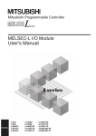
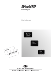
■ [Pr.5] Pulse output mode and [Pr.23] Output signal logic selection
Set [Pr.5] Pulse output mode and [Pr.23] Output signal logic selection according to the specifications of a connected servo
amplifier.
If not, the motor may rotate in the reverse direction or may not rotate at all.
Connection examples with a MELSERVO-J4 series servo amplifier are shown below.
2
• RD75P
[Pr.5] Pulse
output mode
RD75P
([Pr.23] Output
signal logic
selection)
Logic of servo
amplifier, MR-J4-A
CW/CCW
Negative logic
Negative logic
Positive logic
Positive logic
PULSE/SIGN
A phase/B
phase
Negative logic
Negative logic
Positive logic
Positive logic
Negative logic
Negative logic
Negative logic
Positive logic
Positive logic
Negative logic
Positive logic
Positive logic
Connection example
MR-J4-A
servo amplifier
24VDC
OPC
RD75P
DOCOM
PULSE F
PP
PULSE COM
PULSE R
PULSE COM
NP
SD
• RD75D
[Pr.5] Pulse
output mode
RD75P
([Pr.23] Output
signal logic
selection)
CW/CCW
Negative logic
Positive logic
Positive logic
Negative logic
Negative logic
Positive logic
Positive logic
Negative logic
PULSE F+
PP
Negative logic
Negative logic
PULSE F-
PG
Negative logic
Positive logic
Positive logic
Negative logic
PULSE R+
NP
Positive logic
Positive logic
PULSE R-
NG
PULSE/SIGN
A phase/B
phase
Logic of servo
amplifier, MR-J4-A
Connection example
RD75D
MR-J4-A
servo amplifier
SD
2 SPECIFICATIONS
2.2 Specifications of Input/output Interfaces with External Devices
21
3
LIST OF FUNCTIONS
3.1
Control Function
Several functions are provided for the RD75. For details on each function, refer to the following.
MELSEC iQ-R Positioning Module User's Manual (Application)
In this manual and MELSEC iQ-R Positioning Module User's Manual (Application), the functions of the RD75 are
classified as follows to explain the positioning module.
Positioning function
This function starts the positioning operation to a specified position by using the positioning data, block start data, and
condition data.
Main functions
■OPR control
The OPR control function establishes a start point for performing the positioning control, and performs positioning toward that
start point. This function is used to return a workpiece, located at a position other than the OP when the power is turned on or
after the positioning stops, to the OP. The OPR control is preregistered in the RD75 as Positioning start data No.9001
(Machine OPR) or Positioning start data No.9002 (Fast OPR).
■Major positioning control
This control is performed using the positioning data stored in the RD75. The positioning controls, such as the position control
and speed control, are executed by setting the required items in this Positioning data and starting that positioning data.
Operation pattern can be set in this Positioning data, and with this whether to perform the control with continuous positioning
data (ex.: positioning data No.1, No.2, No.3, ...) can be set.
■Advanced positioning control
This control executes the positioning data stored in the RD75 by using Block start data. The following types of applied
positioning control can be performed.
• Random blocks, handling several continuing positioning data items as blocks, can be executed in the specified order.
• Condition judgment can be added to the position control and speed control.
• The operation of the positioning data that is set for multiple axes can be started simultaneously. (Pulses are output
simultaneously to multiple servos.)
• The specified positioning data can be executed repeatedly.
■Manual control
By inputting a signal into the RD75 from an external source, the RD75 will output a random pulse train and perform control
operations. Use this manual control to move the workpiece to a random position (JOG operation), and to finely adjust the
positioning (including the inching operation, and manual pulse generator operation).
Sub function
When the main functions are executed, this function compensates and limits controls, or adds functions.
Common functions
These function perform common controls for when the RD75 is used, such as Module data initialization function and Module
data backup function.
22
3 LIST OF FUNCTIONS
3.1 Control Function
3.2
Positioning Function
The following table lists the start modes for the positioning function.
Positioning start mode
Description
Normal start
Starts positioning controls by the simplest procedure. Major positioning controls and advanced positioning controls can be
started in this mode.
Quick start
Analyzes in advance the positioning data executed immediately after the current operation to quickly start the positioning
control. Major positioning controls can be started in this mode.
Multiple axes simultaneous start
Starts the operation of multiple axes simultaneously according to the pulse output level.
3.3
3
Main Functions
The following table shows the overview of the main functions for positioning controls with the RD75.
Main functions
OPR control
Major positioning
control
Description
Machine OPR control
Mechanically establishes the positioning start point using a near-point dog or stopper.
In the data setting method, no axis movement occurs since the current position is set
as OP.
(Positioning start No.9001)
Fast OPR control
Positions a target to the OP address ([Md.21] Machine feed value) stored in the
RD75 using OPR control. (Positioning start No.9002)
Position control
Speed control
Linear control
(1-axis linear control)
(2-axis linear
interpolation control)
(3-axis linear
interpolation control)
(4-axis linear
interpolation control)
Positions a target using a linear path to the address set in the positioning data or to
the position specified with the movement amount.
Fixed-feed control
(1-axis fixed-feed
control)
(2-axis fixed-feed
control)
(3-axis fixed-feed
control)
(4-axis fixed-feed
control)
Positions a target by the movement amount specified with the amount set in the
positioning data.
(With the fixed-feed control, [Md.20] Current feed value is set to 0 when the control is
started. In the 2-axis fixed-feed control, 3-axis fixed-feed control, or 4-axis fixed-feed
control, the fixed-feed is performed along a linear path obtained by interpolation.)
2-axis circular
interpolation control
Positions a target using an arc path to the address set in the positioning data, or to
the position specified with the movement amount, sub point, or center point.
3-axis helical
interpolation control
Positions a target using a helical path to a specified position. (Specify the position by
specifying the end point address directly or by specifying the relative distance from
the current position (movement amount).)
Speed control
(1-axis speed control)
(2-axis speed control)
(3-axis speed control)
(4-axis speed control)
Continuously outputs the pulses corresponding to the command speed set in the
positioning data.
Speed-position switching control
Performs the speed control, and position control (Positioning with the specified
address or movement amount) immediately after that by turning on Speed-position
switching signal.
Position-speed switching control
Performs the position control, and speed control (Continuous output of the pulses
corresponding to the specified command speed) immediately after that by turning on
Position-speed switching signal.
3 LIST OF FUNCTIONS
3.2 Positioning Function
23
Main functions
Major positioning
control
Advanced
positioning control
Manual control
Description
Other controls
Current value change
Changes [Md.20] Current feed value to the address set in the positioning data.
The following two methods can be used.
(Machine feed value cannot be changed.)
• Current value change using positioning data
• Current value change using the start No. for a current value change (No.9003)
NOP instruction
A control method that is not executed. When the NOP instruction is set, the operation
of the next data starts and this instruction is not executed.
JUMP instruction
Unconditionally or conditionally jumps to the specified positioning data No.
LOOP
Performs the loop control with repeated LOOP to LEND.
LEND
Returns to the beginning of the loop control with repeated LOOP to LEND.
Block start
(Normal start)
With one start, executes the positioning data in a random block with the set order.
Condition start
Judges the condition set in Condition data for the specified positioning data, and
executes Block start data.
When the condition is established, Block start data is executed.
When not established, that block start data is ignored, and the next point's block start
data is executed.
Wait start
Judges the condition set in Condition data for the specified positioning data, and
executes Block start data.
When the condition is established, Block start data is executed. When not
established, the control stops (waits) until the condition is established.
Simultaneous start
Simultaneously executes the positioning data having the number for the axis
specified with Condition data (Outputs pulses at the same timing).
Repeated start
(FOR loop)
Repeats the program from the block start data set with FOR loop to the block start
data set in NEXT for the specified number of times.
Repeated start
(FOR condition)
Repeats the program from the block start data set with FOR condition to the block
start data set in NEXT until the conditions set in Condition data are established.
JOG operation
Outputs pulses to the drive unit while JOG start signal is on.
Inching operation
Outputs pulses corresponding to a minute movement amount by the manual
operation to the drive unit.
(Performs the fine adjustment with JOG start signal.)
Manual pulse generator operation
Outputs pulses commanded with the manual pulse generator to the drive unit.
(Performs the fine adjustment and others at the pulse level.)
Inter-module synchronization function (simultaneous start of multiple
modules)
Starts pulse output at the same timing of inter-module synchronization cycle after the
acceptance of a positioning start trigger.
With Major positioning control (Advanced positioning control), whether or not to continuously execute the positioning data can
be set with Operation pattern. The following shows the overview of Operation pattern.
24
[Da.1] Operation pattern
Description
Independent positioning control
(Positioning complete)
When Independent positioning control is set for the operation pattern of the started positioning data, only the specified
positioning data will be executed, and the positioning will end.
Continuous positioning control
When Continuous positioning control is set for the operation pattern of the started positioning data, after the specified
positioning data is executed, the program will stop once, and the next following positioning data will be executed.
Continuous path control
When Continuous path control is set for the operation pattern of the started positioning data, the specified positioning
data will be executed, and the next following positioning data will be executed without deceleration stop.
3 LIST OF FUNCTIONS
3.3 Main Functions
3.4
Sub Functions and Common Functions
Sub function
The following table shows the overview of the functions that assist positioning controls using the RD75.
Sub function
Sub functions specific to
machine OPR
Function to compensate
control
Function to limit control
Functions that change
control details
Function related to
positioning start
Description
OPR retry function
OP shift function
After the machine OPR, this function compensates the position by the specified distance from
the machine OP position and sets that position as the OP address.
Backlash compensation function
Compensates the backlash amount of the machine system. Feed pulses equivalent to the set
backlash amount are output each time the movement direction changes.
Electronic gear function
By setting the movement amount per pulse, this function can freely change the machine
movement amount per commanded pulse.
A flexible positioning system that matches the machine system can be structured with this
function.
Near pass function*1
Suppresses the machine vibration when the speed change is performed during the continuous
path control in the interpolation control.
Output timing selection of near
pass control
This function allows the user to select the timing to output the difference (d) between the
actual and the set positioning end addresses in the continuous path control, in which the
difference (d) is output during the execution of the next positioning data.
Speed limit function
If the command speed exceeds [Pr.8] Speed limit value during the control, this function limits
the command speed to within the setting range of [Pr.8] Speed limit value.
Torque limit function*2
If the torque generated in the servo motor exceeds [Pr.17] Torque limit setting value during the
control, this function limits the generated torque to within the setting range of [Pr.17] Torque
limit setting value.
Software stroke limit function
If a command outside of the upper/lower limit stroke limit setting range, set in the parameters,
is issued, this function will not execute the positioning for that command.
Hardware stroke limit function
Performs the deceleration stop with the limit switch connected to the RD75's connector for
external devices.
Speed change function
Changes the speed during positioning.
Set the new speed in [Cd.14] New speed value, the speed change buffer memory area, and
change the speed with [Cd.15] Speed change request.
Override function
Changes the speed during positioning within a percentage of 0 to 300%. Execute this function
using [Cd.13] Positioning operation speed override.
Acceleration/deceleration time
change function
Changes the acceleration/deceleration time at the speed change.
Torque change function
Changes Torque limit value during the control.
Target position change function
Changes the target position during positioning.
The position and speed can be changed simultaneously.
Pre-reading start function
If the positioning start is requested while Execution prohibition flag is on, no pulse is output,
and when Execution prohibition flag is turned off and detected, outputting pulses is started
within 0.88ms.
Start time adjustment function
After the start trigger was input with the quick start function, this function starts outputting
pulses after the preset time has passed.
Absolute position restoration function*3
*1
*2
*3
Retries the machine OPR with the upper/lower limit switches during the machine OPR. This
allows the machine OPR to be performed even if the axis is not returned to a position before
the near-point dog with operations such as the JOG operation.
3
Restores the absolute position of a specified axis.
The near pass function is featured as standard, and is valid only during the position control. The function cannot be set to be invalid with
parameters.
To perform Torque limit, a D/A converter module and a drive unit capable of the torque limit command with an analog voltage must be
needed.
An I/O module with arbitrary number of points and a drive unit capable of configuring an absolute position detection system (which is a
Mitsubishi General-Purpose AC Servo and has an absolute position detection function (absolute position data transfer protocol)
equivalent to that of MR-J3-A) are needed.
3 LIST OF FUNCTIONS
3.4 Sub Functions and Common Functions
25
Sub function
Function related to
positioning stop
Other functions
Description
Stop command processing for
deceleration stop function
Selects a deceleration curve when a stop cause occurs during the deceleration stop
processing to speed 0.
Continuous operation interrupt
function
Interrupts the continuous operation. When this request is accepted, the operation will stop at
the completion of the positioning data being executed.
Step function
Temporarily stops the operation to check the positioning operation during debugging and
other operation. The operation can be stopped for each Automatic deceleration or Positioning
data.
Skip function
Pauses (decelerates to stop) the positioning being executed when Skip signal is input, and
performs the next positioning.
M code output function
Issues a command for a subsidiary work (such as stopping clamps or drills and changing
tools) corresponding to each M code number (0 to 65535) that can be set to each positioning
data.
Teaching function
Stores the address positioned with the manual control into the positioning address of the
specified positioning data No. ([Cd.39]).
Command in-position function
Calculates the remaining distance for the RD75 to reach the positioning stop position, and
sets Command in-position flag to 1 when the value is less than the set value.
When performing another subsidiary work before the control ends, use this function as a
trigger for the subsidiary work.
Acceleration/deceleration
processing function
Adjusts acceleration/deceleration of the control.
Deceleration start flag function
To inform the stop timing, this function turns on Deceleration start flag when the speed status
is changed from the constant speed or acceleration to deceleration during the position control
whose operation pattern is Positioning complete.
During uncompleted OPR
operation setting function
Sets whether or not to execute the positioning control when OPR request flag is on.
Interrupt function
Generates an interrupt request to the CPU module when an interrupt factor is detected, and
starts an interrupt program.
Common functions
The following table shows the overview of the functions executed as necessary.
26
Common functions
Description
Module data initialization function
Returns the setting data stored in the RD75 buffer memory and flash ROM to the initial values set at the factory.
Module data backup function
Writes the positioning data and block start data, currently being used for control, to the flash ROM.
External I/O signal logic switching
function
Switches I/O signal logics according to the equipment connected to the RD75. For the system in which signals
handled as normally closed contacts (such as Drive unit READY signal and limit signals) are not used, the parameter
logic setting can be controlled without wiring if the setting is changed to Positive logic.
External I/O signal monitor function
Monitors External I/O signal using the module's detailed information which can be displayed on the system monitor of
an engineering tool.
History monitor function
Monitors the error history, warning history, and start history of all axes.
Online module change
Allows module replacement without stopping the system. For the procedure of the online module change, refer to the
following.
MELSEC iQ-R Online Module Change Manual
3 LIST OF FUNCTIONS
3.4 Sub Functions and Common Functions
3.5
Combination of Main and Sub Functions
With positioning control using the RD75, the main functions and sub functions can be combined and used as necessary.
: Always combined, : Combination possible, : Combination limited, : Combination not possible
Main functions
Combination with
operation pattern*1
Function specific to
machine OPR
Function to compensate
control
OPR retry
function
OP shift
function
Backlash
compensation
function
Electronic
gear function
OPR
control
Machine OPR control
Fast OPR control
Major
positioning
control
Position
control
1-axis linear control
2-/3-/4-axis linear
interpolation control
1-axis fixed-feed control
(Continuous path control
cannot be set)
2-/3-/4-axis fixed-feed
control (Interpolation)
(Continuous path control
cannot be set)
2-axis circular
interpolation control
3-axis helical interpolation
control
Speed control (1- to 4-axis)
(Only independent
positioning control can be
set)
Speed-position switching control
Position-speed switching control
(Only independent
positioning control can be
set)
Other
controls
Current value change
(Continuous path control
cannot be set)
NOP instruction
JUMP instruction
JOG operation, Inching operation
Manual pulse generator operation
LOOP to LEND
Manual
control
*1
3
The operation pattern is one of the setting items for Positioning data.
3 LIST OF FUNCTIONS
3.5 Combination of Main and Sub Functions
27
Main functions
OPR
control
Major
positioning
control
Manual
control
*2
*3
*4
28
Function to
compensate control
Function to limit control
Near
pass
function
Output
timing
selection of
near pass
control
Speed
limit
function
Torque
limit
function
Software
stroke limit
function
Hardware
stroke limit
function
Speed
change
function
*2
*3
Fast OPR control
Position
control
1-axis linear control
2-/3-/4-axis linear
interpolation control
1-axis fixed-feed control
2-/3-/4-axis fixed-feed
control (Interpolation)
2-axis circular
interpolation control
3-axis helical
interpolation control
Speed control (1- to 4-axis)
Speed-position switching control
Position-speed switching control
Other
controls
Current value change
NOP instruction
JUMP instruction
LOOP to LEND
JOG operation, Inching operation
*4
Manual pulse generator operation
Machine OPR control
Functions
that
change
control
details
The near pass function is featured as standard. The function is valid only when the continuous path control for position control
operations is set.
Invalid during creep speed.
Combination with the inching operation is not available. (The inching operation does not perform acceleration/deceleration processing.)
3 LIST OF FUNCTIONS
3.5 Combination of Main and Sub Functions
Main functions
Functions that change control details
Function related to positioning start
Override
function
Acceleration/
deceleration
time change
function
Torque
change
function
Target
position
change
function
Restart
function
Prereading
start
function
Start time
adjustment
function
*5
*5
OPR control
Machine OPR control
Fast OPR control
Major
positioning
control
Position
control
1-axis linear control
*7
2-/3-/4-axis linear
interpolation control
1-axis fixed-feed
control
2-/3-/4-axis fixed-feed
control (Interpolation)
2-axis circular
interpolation control
3-axis helical
interpolation control
Speed control (1- to 4-axis)
Speed-position switching control
Position-speed switching control
Other
controls
Current value change
NOP instruction
JUMP instruction
LOOP to LEND
JOG operation, Inching operation
*6
*6
Manual pulse generator operation
Manual
control
*5
*6
*7
3
Invalid during creep speed.
Combination with the inching operation is not available. (The inching operation does not perform acceleration/deceleration processing.)
Invalid while the continuous path control is in operation.
3 LIST OF FUNCTIONS
3.5 Combination of Main and Sub Functions
29
Main functions
Other functions
Step
function
Stop command
processing for
deceleration stop
function
Continuous
operation
interrupt
function
Stop
processing
function
Skip
function
M code
output
function
OPR
control
Machine OPR control
Fast OPR control
Major
positioning
control
Position
control
1-axis linear control
2-/3-/4-axis linear
interpolation control
1-axis fixed-feed
control
2-/3-/4-axis fixedfeed control
(Interpolation)
2-axis circular
interpolation control
3-axis helical
interpolation control
Speed control (1- to 4-axis)
Speed-position switching control
Position-speed switching control
Other
controls
Current value
change
*9
NOP instruction
JUMP instruction
LOOP to LEND
JOG operation, Inching operation
*8
Manual pulse generator operation
Manual
control
*8
*9
30
Function related to positioning stop
Combination with the inching operation is not available. (The inching operation does not perform acceleration/deceleration processing.)
Use the function for the current value change using positioning data. The function is not available for the current value change using the
start No. for a current value change (No.9003).
3 LIST OF FUNCTIONS
3.5 Combination of Main and Sub Functions
Main functions
OPR
control
Major
positioning
control
Other functions
*10
*11
*12
*13
Command
in-position
function
Acceleration/
deceleration
processing
function
Deceleration
start flag
function
During
uncompleted
OPR
operation
setting
function
Interrupt
function*13
Machine OPR control
Fast OPR control
Position
control
1-axis linear control
2-/3-/4-axis linear
interpolation control
*11
1-axis fixed-feed
control
2-/3-/4-axis fixed-feed
control (Interpolation)
*11
2-axis circular
interpolation control
3-axis helical
interpolation control
Speed control (1- to 4-axis)
Manual
control
Teaching
function
*12
Speed-position switching control
Position-speed switching control
*12
Other
controls
Current value change
NOP instruction
JUMP instruction
LOOP to LEND
JOG operation, Inching operation
Manual pulse generator operation
*10
3
Combination with the inching operation is not available. (The inching operation does not perform acceleration/deceleration processing.)
Valid for the reference axis only.
Valid for only in the case where the deceleration start is made during position control.
No limitation for combination use with other functions. Satisfaction judgment of interruption conditions is performed as needed.
3 LIST OF FUNCTIONS
3.5 Combination of Main and Sub Functions
31
3.6
Combination Among Sub Functions
The following shows the combinations of sub-functions and sub-functions during the control of the main functions.
: Combination possible, : Combination limited, : Combination not possible
Function name
OPR retry
function
OP shift
function
Backlash
compensation
function
Electronic
gear function
Near pass
function
Function specific
to machine OPR
OPR retry function
OP shift function
Function to
compensate
control
Backlash compensation
function
Electronic gear function
Near pass function
Output timing selection of near
pass control
Speed limit function
Torque limit function
Software stroke limit function
Hardware stroke limit function
Speed change function
*1
*1
Override function
*1
*1
Acceleration/deceleration time
change function
Torque change function
Target position change function
Start time adjustment function
Restart function
Pre-reading start function
Absolute position restoration function
Function related
to positioning
stop
Step function
Stop command processing for
deceleration stop function
Continuous operation interrupt
function
Function to limit
control
Functions that
change control
details
Function related
to positioning
start
Other functions
*1
*2
32
Sub function to be combined
Stop processing function
Skip function
M code output function
Teaching function
Command in-position function
Acceleration/deceleration
processing function
Deceleration start flag function
During uncompleted OPR
operation setting function
Interrupt function*2
Speed cannot be changed to zero.
No limitation for combination use with other functions. Satisfaction judgment of interruption conditions is performed as needed.
3 LIST OF FUNCTIONS
3.6 Combination Among Sub Functions
Function name
Sub function to be combined
Output timing
selection of
near pass
control
Speed limit
function
Torque limit
function
Software stroke
limit function
Hardware stroke
limit function
Function specific
to machine OPR
OPR retry function
OP shift function
Function to
compensate
control
Backlash compensation
function
Electronic gear function
Near pass function
Output timing selection of near
pass control
Speed limit function
Torque limit function
Software stroke limit function
Hardware stroke limit function
Speed change function
Override function
Acceleration/deceleration time
change function
Torque change function
Target position change function
Start time adjustment function
Restart function
Pre-reading start function
Absolute position restoration function
Function related
to positioning
stop
Step function
Stop command processing for
deceleration stop function
Continuous operation interrupt
function
Function to limit
control
Functions that
change control
details
Function related
to positioning
start
Other functions
*3
Stop processing function
Skip function
M code output function
Teaching function
Command in-position function
Acceleration/deceleration
processing function
Deceleration start flag function
During uncompleted OPR
operation setting function
Interrupt function*3
3
No limitation for combination use with other functions. Satisfaction judgment of interruption conditions is performed as needed.
3 LIST OF FUNCTIONS
3.6 Combination Among Sub Functions
33
Function name
Speed change
function
Override
function
Acceleration/
deceleration
time change
function
Torque change
function
Target position
change
function
OPR retry function
*4
*4
OP shift function
*4
*4
Backlash compensation
function
Electronic gear function
Near pass function
Output timing selection of near
pass control
Speed limit function
Torque limit function
Software stroke limit function
Hardware stroke limit function
Speed change function
Override function
Acceleration/deceleration time
change function
Torque change function
Target position change function
Start time adjustment function
Restart function
Pre-reading start function
Absolute position restoration function
Function related
to positioning
stop
Step function
Stop command processing for
deceleration stop function
Continuous operation interrupt
function
Function specific
to machine OPR
Function to
compensate
control
Function to limit
control
Functions that
change control
details
Function related
to positioning
start
Other functions
*4
*5
*6
*7
34
Sub function to be combined
Stop processing function
Skip function
*5
M code output function
Teaching function
Command in-position function
Acceleration/deceleration
processing function
Deceleration start flag function
*6
*6
During uncompleted OPR
operation setting function
Interrupt function*7
Speed cannot be changed to zero.
For the control using External command signal, only one of the functions can be used.
Deceleration start flag does not turn on when the speed change function or override function is used to make deceleration.
No limitation for combination use with other functions. Satisfaction judgment of interruption conditions is performed as needed.
3 LIST OF FUNCTIONS
3.6 Combination Among Sub Functions
Function name
Sub function to be combined
Start time
adjustment
function
Restart
function
Pre-reading
start function
Absolute
position
restoration
function
Step function
Function specific
to machine OPR
OPR retry function
OP shift function
Function to
compensate
control
Backlash compensation
function
Electronic gear function
Near pass function
Output timing selection of near
pass control
Speed limit function
Torque limit function
Software stroke limit function
Hardware stroke limit function
Speed change function
Override function
Acceleration/deceleration time
change function
Torque change function
Target position change function
Start time adjustment function
Restart function
Pre-reading start function
Absolute position restoration function
Function related
to positioning
stop
Step function
Stop command processing for
deceleration stop function
Continuous operation interrupt
function
Function to limit
control
Functions that
change control
details
Function related
to positioning
start
Other functions
*8
Stop processing function
Skip function
M code output function
Teaching function
Command in-position function
Acceleration/deceleration
processing function
Deceleration start flag function
During uncompleted OPR
operation setting function
Interrupt function*8
3
No limitation for combination use with other functions. Satisfaction judgment of interruption conditions is performed as needed.
3 LIST OF FUNCTIONS
3.6 Combination Among Sub Functions
35
Function name
Sub function to be combined
Stop
command
processing for
deceleration
stop function
Continuous
operation
interrupt
function
Stop
processing
function
Skip function
M code output
function
Function specific
to machine OPR
OPR retry function
OP shift function
Function to
compensate
control
Backlash compensation
function
Electronic gear function
Near pass function
Output timing selection of near
pass control
Speed limit function
Torque limit function
Software stroke limit function
Hardware stroke limit function
Function to limit
control
Functions that
change control
details
Function related
to positioning
start
Speed change function
*9
Override function
Acceleration/deceleration time
change function
Torque change function
Target position change function
Start time adjustment function
Restart function
Pre-reading start function
Absolute position restoration function
Function related
to positioning
stop
Step function
Stop command processing for
deceleration stop function
Continuous operation interrupt
function
Other functions
Stop processing function
Skip function
*10
M code output function
*10
Teaching function
Command in-position function
Acceleration/deceleration
processing function
Deceleration start flag function
During uncompleted OPR
operation setting function
Interrupt function*11
*9 For the control using External command signal, only one of the functions can be used.
*10 M code ON signals [X4, X5, X6, X7] do not turn on when the M code output is set to the AFTER mode (When 1: AFTER mode is set in
[Pr.18] M code ON signal output timing).
*11 No limitation for combination use with other functions. Satisfaction judgment of interruption conditions is performed as needed.
36
3 LIST OF FUNCTIONS
3.6 Combination Among Sub Functions
Function name
Sub function to be combined
Teaching
function
Command
in-position
function
Acceleration/
deceleration
processing
function
Deceleration
start flag
During
uncompleted
OPR
operation
setting
function
Interrupt
function
Function specific
to machine OPR
OPR retry function
OP shift function
Function to
compensate
control
Backlash compensation
function
Electronic gear function
Near pass function
Output timing selection of near
pass control
Speed limit function
Torque limit function
Software stroke limit function
Hardware stroke limit function
Speed change function
*12
Override function
*12
Acceleration/deceleration time
change function
Torque change function
Target position change function
Start time adjustment function
Restart function
Pre-reading start function
Function to limit
control
Functions that
change control
details
Function related
to positioning
start
Absolute position restoration function
Function related
to positioning
stop
Step function
Stop command processing for
deceleration stop function
Continuous operation interrupt
function
Stop processing function
Skip function
M code output function
Teaching function
Command in-position function
Acceleration/deceleration
processing function
Deceleration start flag function
During uncompleted OPR
operation setting function
Interrupt function*13
Other functions
3
*12 Deceleration start flag does not turn on when the speed change function or override function is used to make deceleration.
*13 No limitation for combination use with other functions. Satisfaction judgment of interruption conditions is performed as needed.
3 LIST OF FUNCTIONS
3.6 Combination Among Sub Functions
37
4
PROCEDURES BEFORE OPERATIONS
This chapter describes the procedures before operation.
1.
Mounting the module
Mount the RD75 on the main base unit or extension base unit. For details, refer to the following.
MELSEC iQ-R Module Configuration Manual
2.
Wiring
Connect the RD75 to external devices.
3.
Adding the module
Add the RD75 to the module map of the project using an engineering tool.
4.
Module setting
Set values for the module setting using an engineering tool. For details, refer to the following.
MELSEC iQ-R Positioning Module User's Manual (Application)
5.
Auto refresh setting
Set values for the refresh settings using an engineering tool. For details, refer to the following.
MELSEC iQ-R Positioning Module User's Manual (Application)
6.
Checking connections
Check that the RD75 is connected to external devices correctly.
7.
Programming
Create programs. For details, refer to the following.
MELSEC iQ-R Positioning Module User's Manual (Application)
8.
Test operation
Check that the positioning is correctly carried out as designed.
38
4 PROCEDURES BEFORE OPERATIONS
MEMO
4
4 PROCEDURES BEFORE OPERATIONS
39
5
WIRING
This chapter describes the overall configuration of the system using the RD75, and lists the devices configuring the system.
5.1
Wiring Precautions
Check the terminal layouts and wire the RD75 correctly.
For the terminal layouts, refer to the following.
Page 44 Signal layouts of connectors for external devices
40
5 WIRING
5.1 Wiring Precautions
Connectors for external devices
Precautions
• Tighten the connector screws within the specified torque range.
Screw
Tightening torque range
Connector screw (M2.6)
0.20 to 0.29Nm
• Use copper wire with a temperature rating of 75 or higher for the connector.
• Use UL listed connectors if necessary for UL compliance.
• The positions of PULSE COM terminals differ between the QD75D and the RD75D. Therefore, if the same 40-pin
connectors for the QD75D are used for the RD75D, additional wiring to the 40-pin connectors (2B20 and 2B19 pins) is
required.
Applicable connectors
5
Connectors for external devices to be used for the RD75 are sold separately.
The following tables list the applicable connectors, and the reference product of a crimping tool.
■40-pin connectors
Type
Model
Applicable wire size
Soldering type connector (straight type)
A6CON1*1
0.088 to 0.3mm2 (28 to 22 AWG) (stranded wire)
Crimping type connector (straight type)
A6CON2
0.088 to 0.24mm2 (28 to 24 AWG) (stranded wire)
Soldering type connector (dual purpose (straight/
oblique) type)
A6CON4*1
0.088 to 0.3mm2 (28 to 22 AWG) (stranded wire)
*1
Use wire with a sheath outside diameter of 1.3mm or less when the 40 pins are used.
Select appropriate cables according to the current value used.
The A6CON3 (IDC type connector (straight type)) cannot be used.
■40-pin connector crimping tool
Type
Model
Contact
Crimping tool
FCN-363T-T005/H
FUJITSU COMPONENT LIMITED
For how to wire the connector and how to use the crimping tool, contact the manufacturer.
5 WIRING
5.1 Wiring Precautions
41
Wiring example when shielded cables are used
The following figure shows an example of the noise reduction measure when the connector (A6CON1) is used:
Connector
Connector (A6CON1)
To external devices
(for two drive units)
Shielded
cable
Drive
unit
To external device
To drive unit
Use the shortest possible length to
ground the 2¾ or more FG wire.
(The shield must be grounded on
the RD75 side.)
To RD75
The length between the connector and the shielded
cables should be the shortest possible.
■Example of shielded cable processing
The following figure shows an example of the noise reduction measure when the connector (A6CON1) is used:
Remove the coverings from all shielded cables and bind
the appeared shields with a conductive tape.
Coat the wire with
insulaing tape.
Solder the shield of any one of the
shielded cables to the FG wire.
42
5 WIRING
5.1 Wiring Precautions
■Assembling of the connector (A6CON1)
Wrap the coated parts
with a heat shrinkable
tube.
5
Wiring methods, and installation and removal procedures for the connectors
For the wiring methods, and installation and removal procedures, refer to the following.
MELSEC iQ-R Module Configuration Manual
5 WIRING
5.1 Wiring Precautions
43
5.2
Connector for External Devices
Signal layouts of connectors for external devices
This section lists signal layouts of RD75 connectors for external devices.
• RD75P
Pin layout (front view of the
module)
2B20
2B19
2B18
2B17
2B16
2B15
2B14
2B13
2B12
2B11
2B10
2B9
2B8
2B7
2B6
2B5
2B4
2B3
2B2
2B1
44
2A20
2A19
2A18
2A17
2A16
2A15
2A14
2A13
2A12
2A11
2A10
2A9
2A8
2A7
2A6
2A5
2A4
2A3
2A2
2A1
1B20
1B19
1B18
1B17
1B16
1B15
1B14
1B13
1B12
1B11
1B10
1B9
1B8
1B7
1B6
1B5
1B4
1B3
1B2
1B1
1A20
1A19
1A18
1A17
1A16
1A15
1A14
1A13
1A12
1A11
1A10
1A9
1A8
1A7
1A6
1A5
1A4
1A3
1A2
1A1
Axis 4 (AX4)
Axis 3 (AX3)
Axis 2 (AX2)
Axis 1 (AX1)
Pin No.
Signal
name
Pin No.
Signal
name
Pin No.
Signal
name
Pin No.
Signal
name
2B20
Empty
2A20
Empty
1B20
PULSER B-
1A20
PULSER B-
2B19
Empty
2A19
Empty
1B19
PULSER A-
1A19
PULSER A+
2B18
PULSE COM
2A18
PULSE COM
1B18
PULSE COM
1A18
PULSE COM
2B17
PULSE R
2A17
PULSE R
1B17
PULSE R
1A17
PULSE R
2B16
PULSE COM
2A16
PULSE COM
1B16
PULSE COM
1A16
PULSE COM
2B15
PULSE F
2A15
PULSE F
1B15
PULSE F
1A15
PULSE F
2B14
CLRCOM
2A14
CLRCOM
1B14
CLRCOM
1A14
CLRCOM
2B13
CLEAR
2A13
CLEAR
1B13
CLEAR
1A13
CLEAR
2B12
RDYCOM
2A12
RDYCOM
1B12
RDYCOM
1A12
RDYCOM
2B11
READY
2A11
READY
1B11
READY
1A11
READY
2B10
PG0COM
2A10
PG0COM
1B10
PG0COM
1A10
PG0COM
2B9
PG05
2A9
PG05
1B9
PG05
1A9
PG05
2B8
PG024
2A8
PG024
1B8
PG024
1A8
PG024
2B7
COM
2A7
COM
1B7
COM
1A7
COM
2B6
COM
2A6
COM
1B6
COM
1A6
COM
2B5
CHG
2A5
CHG
1B5
CHG
1A5
CHG
2B4
STOP
2A4
STOP
1B4
STOP
1A4
STOP
2B3
DOG
2A3
DOG
1B3
DOG
1A3
DOG
2B2
RLS
2A2
RLS
1B2
RLS
1A2
RLS
2B1
FLS
2A1
FLS
1B1
FLS
1A1
FLS
5 WIRING
5.2 Connector for External Devices
• RD75D
Pin layout (front view of the
module)
2B20
2B19
2B18
2B17
2B16
2B15
2B14
2B13
2B12
2B11
2B10
2B9
2B8
2B7
2B6
2B5
2B4
2B3
2B2
2B1
2A20
2A19
2A18
2A17
2A16
2A15
2A14
2A13
2A12
2A11
2A10
2A9
2A8
2A7
2A6
2A5
2A4
2A3
2A2
2A1
1B20
1B19
1B18
1B17
1B16
1B15
1B14
1B13
1B12
1B11
1B10
1B9
1B8
1B7
1B6
1B5
1B4
1B3
1B2
1B1
1A20
1A19
1A18
1A17
1A16
1A15
1A14
1A13
1A12
1A11
1A10
1A9
1A8
1A7
1A6
1A5
1A4
1A3
1A2
1A1
Axis 4 (AX4)
Axis 3 (AX3)
Axis 2 (AX2)
Axis 1 (AX1)
Pin No.
Signal
name
Pin No.
Signal
name
Pin No.
Signal
name
Pin No.
Signal
name
2B20
PULSE COM
2A20
Empty
1B20
PULSER B-
1A20
PULSER B+
2B19
PULSE COM
2A19
Empty
1B19
PULSER A-
1A19
PULSER A+
2B18
PULSE R-
2A18
PULSE R-
1B18
PULSE R-
1A18
PULSE R-
2B17
PULSE R+
2A17
PULSE R+
1B17
PULSE R+
1A17
PULSE R+
2B16
PULSE F-
2A16
PULSE F-
1B16
PULSE F-
1A16
PULSE F-
2B15
PULSE F+
2A15
PULSE F+
1B15
PULSE F+
1A15
PULSE F+
2B14
CLRCOM
2A14
CLRCOM
1B14
CLRCOM
1A14
CLRCOM
2B13
CLEAR
2A13
CLEAR
1B13
CLEAR
1A13
CLEAR
2B12
RDYCOM
2A12
RDYCOM
1B12
RDYCOM
1A12
RDYCOM
2B11
READY
2A11
READY
1B11
READY
1A11
READY
2B10
PG0COM
2A10
PG0COM
1B10
PG0COM
1A10
PG0COM
2B9
PG05
2A9
PG05
1B9
PG05
1A9
PG05
2B8
PG024
2A8
PG024
1B8
PG024
1A8
PG024
2B7
COM
2A7
COM
1B7
COM
1A7
COM
2B6
COM
2A6
COM
1B6
COM
1A6
COM
2B5
CHG
2A5
CHG
1B5
CHG
1A5
CHG
2B4
STOP
2A4
STOP
1B4
STOP
1A4
STOP
2B3
DOG
2A3
DOG
1B3
DOG
1A3
DOG
2B2
RLS
2A2
RLS
1B2
RLS
1A2
RLS
2B1
FLS
2A1
FLS
1B1
FLS
1A1
FLS
5 WIRING
5.2 Connector for External Devices
5
45
List of I/O signal details
Signal name
Axis No.
Axis 1
Axis 2
Axis 3
Axis 4
Manual pulse generator A
phase (PULSER A+)
1A19
Manual pulse generator B
phase (PULSER B+)
1A20
Manual pulse generator A
common (PULSER A-)
1B19
Manual pulse generator B
common (PULSER B-)
1B20
Signal details (Negative logic is selected as the external I/O signal
logic.)
• The pulse signal from the manual pulse generator A phase and B phase is
input.
• If the A phase leads the B phase, the positioning address increases at the rising
and falling edges of each phase.
• If the B phase leads the A phase, the positioning address decreases at the
rising and falling edges of each phase.
[When increased]
A phase
A phase
B phase
B phase
Positioning
+1+1+1+1+1+1+1+1
address
46
Positioning
-1 -1 -1 -1 -1 -1 -1 -1
address
Zero signal (+24V) (PG024)
1A8
1B8
2A8
2B8
Zero signal (+5V) (PG05)
1A9
1B9
2A9
2B9
Zero signal common
(PG0COM)
1A10
1B10
2A10
2B10
Common for the zero signal (+5V) and zero signal (+24V)
Pulse output F (PULSE F)
1A15
1B15
2A15
2B15
Pulse output F common
(PULSE COM)
1A16
1B16
2A16
2B16
The positioning pulses and pulse codes are output to the drive unit compatible
with the transistor output system. (RD75P only)
Pulse output R (PULSE R)
1A17
1B17
2A17
2B17
Pulse output R common
(PULSE COM)
1A18
1B18
2A18
2B18
Pulse output F (+) (PULSE
F+)
1A15
1B15
2A15
2B15
Differential driver common
(PULSE COM)
[When decreased]
2B19
2B20
The potential difference between the common of differential driver of the RD75
and the common of the differential receiver of the drive unit (differential driver
compatible) is equalized. (RD75D only)
• The zero signal is input for machine OPR. The zero signal of pulse encoder is
used.
• The signal is used as well when the machine OPR method is the stopper
method and the OPR complete is input from an external source.
• The zero signal is detected when it turns on.
The positioning pulses and pulse codes are output to the drive unit compatible
with the differential driver output system. (RD75D only)
Pulse output F (-) (PULSE F-)
1A16
1B16
2A16
2B16
Pulse output R (+) (PULSE
R+)
1A17
1B17
2A17
2B17
Pulse output R (-) (PULSE R-)
1A18
1B18
2A18
2B18
Upper limit signal (FLS)
1A1
1B1
2A1
2B1
• The signal is input from the limit switch installed at the upper limit position of the
stroke.
• Positioning stops when this signal turns off.
• When the OPR retry function is enabled, this becomes the upper limit to find the
near-point dog signal.
Lower limit signal (RLS)
1A2
1B2
2A2
2B2
• The signal is input from the limit switch installed at the lower limit position of the
stroke.
• Positioning stops when this signal turns off.
• When the OPR retry function is enabled, this becomes the lower limit to find the
near-point dog signal.
Near-point dog signal (DOG)
1A3
1B3
2A3
2B3
• This signal is used to detect the near-point dog for machine OPR.
• The near-point dog signal is detected when it turns on.
Stop signal (STOP)
1A4
1B4
2A4
2B4
• This signal is input to stop positioning.
• When this signal turns on, the RD75 stops the positioning being executed. After
that, even if this signal is turned off, the system does not start.
External command signal
(CHG)
1A5
1B5
2A5
2B5
• A control switching signal is input during speed-position or position-speed
switching control.
• This signal is used as the input signal of positioning start, speed change
request, and skip request from an external source. Set the function to use with
this signal in [Pr.42] External command function selection.
Common (COM)
1A6
1A7
1B6
1B7
2A6
2A7
2B6
2B7
5 WIRING
5.2 Connector for External Devices
Common for the upper/lower limit signal, near-point dog signal, stop signal, and
external command signal.
Signal name
Axis No.
Signal details (Negative logic is selected as the external I/O signal
logic.)
Axis 1
Axis 2
Axis 3
Axis 4
Drive unit READY signal
(READY)
1A11
1B11
2A11
2B11
• This signal turns on when the drive unit is normal and can accept the feed pulse.
• The RD75 checks the drive unit READY signal, and outputs the OPR request if
the system is not in the READY state.
• This signal turns off if the drive unit is inoperable, like when the control power
supply of the drive unit failed.
• If this signal is turned off during positioning, the system stops. The system does
not start even if this signal is turned on again.
• When this signal turns off, the OPR complete signal also turns off.
Drive unit READY common
(RDYCOM)
1A12
1B12
2A12
2B12
• Common for the drive unit READY signal
Deviation counter clear signal
(CLEAR)
1A13
1B13
2A13
2B13
This signal is output during machine OPR. (Note that the signal is not output in the
count method 2.)
(Example) When machine OPR is carried out in the stopper method 2
Speed
Pr.46 OPR speed
Stopper
5
Pr.47 Creep speed
Time
Near-point dog
Zero signal
OFF
Pr.55 Deviation counter
clear signal output time
ON
OFF
CLEAR
ON
After feed pulse output stops
• Set the output time of the deviation counter clear signal in [Pr.55] Deviation
counter clear signal output time.
• Use the drive unit that can reset the droop pulse amount in the deviation counter
when the RD75 turns on this signal.
(Note) The deviation counter clear signal is output by the RD75 during machine
OPR. A user cannot output the signal at will.
Deviation counter clear
common (CLRCOM)
1A14
1B14
2A14
2B14
Common for the deviation counter clear signal
5 WIRING
5.2 Connector for External Devices
47
Internal circuit of input/output interface
The internal circuit of interface with external devices (for the RD75, axis 1) is shown below.
Input (common to the RD75)
: Wiring is necessary for positioning, : Wiring is necessary depending on the situation
External wiring
Pin No.
Internal circuit
Signal name
Need for wiring
*1
1A3
Near-point dog signal
DOG
©
*2
1A1
Upper limit signal
FLS
1A2
Lower limit signal
RLS
1A4
Stop signal
STOP
©
1A5
External command
signal
CHG
©
Common
COM
24VDC*3
1A6
1A7
(+)
1A19
5V
5VDC
A
(-)
1B19
B
(+)
1A20
Manual pulse
generator
A phase
PULSER A+
PULSER A©
0V
Manual pulse
generator
(MR-HDP01)
(-)
1B20
Manual pulse
generator
B phase
PULSER B+
PULSER B-
1A11
Drive unit READY
READY
1A12
Drive unit
READY common
RDY COM
1A8
PG024
Zero signal
PG05
1A9
1A10
*1
*2
*3
48
Wiring of when an upper limit switch is not used
Wiring of when a lower limit switch is not used
Either polarity can be connected to the common (COM).
5 WIRING
5.2 Connector for External Devices
Zero signal common
PG0 COM
©
■Input signal ON/OFF status
The input signal ON/OFF status is defined by the external wiring and logic setting.
The example using the near-point dog signal (DOG) is shown below.
(The operation is the same if the other input signals are used.)
Logic setting*1*2
External wiring
ON/OFF status of the RD75
Negative logic (initial value)
When the voltage is not applied
OFF
DOG
24VDC
COM
When the voltage is applied
ON
5
DOG
24VDC
COM
Positive logic
When the voltage is not applied
ON
DOG
24VDC
COM
When the voltage is applied
OFF
DOG
24VDC
COM
*1
*2
Set the logic in [Pr.22] Input signal logic selection. For details on the setting, refer to the following.
MELSEC iQ-R Positioning Module User's Manual (Application)
When using the upper limit signal (FLS) or the lower limit signal (RLS), wire it as b contact (normally closed contact) with the negative
logic being set.
Positioning will stop when this signal turns off.
■Logic setting and internal circuit
For the RD75, the case where the internal circuit (photocoupler) is off with the negative logic being set is defined as input
signal OFF.
Reversely, the case where the internal circuit (photocoupler) is off with the positive logic being set is defined as input signal
ON.
The photocoupler ON/OFF status is shown below.
• When the voltage is not applied: Photocoupler OFF
• When the voltage is applied: Photocoupler ON
5 WIRING
5.2 Connector for External Devices
49
Output (RD75P)
: Wiring is necessary for positioning, : Wiring is necessary depending on the situation
External wiring
Pin No.
Internal circuit
Signal name
Need for wiring
Load
1A13
Deviation
counter clear
CLEAR
1A14
Common
CLEAR COM
1A15
CW
A phase
PULSE
PULSE F
CCW
B phase
SIGN
PULSE R
©
5 to 24VDC
Load
1A16
PULSE COM
Load
1A17
5 to 24VDC
1A18
PULSE COM
Output (RD75D)
: Wiring is necessary for positioning, : Wiring is necessary depending on the situation
External wiring
Pin No.
Internal circuit
Signal name
Need for wiring
Load
1A13
Deviation
counter clear
CLEAR
©
5 to 24VDC
1A14
Common
CLEAR COM
1A15
CW
A phase
PULSE
PULSE F+
CCW
B phase
SIGN
PULSE R+
1A16
PULSE F
1A17
1A18
2B19
2B20
50
5 WIRING
5.2 Connector for External Devices
Differential
driver
common
terminal
PULSE R-
PULSE COM
©
6
OPERATION EXAMPLES
This chapter describes the programming procedure and the basic programs of the RD75. When applying the program
examples provided in this manual to an actual system, properly verify the applicability and reliability of the control on the
system.
Overall configuration
The program examples show the programs of following operations.
• Machine OPR execution
• Execution of 1-axis linear control using axis 1
• JOG operation execution
The following table shows the overall configuration of the positioning control operation examples. Note that the programs in
the list are the ones using the axis 1 only.
No.
Program name
Description
1
PLC READY signal [Y0] ON program
Notifies the RD75 that the CPU module is normal before the start of
positioning control.
2
Positioning start No. setting program
Sets the positioning data that are executed with a positioning start program.
The operation example is the case when the start No. is for machine OPR
or the positioning data No.1 of the axis 1 is used.
3
Positioning start program
Starts the machine OPR or the positioning control using positioning data.
4
JOG operation setting program
Sets the JOG operation speed.
6
JOG operation execution program
Starts the JOG operation.
6
Programming procedure
Take the following steps to create a program for the positioning control:
1.
2.
Start creating the program.
Set the module parameters for the initial setting.
Page 53 Module parameters
3.
Set the module extension parameters for positioning data.
Page 54 Module extension parameters
4.
Program examples of each control
6 OPERATION EXAMPLES
51
System configuration
The following figure shows the system configuration used for the program examples in this section.
(1)
(2)
(3)
(4)
(5)
(1) R61P
(2) R04CPU
(3) RD75D4 (X0 to X1F/Y0 to Y1F)
(4) RX40C7 (X20 to X3F)
(5) RX40C7 (X40 to X5F)
(6) RY42NT1 (Y60 to Y7F)
(7) External device
(8) Servo amplifier
(9) Servomotor
(6)
X40 to X45
(7)
X20 to X3F
X47 to X49
(8)
(9)
52
M
6 OPERATION EXAMPLES
Y60 to Y62
Initial setting details
Set the module parameters and module extension parameters with the engineering tool. Take the following steps.
1.
Add the RD75 to the project.
[Navigation] [Parameter] [Module Information] Right-click [Add New Module]
6
2.
Click [Yes] button in the following window to add the module labels of the RD75.
3.
4.
Set the module parameters and module extension parameters.
Write the settings to the CPU module with the engineering tool.
[Online] [Write to PLC]
5.
The settings are reflected by resetting the CPU module or powering off and on the system.
■Module parameters
The following table lists module parameters. Use the default values for the setting items not listed here or the setting items for
the axes not described here.
Setting item
Basic parameter 1
OPR basic parameter
Setting value (Axis 1)
Unit setting
0: mm
Electronic gear selection
1: 32bit
No. of pulses per rotation (32 bits)
150000 pulse
Movement amount per rotation (32 bits)
250000.0 m
Bias speed at start
10.00 mm/min
OPR speed
50.00mm/min
Creep speed
15.00mm/min
OPR retry
1: Perform the OPR retry with limit switches
6 OPERATION EXAMPLES
53
■Module extension parameters
The following table lists module extension parameters. Use the default values for the setting items not listed here or the
setting items for the axes not described here.
Setting item (Axis 1 Positioning data)
54
Setting value (positioning data No.1)
Operation pattern
0: Positioning complete
Control method
01H: ABS1 1-axis linear control (ABS)
Axis to be interpolated
Acceleration time No.
1: Acceleration time 1
Deceleration time No.
2: Deceleration time 2
Positioning address
1000000.0 m
Arc address
Command speed
200000.00mm/min
Dwell time
300 ms
M code
0
M code ON signal output timing
0: Use the set value of M code ON signal output timing
ABS direction in degrees
0: Use the set value of ABS direction in degrees
Interpolation speed specification method
6 OPERATION EXAMPLES
List of labels used
The following table lists the labels used for the program examples in this section. I/O signals or buffer memory areas of the
modules shown in the system configuration are described in the programs using the labels.
For details on the global labels, refer to the following.
MELSEC iQ-R Programming Manual (Programming Language Specifications)
■Module label
The following table lists the module labels of the RD75 used for the program examples in this section.
Device name
Device
Label Name
Signal name
I/O signals of the RD75
X0
RD75_1.bReady
RD75 READY signal
X1
RD75_1.bModuleAccessFlag
Module access flag
X8
RD75_1.bnErrorDetection_Axis[0]
Axis 1 Error detection signal
XC
RD75_1.bnBusy_Axis[0]
Axis 1 BUSY signal
X14
RD75_1.bnPositioningComplete_Axis[0]
Axis 1 Positioning complete signal
Y0
RD75_1.bPLCReady
PLC READY signal
Axis 1
■Global label
6
The following table lists the global labels, which are created by a user if necessary, used for the program examples in this
section. Set the following in the global label of the engineering tool.
Device name
External input
(command)
Internal relay,
data device*1
*1
Setting detail
Application
Label Name
Data Type
Class
Assign
(Device/
Label)
bFastOPRStartReq
Bit
VAR_GLOBAL
X23
Machine OPR setting command
bInputSetStartPositioningNoReq
X25
Positioning start No. setting command
bInputStartPositioningReq
X2B
Positioning start request command
bInputSetJogSpeedReq
X2D
JOG operation speed setting command
bInputForwardJogStartReq
X2E
Forward run JOG
bInputReverseJogStartReq
X2F
Reverse run JOG
bInputFBErrResetreq
X4E
Module FB error reset request command
Positioning start No.
uPositioningStartNo
Word [Unsigned]/Bit
String [16-bit]
bPositioningStartReq
Bit
Positioning start command
udJogOperationSpeed
Double Word
[Unsigned]/Bit
String [32-bit]
JOG operation speed
uInchingMovementAmount
Word [Unsigned]/Bit
String [16-bit]
Inching movement amount
bDuringJogInchingOperation
Bit
During JOG/inching operation
The settings of Assign (Device/Label) are not required because the unused internal relay and data device are automatically assigned.
6 OPERATION EXAMPLES
55
Program example
The program examples use the module function blocks (FBs) and module labels displayed in "Module POU".
For details on module function blocks, refer to the following.
MELSEC iQ-R Positioning Module Function Block Reference
■PLC READY signal [Y0] ON program
■Positioning start No. setting program
■Positioning start program
56
6 OPERATION EXAMPLES
■JOG operation setting program
■JOG operation execution program
6
6 OPERATION EXAMPLES
57
APPENDICES
Appendix 1
External Connection
The connection example with a servo amplifier manufactured by
Mitsubishi
The connection example of the RD75D and the MR-J4-A
The differential driver connection is recommended because the maximum output pulse is faster and the maximum connection
distance between servos is longer for the differential driver connection than for the transistor output connection. ( Page 16
Performance Specifications)
Configure a sequence to turn off the MC at alarms
and emergency stops.
NF
L1 CNP1
L2
L3
N
P1
P2
*1
15
16
17
18
CLEAR
CLEAR COM
READY
RDY COM
13
14
11
12
PG05
PG0 COM
COM
COM
9
10
6
7
DOG
FLS
RLS
STOP
CHG
PULSE A+
PULSE APULSE B+
PULSE B-
3
1
2
4
5
A19
B19
A20
B20
CN1
PP
PG
NP
NG
CR
PE
PE
OPC
LZ
LZR
SD
Plate
EM2
SON
RES
PC
TL
LSP
LSN
42
15
19
17
18
43
44
47
RD
DI COM
24VDC
24VDC EMG
B2 Electromagnetic
brake
Cutoff when a servo ON
signal turns off and an
alarm signal turns on.
10
11
35
36
41
46
49
20
12
8
9
DO COM
SM
E
B1
CN2
Detector
RD75D
U
V
W
CNP3 U
V
W
L11 CNP2
L21
P+
C
D
10m or shorter*4
PULSE F+
PULSE FPULSE R+
PULSE R-
Servomotor
MR-J4-A
MC
Power supply
3-phase 200VAC
24VDC 0.5A
24V power +
supply
-
Near-point dog
Upper limit *2
Lower limit *2
Stop
External command
5V
A
B
0V
Main circuit power Forced stop
5V
Servo on
Reset
Proportinal control
Torque limit
*3 Forward run stroke end
*3 Reverse run stroke end
5G
DO COM
Manual pulse generator
MR-HDP01
ALM
ZSP
TLC
INP
21
48
23
25
24
P15R
TLA
LG
SD
1
27
28
Plate
DI COM
Fault
Zero speed detection
During torque limit
In-position
RA1
RA2
RA3
RA4
Personal computer
CN5
Monitor output
Analog torque limit
+10V/maximum current
2m or shorter
3
1
2
CN6
MO1
LG
MO2
Analog monitor 1
±10VDC
±10VDC
Analog monitor 2
2m or shorter
* When connecting the transistor output, make connection
as shown below.
MR-J4 CN1
24VDC
OPC
12
RD75P
PULSE F 15
PULSE COM 16
PULSE R 17
PULSE COM 18
*1
*2
*3
*4
*5
58
DI COM 20/21
DO COM 46/47
PP
PG
NP
NG
10
11
35
36
The logic of each I/O terminal can be changed with [Pr.22] Input signal logic selection and [Pr.23] Output signal logic selection of
detailed parameter 1. (The negative logic is set for all terminals in the above example.)
The upper limit signal (FLS) and lower limit signal (RLS) of the RD75D are used for the OPR retry function. Set these signals on the
inward side of the limit switches for the servo amplifier.
These are the limit switches for the servo amplifier (for stop).
This indicates the distance between the RD75D and the servo amplifier.
For logic for the RD75D and the servo amplifier, refer to the following.
Page 18 Specifications of Input/output Interfaces with External Devices
The RD75D is initially set to negative logic.
APPENDICES
Appendix 1 External Connection
Appendix 2
Device List
A
The positioning system using the RD75 is configured with the following devicesl.
No.
Name
Model
1
Positioning module
RD75P2
RD75P4
RD75D2
RD75D4
Remarks
RD75
No. of control axes
P
Open collector output system
D
Differential driver output system
2
Drive unit
Servo amplifier
3
Manual pulse generator
Recommended: MR-HDP01 (manufactured by Mitsubishi)
APPENDICES
Appendix 2 Device List
59
Appendix 3
Restrictions on Using a Stepping Motor
This section describes restrictions on using a stepping motor.
When the S-curve acceleration/deceleration is used
For an axis where a stepping motor is connected, executing the S-curve acceleration/deceleration may cause step out.
Before using the S-curve acceleration/deceleration, check that step out does not occur.
When the circular interpolation control or helical interpolation control is used
The circular interpolation control or 3-axis helical interpolation control cannot be used for an axis where a stepping motor is
connected.
Use a servomotor when using the circular interpolation control or 3-axis helical interpolation control.
When the backlash compensation function is used
The backlash compensation function cannot be used for an axis where a stepping motor is connected. If the function is used,
the motor may lose steps.
60
APPENDICES
Appendix 3 Restrictions on Using a Stepping Motor
Appendix 4
External Dimensions
A
This section shows the external dimensions of the RD75.
98
106
4
RD75P2
27.8
110
(Unit: mm)
98
106
4
RD75P4, RD75D2, and RD75D4
110
27.8
(Unit: mm)
APPENDICES
Appendix 4 External Dimensions
61
INDEX
0 to 9
2-axis circular interpolation control . .
3-axis helical interpolation control . . .
40-pin connector crimping tool . . . . .
40-pin connectors . . . . . . . . . . . . . .
H
.........
.........
.........
.........
23
23
41
41
Hardware stroke limit function . . . . . . . . . . . . . . .25
History monitor function . . . . . . . . . . . . . . . . . . . .26
I
Inching operation . . . . . . . . . . . . . . . . . . . . . . . . 24
Independent positioning control (Positioning complete)
A
Absolute position restoration function . . . . . . .
Acceleration/deceleration processing function .
Acceleration/deceleration time change function
Advanced positioning control . . . . . . . . . . . . .
Applicable connectors . . . . . . . . . . . . . . . . . .
Applicable wire size . . . . . . . . . . . . . . . . . . . .
Axis display LED (AX1 to AX4) . . . . . . . . . . . .
. . 25
. . 26
. . 25
. . 22
. . 41
17,41
. . 14
. . . . . . . . . . . . . . . . . . . . . . . . . . . . . . . . . . . . .24
Inter-module synchronization function
(simultaneous start of multiple modules) . . . . . . . . 24
Internal circuit . . . . . . . . . . . . . . . . . . . . . . . . . . .48
Internal current consumption (5VDC) . . . . . . . . . .17
Interrupt function . . . . . . . . . . . . . . . . . . . . . . . . 26
J
B
JOG operation . . . . . . . . . . . . . . . . . . . . . . . . . .24
JUMP instruction . . . . . . . . . . . . . . . . . . . . . . . . 24
Backlash compensation function . . . . . . . . . . . . . 25
Block start (Normal start) . . . . . . . . . . . . . . . . . . 24
L
C
Combination of main and sub functions .
Command in-position function . . . . . . .
Common (COM) . . . . . . . . . . . . . . . . .
Common functions . . . . . . . . . . . . . . .
Condition start . . . . . . . . . . . . . . . . . .
Connectors for external devices . . . . . .
Continuous operation interrupt function .
Continuous path control . . . . . . . . . . . .
Continuous positioning control . . . . . . .
Current value change . . . . . . . . . . . . .
. . . . . . . 27
. . . . . . . 26
. . . . . . . 46
. . . . . . . 22
. . . . . . . 24
. . . . . 14,41
. . . . . . . 26
. . . . . . . 24
. . . . . . . 24
. . . . . . . 24
LEND . . . . . . . . . . . . .
Linear control . . . . . . . .
LOOP . . . . . . . . . . . . .
Lower limit signal (RLS).
M
M code output function . . . . . . . . . . . . . . . . . . . .26
Machine OPR control . . . . . . . . . . . . . . . . . . . . . 23
Major positioning control . . . . . . . . . . . . . . . . . . .22
Manual control . . . . . . . . . . . . . . . . . . . . . . . . . .22
Manual pulse generator A common (PULSER A-) .46
Manual pulse generator A phase (PULSER A+) . . .46
Manual pulse generator B common (PULSER B-) .46
Manual pulse generator B phase (PULSER B+) . . .46
Manual pulse generator operation . . . . . . . . . . . .24
Maximum connection distance between servos . . .17
Maximum output pulse . . . . . . . . . . . . . . . . . . . .17
Module data backup function . . . . . . . . . . . . . . . .26
Module data initialization function . . . . . . . . . . . . .26
Multiple axes simultaneous start . . . . . . . . . . . . . .23
D
Deceleration start flag function . . . . . . . . . . . . . . 26
Deviation counter clear common (CLRCOM) . . . . 47
Deviation counter clear signal (CLEAR) . . . . . . . . 47
Device list . . . . . . . . . . . . . . . . . . . . . . . . . . . . 59
Differential driver common (PULSE COM) . . . . . . 46
Drive unit READY common (RDYCOM) . . . . . . . . 47
Drive unit READY signal (READY) . . . . . . . . . . . 47
During uncompleted OPR operation setting function
. . . . . . . . . . . . . . . . . . . . . . . . . . . . . . . . . . . . 26
N
Near pass function . . . . . . . . . . . .
Near-point dog signal (DOG) . . . . .
NOP instruction . . . . . . . . . . . . . .
Normal start . . . . . . . . . . . . . . . . .
Number of controlled axes . . . . . . .
Number of occupied I/O points . . . .
E
Electronic gear function . . . . . . . . . . . . . .
ERR LED . . . . . . . . . . . . . . . . . . . . . . . .
External command signal (CHG). . . . . . . .
External connection . . . . . . . . . . . . . . . . .
External dimensions . . . . . . . . . . . . . . . .
External I/O signal logic switching function .
External I/O signal monitor function . . . . . .
External wiring connector . . . . . . . . . . . . .
.....
.....
.....
.....
.....
.....
.....
.....
25
14
46
58
61
26
26
17
F
Fast OPR control . . . . . . . . . . . . . . . . . . . . . . . 23
Fixed-feed control . . . . . . . . . . . . . . . . . . . . . . . 23
62
. . . . . . . . . . . . . . . . . . .24
. . . . . . . . . . . . . . . . . . .23
. . . . . . . . . . . . . . . . . . .24
. . . . . . . . . . . . . . . . . . .46
. . . . . . . . . . .25
. . . . . . . . . . .46
. . . . . . . . . . .24
. . . . . . . . . . . 23
. . . . . . . . . . . 16
. . . . . . . . . . . 17
O
OP shift function . . . . . . . . . . . . . . . . . . . .
Operation examples . . . . . . . . . . . . . . . . .
OPR control . . . . . . . . . . . . . . . . . . . . . . .
OPR retry function . . . . . . . . . . . . . . . . . .
Output timing selection of near pass control
Override function . . . . . . . . . . . . . . . . . . .
. . . . .25
. . . . .51
. . . . . 22
. . . . .25
. . . . .25
. . . . . 25
P
Performance specifications . . . . . . . . .
Positioning start mode . . . . . . . . . . . . .
Position-speed switching control . . . . . .
Pre-reading start function . . . . . . . . . . .
Program example . . . . . . . . . . . . . . . .
Pulse output F (-) (PULSE F-) . . . . . . .
Pulse output F (+) (PULSE F+) . . . . . . .
Pulse output F (PULSE F) . . . . . . . . . .
Pulse output F common (PULSE COM) .
Pulse output R (-) (PULSE R-) . . . . . . .
Pulse output R (+) (PULSE R+) . . . . . .
Pulse output R (PULSE R) . . . . . . . . . .
Pulse output R common (PULSE COM)
.......
.......
.......
.......
.......
.......
.......
.......
.......
.......
.......
.......
.......
16
23
23
25
56
46
46
46
46
46
46
46
46
I
Q
Quick start . . . . . . . . . . . . . . . . . . . . . . . . . . . . 23
R
Repeated start (FOR loop) . . . . . . . . . . . . . . . . . 24
Restrictions on a system using a stepping motor . 60
RUN LED . . . . . . . . . . . . . . . . . . . . . . . . . . . . . 14
S
Simultaneous start . . . . . . . . . . . . . . . . . . . . . . 24
Skip function. . . . . . . . . . . . . . . . . . . . . . . . . . . 26
Software stroke limit function . . . . . . . . . . . . . . . 25
Speed change function . . . . . . . . . . . . . . . . . . . 25
Speed control . . . . . . . . . . . . . . . . . . . . . . . . . . 23
Speed limit function . . . . . . . . . . . . . . . . . . . . . . 25
Speed-position switching control . . . . . . . . . . . . . 23
Start time adjustment function . . . . . . . . . . . . . . 25
Step function . . . . . . . . . . . . . . . . . . . . . . . . . . 26
Stop command processing for deceleration stop function
. . . . . . . . . . . . . . . . . . . . . . . . . . . . . . . . . . . . 26
Stop signal (STOP) . . . . . . . . . . . . . . . . . . . . . . 46
Sub function . . . . . . . . . . . . . . . . . . . . . . . . . . . 22
T
Target position change function .
Teaching function . . . . . . . . . . .
Torque change function . . . . . . .
Torque limit function . . . . . . . . .
............
............
............
............
25
26
25
25
U
Upper limit signal (FLS) . . . . . . . . . . . . . . . . . . . 46
W
Wait start . . . . . . . . . . . . . . . . . . . . . . . . . . . . . 24
Weight . . . . . . . . . . . . . . . . . . . . . . . . . . . . . . . 17
Wiring example when shielded cables are used . . 42
Z
Zero signal (+24V) (PG024) . . . . . . . . . . . . . . . . 46
Zero signal (+5V) (PG05) . . . . . . . . . . . . . . . . . . 46
Zero signal common (PG0COM) . . . . . . . . . . . . . 46
63
REVISIONS
*The manual number is given on the bottom left of the back cover.
Revision date
*Manual number
Description
June 2014
SH(NA)-081243ENG-A
First edition
July 2014
SH(NA)-081243ENG-B
Correction regarding restrictions on using a stepping motor
January 2015
SH(NA)-081243ENG-C
■Added function
Online module change
■Added or modified parts
RELEVANT MANUALS, Section 1.1, 3.4, 5.1, Appendix 2
Japanese manual number: SH-081242-C
This manual confers no industrial property rights of any other kind, nor does it confer any patent licenses. Mitsubishi Electric Corporation cannot be held
responsible for any problems involving industrial property rights which may occur as a result of using the contents noted in this manual.
2014 MITSUBISHI ELECTRIC CORPORATION
64
WARRANTY
Please confirm the following product warranty details before using this product.
1. Gratis Warranty Term and Gratis Warranty Range
If any faults or defects (hereinafter "Failure") found to be the responsibility of Mitsubishi occurs during use of the product
within the gratis warranty term, the product shall be repaired at no cost via the sales representative or Mitsubishi Service
Company.
However, if repairs are required onsite at domestic or overseas location, expenses to send an engineer will be solely at
the customer's discretion. Mitsubishi shall not be held responsible for any re-commissioning, maintenance, or testing
on-site that involves replacement of the failed module.
[Gratis Warranty Term]
The gratis warranty term of the product shall be for one year after the date of purchase or delivery to a designated place.
Note that after manufacture and shipment from Mitsubishi, the maximum distribution period shall be six (6) months, and
the longest gratis warranty term after manufacturing shall be eighteen (18) months. The gratis warranty term of repair
parts shall not exceed the gratis warranty term before repairs.
[Gratis Warranty Range]
(1) The range shall be limited to normal use within the usage state, usage methods and usage environment, etc., which
follow the conditions and precautions, etc., given in the instruction manual, user's manual and caution labels on the
product.
(2) Even within the gratis warranty term, repairs shall be charged for in the following cases.
1. Failure occurring from inappropriate storage or handling, carelessness or negligence by the user. Failure caused
by the user's hardware or software design.
2. Failure caused by unapproved modifications, etc., to the product by the user.
3. When the Mitsubishi product is assembled into a user's device, Failure that could have been avoided if functions
or structures, judged as necessary in the legal safety measures the user's device is subject to or as necessary by
industry standards, had been provided.
4. Failure that could have been avoided if consumable parts (battery, backlight, fuse, etc.) designated in the
instruction manual had been correctly serviced or replaced.
5. Failure caused by external irresistible forces such as fires or abnormal voltages, and Failure caused by force
majeure such as earthquakes, lightning, wind and water damage.
6. Failure caused by reasons unpredictable by scientific technology standards at time of shipment from Mitsubishi.
7. Any other failure found not to be the responsibility of Mitsubishi or that admitted not to be so by the user.
2. Onerous repair term after discontinuation of production
(1) Mitsubishi shall accept onerous product repairs for seven (7) years after production of the product is discontinued.
Discontinuation of production shall be notified with Mitsubishi Technical Bulletins, etc.
(2) Product supply (including repair parts) is not available after production is discontinued.
3. Overseas service
Overseas, repairs shall be accepted by Mitsubishi's local overseas FA Center. Note that the repair conditions at each FA
Center may differ.
4. Exclusion of loss in opportunity and secondary loss from warranty liability
Regardless of the gratis warranty term, Mitsubishi shall not be liable for compensation of damages caused by any cause
found not to be the responsibility of Mitsubishi, loss in opportunity, lost profits incurred to the user by Failures of
Mitsubishi products, special damages and secondary damages whether foreseeable or not, compensation for accidents,
and compensation for damages to products other than Mitsubishi products, replacement by the user, maintenance of
on-site equipment, start-up test run and other tasks.
5. Changes in product specifications
The specifications given in the catalogs, manuals or technical documents are subject to change without prior notice.
65
TRADEMARKS
Microsoft, Windows, Windows Vista, Windows NT, Windows XP, Windows Server, Visio, Excel, PowerPoint, Visual Basic,
Visual C++, and Access are either registered trademarks or trademarks of Microsoft Corporation in the United States, Japan,
and other countries.
Intel, Pentium, and Celeron are either registered trademarks or trademarks of Intel Corporation in the United States and other
countries.
Ethernet is a trademark of Xerox Corp.
The SD and SDHC logos are either registered trademarks or trademarks of SD-3C, LLC.
All other company names and product names used in this manual are either trademarks or registered trademarks of their
respective companies.
66
SH(NA)-081243ENG-C
SH(NA)-081243ENG-C(1501)MEE
MODEL:
RD75-U-IN-E
MODEL CODE: 13JX06
HEAD OFFICE : TOKYO BUILDING, 2-7-3 MARUNOUCHI, CHIYODA-KU, TOKYO 100-8310, JAPAN
NAGOYA WORKS : 1-14 , YADA-MINAMI 5-CHOME , HIGASHI-KU, NAGOYA , JAPAN
When exported from Japan, this manual does not require application to the
Ministry of Economy, Trade and Industry for service transaction permission.
Specifications subject to change without notice.