1
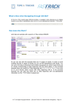
REMON G²
Client Application for Windows® User Manual
Version 0.8
March 14, 2007
© 2003-2007 Computerized Elevator Controls. All rights reserved.
REMON-G2 User Manual v0.8
Page ii
Table of Contents
1
INTRODUCTION TO REMON-G2.................................................................................1
1.1
REMON-G2 Architecture ..................................................................................................... 1
1.2
REMON-G2 Communication................................................................................................ 2
1.3
Document Scope ..................................................................................................................... 2
2
CLIENT APPLICATION SOFTWARE (CLIENT) FOR MS WINDOWS® .......................3
2.1
Installation and Configuration.............................................................................................. 3
2.2
Downloading and updating REMON-G2 Client Application Software ............................ 3
2.3
Logon ....................................................................................................................................... 4
2.4
Main Screen ............................................................................................................................ 5
2.5
Menu and Selection Tree ....................................................................................................... 5
2.5.1
Remon .............................................................................................................................. 7
2.5.2
Jobs................................................................................................................................... 7
2.5.3
Cars................................................................................................................................... 8
2.5.4
Job Management............................................................................................................... 8
2.5.5
Reports.............................................................................................................................. 9
2.5.6
Security............................................................................................................................. 9
2.6
Data Display Area ................................................................................................................ 10
3
MULTI_GROUP DISPLAY ..........................................................................................11
4
SINGLE_GROUP DISPLAY........................................................................................12
4.1
Single_Group Display Options............................................................................................ 12
4.2
Dynamic Display Scaling ..................................................................................................... 13
4.3
Car and Hall Calls Icons...................................................................................................... 15
4.4
Service Type Icons................................................................................................................ 16
5
CAR RELATED SCREENS ........................................................................................18
5.1
Diagnostic Screen ................................................................................................................. 18
5.1.1
FUTURA Diagnostic Screen.......................................................................................... 18
5.1.2
MERIDIA Diagnostic Screen......................................................................................... 19
REMON-G2 User Manual v0.8
Page i
5.2
Car Report ............................................................................................................................ 19
5.3
Car Management.................................................................................................................. 20
5.4
Fault Screen .......................................................................................................................... 21
5.4.1
Clear fault from Fault Screen ......................................................................................... 22
6
JOB CONFIGURATION..............................................................................................23
6.1
Heavy Traffic Up/Down....................................................................................................... 23
6.1.1
Up Peak .......................................................................................................................... 24
6.1.2
Down Peak ..................................................................................................................... 24
6.2
Lobby..................................................................................................................................... 25
6.2.1
Set The Alternate Lobby Floor....................................................................................... 25
6.2.2
Set The Dual (Second) Floor.......................................................................................... 25
6.2.3
Set The Rear Lobby Floor .............................................................................................. 25
7
JOB MANAGEMENT ..................................................................................................26
7.1
Set Call at a floor .................................................................................................................. 26
7.2
Toggle parameters................................................................................................................ 26
8
REPORTS ...................................................................................................................27
8.1
Individual Car Service ......................................................................................................... 27
8.2
Traffic Log ............................................................................................................................ 28
8.3
Car Service............................................................................................................................ 30
8.4
Long Wait Calls .................................................................................................................... 32
8.5
Hall Call Distribution by Floor ........................................................................................... 35
8.6
Hall Call Distribution by Time Slot.................................................................................... 36
8.7
Hall Call Traffic Summary.................................................................................................. 38
8.8
Car Traffic Summary .......................................................................................................... 39
9
SECURITY ..................................................................................................................42
9.1
Current Security................................................................................................................... 42
9.1.1
Enable Security............................................................................................................... 43
9.1.2
One Click Security ......................................................................................................... 43
9.1.3
Secure Doors, Floors and Hall Calls .............................................................................. 44
9.2
Security Settings ................................................................................................................... 44
REMON-G2 User Manual v0.8
Page ii
9.2.1
9.2.2
9.2.3
Create New Configuration.............................................................................................. 45
Load Configuration into car controller........................................................................... 45
Delete Configuration ...................................................................................................... 45
9.3
Coded Car Calls.................................................................................................................... 46
9.3.1
Enter A New Security Code ........................................................................................... 46
9.3.2
Delete A Security Code.................................................................................................. 47
9.3.3
Clear All Security Codes................................................................................................ 47
10
SERVICE ACTIVATION TIMERS............................................................................48
10.1
Service Activation Timers Interface ................................................................................... 48
10.2
Add Timer ............................................................................................................................. 49
10.3
Add Security ......................................................................................................................... 50
10.4
Edit Timer or Security Settings .......................................................................................... 50
10.5
Delete Timer or Security...................................................................................................... 51
11
SYSTEM REQUIREMENTS ....................................................................................52
12
GLOSSARY.............................................................................................................53
REMON-G2 User Manual v0.8
Page iii
1 Introduction to REMON-G2
REMON-G2 software provides a convenient, attractive and intuitive visual interface for monitoring
elevators as well as multi-group application functionality, extended analysis and control capabilities
that include building management commands, traffic analysis and playback functions. Its
convenient, easy-to-use graphic interface is based on modern processing and network technologies
for multiple-Client and multiple-Server applications.
Depending on hardware setup configuration, REMON-G2 receives and displays in real-time
elevator traffic, car diagnostic information from elevator controllers. It stores traffic data and
performs activity playback, traffic/activity analysis, generates predefined reports and provides
graphical user interface to multiple Clients over the Internet/Intranet.
REMON-G2 implements user interface and data processing for the existing SWIFT FUTURA and
SWIFT MERIDIA controllers. It replaces and enhances the older DOS version of REMON and
eliminates the need for a Remote Video Unit (RVU) and related software.
1.1
REMON-G2 Architecture
REMON-G2 presumes the use of nonproprietary off-the-shelf hardware technologies and software
platforms. REMON-G2 consists of the following elements:
Servers: Web servers with SQL compliant database and software for communication with
elevator controllers;
Clients: Client Application Software is the Microsoft Windows®-based user interface for
remote data access and presentation.
Figure 1: The REMON-G2 Architecture
REMON-G2 User Manual v0.7
Page 1
Multiple Servers and Clients can exist simultaneously within the framework. Any authorized Client
can communicate through REMON-G2 Servers with any elevator group in the network. An internal
security system provides authorized data access and information safety.
1.2
REMON-G2 Communication
REMON-G2 Clients and Servers communicate using standard TCP/IP protocol. This structure is
hardware and software independent and allows the elements to execute either on a single computer
or on several computers over a TCP/IP network with diverse communication media including
Ethernet (cable or wireless) and dial-up modem communication.
1.3
Document Scope
This document describes REMON-G2 Clients operation and usage. It does not cover REMON-G2
installation related issues (e.g. installing REMON-G2 servers and connecting to hardware,
administrating REMON-G2, entering product ID).
REMON-G2 User Manual v0.8
Page 2
2 Client Application Software (Client) for MS Windows®
The REMON-G2 Client Application Software written for MS Windows® provides the ability to
view and control real-time elevator traffic and car diagnostic information from a standard personal
computer. It also allows for the review and editing of security settings if present in installed
equipment configuration. Several screens with graphical representation of diverse elevator data are
available. The software can provide interface to review historical data. Service type and security
scheduling is available.
The actual configuration is user and hardware dependent. Not all menu items and features may be
present in a given setup.
2.1
Installation and Configuration
REMON-G2 Client Application software is based on ActiveX technology. Additional software
usually not required. The REMON-G2 Client runs in any PC equipped with Microsoft Internet
Explorer 5.5SP2 or higher that can access a REMON-G2 Server over Intranet or Internet.
2.2
Downloading and updating REMON-G2 Client Application Software
The first time your PC communicates with a REMON-G2 Server, the Client Application software is
automatically downloaded and install into your PC. Check that your Internet Explorer’s ActiveX
security controls are enabled to permit the downloading and running of ActiveX applications as
shown in Figure 2.
Figure 2: ActiveX control settings
REMON-G2 User Manual v0.8
Page 3
If your PC’s ActiveX controls are older than that of the PC running the REMON-G2 Server, the
latest version of ActiveX controls will download and run automatically. You may be prompted for
permission depending on your web browser’s security settings. In this case click “Yes” to install the
ActiveX control.
Figure 3 ActiveX download prompt
2.3
Logon
Logon is required to access any REMONG2 data. Only authorized users will have access to
REMON-G2. Accessibility is based on the user’s registered Username and Password pair (Figure
4). The REMON Administrator verifies the user’s registration and access rights in the REMON-G2
system procedure. Unauthorized users will receive an error message indicating that an invalid user
ID or password has been entered.
Figure 4 Logon prompt
REMON-G2 User Manual v0.8
Page 4
2.4
Main Screen
The main Client Application screen layout is shown in Figure 5. It consists of two frames:
•
Menu and Selection Tree (Tree) on the left
•
Data Display Area (Display) on the right.
The entire Client screen and each of its frames can be resized to fit any standard Windows® style
panel. To expand the Internet Explorer window to full screen, use the F11 key on your
keyboard.
Tree Area
Display Area
Figure 5: Main Screen, Client Application Software
2.5
Menu and Selection Tree
The Menu and Selection Tree presents a listing of the equipment being monitored by Client. The
Tree consists of the available Jobs plus related information and available menu actions. Jobs
represent an elevator group consisting of one or more cars (simplex, duplex, or multi-car). Clicking
on a Job in the Tree loads the corresponding data for that Job into the Display. Clicking on “Remon”
REMON-G2 User Manual v0.8
Page 5
root in the tree will display multigroup screen. Clicking on menu actions shows corresponding
report or management screens in Display area or loads dialog boxes.
The Tree reconfigures itself based on the current user’s authorization and the system’s
configuration. Only Tree items that are permitted to be used by the current user will be displayed.
Figure 6: Menu and Selection Tree
To expand or decrease the area of the Menu and Selection Tree frame, click and drag on the narrow
vertical border between the two frames. For convenient screen space management, The Menu and
Selection Tree frame can be minimized/restored by clicking on the “Hide/Show Tree” button in the
upper left corner of the Display.
The Client action menu is integrated into the Menu and Selection Tree. When an authorized user
clicks a Tree item that can be processed by menu commands (a Job or an individual car), its
complete branch is displayed including all available menu commands.
Clicking various Tree items will result in the actions described below. A “+” sign at the left of a
Tree item means that lower level items are nested inside. Click the “+” to display (maximize) the
nested sub-items, or “-” to hide (minimize) the displayed sub-items.
REMON-G2 User Manual v0.8
Page 6
2.5.1
Remon
The default name given to the first level (tree root) in the Tree hierarchy is the “Remon”. Clicking
on “Remon” reveals all available Jobs in a minimized “static” mode, and invokes the Multi_Group
display in the Display frame (see paragraph 0:).
Tree item
−
Remon
+
+
Job #1
Job #2
+
Job #N
Display type
Multi_Group Display
Single_Group Display
Single_Group Display
Single_Group Display
Help
Help Home Page
Clicking “Help” in the Tree frame displays the help home page. Help files are HTML files located
on every REMON-G2 Server. Help files present the user manual in HTML format.
2.5.2 Jobs
Jobs represent either single or multi-car elevator groups. When the user clicks a particular Job, the
information for that Job is displayed in the Display frame to the right (see paragraph 4 Single_Group
Display). Each Job has following subitems:
Tree item
Job # N
+ Car #1
+ Car #2
+
Car #3
+
Car #N
Display type
Single_Group Display
Configuration
Job Configuration
+
Management
Job Management
+
Reports
Reports
+
Security
Security
Service Activation Timers
REMON-G2 User Manual v0.8
Service Activation Timers
Page 7
2.5.3 Cars
Clicking the “Car” expands the branch. It has no effect on the content of the Display frame.
Tree item
Job # N
− Car #1
Diagnostic
Reports
Management
Recording and Playback
Fault Screen
+
Car #2
+
Car #3
+
Car #N
Display type
Single_Group Display
Diagnostic Screen
Individual Car Service
Car Management
Error! Reference source
not found.
Fault Screen
2.5.4 Job Management
−
Management
Set a Call at a Floor
Set Call at a floor
Toggle Parameters
Toggle parameters
REMON-G2 User Manual v0.8
Page 8
2.5.5 Reports
−
Reports
- Traffic Log for Time Period
- Car Service for Time Period
- Long Wait Calls
- Hall Call Distribution By Floor
Traffic Log
Car Service
Long Wait Calls
Hall Call
Distribution by
Floor
-
Hall Call Distribution By Time Slot
Hall Call
Distribution by
Time Slot
-
Hall Call Traffic Summary
Hall Call Traffic
Summary
-
Car Traffic Summary
Hall Call Traffic
Summary
2.5.6 Security
−
Security
Current Security
Current Security
Security Settings
Security Settings
Coded Car Call Codes
REMON-G2 User Manual v0.8
Coded Car Calls
Page 9
2.6
Data Display Area
The Display frame on the right side of the main screen presents real-time status information about
each elevator that the user is authorized to access including direction of travel, door status, and
service mode. The content of the Display is based on the current Menu and Selection Tree choice.
The following main graphical displays can appear in data display area:
•
Multi_Group Display
•
Single_Group Display
•
Diagnostic Screen
•
Job Configuration Screen
•
Security Screens
•
Reports Screens
•
Playback Screen
•
Service Activation Timers Screen
Additionally, there are several setup and information screens and dialogue boxes.
REMON-G2 User Manual v0.8
Page 10
3 Multi_Group Display
Clicking on the "Remon" tree root in the Menu and Tree frame invokes the Multi_Group Display
shown in Figure 7: Multi_Group Display for Windows® Client Application. This screen presents
status information about each elevator accessible to the Client Application for a current user (i.e. if
this username/password is present on remote server that server will return information to local one).
Screen size and resolution determine the number of Jobs that can be presented in the Multi_Group
display at one time.
If a given group is in Up Peak or Down Peak mode it will be surrounded with a frame.
Up/
down
peak
Figure 7: Multi_Group Display for Windows® Client Application
The information presented for each car is explained in Figure 9.
If communication with some group fails the “Disconnected” text can appear instead of group
pictures.
REMON-G2 User Manual v0.8
Page 11
4 Single_Group Display
Clicking on a particular “Job” (group) item in the Tree invokes the Single_Group Display that
dynamically depicts the real-time hoistway position of all the elevators in the selected group. If
there is insufficient screen space to display all cars simultaneously, the user may minimize the Tree
frame by clicking on the “Hide/Show Tree” button.
The Single_Group Display presents the following:
•
General job information (job name, peak status, number of floors and cars)
•
Car position and direction of travel
•
Hall calls assignments to the individual cars
•
Car calls
•
Car door status
•
Car service status (mode)
The actual number of cars, floors, and floor numbers correspond to the configuration of the selected
Job.
Right clicking anywhere in the Single_Group Display activates the Car Context Pop-up Menu for
switching the control between dynamic and static display modes and setting Car and Job
management functions and operational parameters. The structure of the context menu is shown in
Figure 8. Some menu items can be grayed out depending on the current user access rights.
Figure 8: Car Context Pop-up Menu
Press Static Display item to switch view to Static/Dynamic mode. Car and Job Management
functionality is described in 5.3 and 7, respectively.
4.1
Single_Group Display Options
Two options are available for displaying information about the cars in a Job/group. These are
shown in Figure 9: “Dynamic” and “Static” car representation.
REMON-G2 User Manual v0.8
Page 12
Car userfriendly
name
Service type
icon
Car
direction
Car with
opening
doors
Car userfriendly
name
Hall call
assigned to
this car
Car
direction
Floor
number
“Next call
up” icon
Dynamic mode
Service type
icon
Static mode
Figure 9: “Dynamic” and “Static” car representation
•
“Dynamic” display. This option shows real time hoistway movement and status, and requires
more screen space. The following conditions are displayed with this option: service mode front
and rear car calls (with floors), front and rear hall calls (with floors and directions), and Next
Call up (Automatic mode only). The various car and hall call icons are shown in Table 1: Hall
and Car Call Icons. By default, the Single_Group is displayed in Dynamic mode.
•
“Static” display. This option is more compact but displays less information. The following
conditions are displayed with this option: front and rear door status (open/half open/closed),
service mode (if applicable), car position (current floor), the presence of front and rear hall calls,
and car direction.
4.2
Dynamic Display Scaling
The Dynamic Display presents up to 29 continuous landings.
REMON-G2 User Manual v0.8
Page 13
Figure 10 Normal Sngle_Group screen (number of floors < 17)
When more than 17 landings are present, the horizontal “bars” are halved in height and the size of
the car icon is reduced by 60% as shown in the following figure.
Figure 11: Scaled Single_Group screen (number of floors > 17 and < 29)
REMON-G2 User Manual v0.8
Page 14
When there are more than 29 floors to be displayed, the 60% reduced car icon is used with each
horizontal bar representing multiple floors. The actual floor position of each car is displayed to the
left of the car icon.
Actual Floor
Scaled Hoist way
Figure 12: Scaled Single_Group screen (> 29 floors)
In Figure 12, the hoistway is scaled to about 3 floors per horizontal bar. As the car leaves floor “L”
and heads up to “10,” you will see the car icon move to the first light blue horizontal bar above the
“L” landing and stay there while the car passes floors 1, 2 and 3. Then the car icon will move up to
the next bar (dark blue) as the car passes floors 4, 5 and 6. The process continues until the car
reaches its destination
4.3
Car and Hall Calls Icons
The following hall and car call icons are used in both the Multi_Group and Single_Group displays
reflecting real-time data from the elevator controllers.
Icon
Call Type
Icon
Call Type
Hall Call Up
Rear Hall Call
Hall Call Down
Front And Rear
Call
REMON-G2 User Manual v0.8
Page 15
Car Call: Rear
Car Call: Front
Car Call: Front And
Rear
Table 1: Hall and Car Call Icons
4.4
Service Type Icons
The various types of elevator service states and car statuses that are monitored by REMON-G2 are
shown in the following table.
Icon
Service Mode
Icon
Service Mode
Automatic
VIP Service
Out of Service
from Car Controller
Code Blue
“Next call up”
Fire Service
Homing
Attendant Service
Loss of Hall Call Power
Independent “IND”
Service
Loss of Power
Simplex/IR service
Service Protection
Rear IR service
Loss of Communication
Service Protection
Dispatch Lost
Emergency Power
Recall
Timed-out Auto
Service Protection
from Group
REMON-G2 User Manual v0.8
Page 16
Icon
Service Mode
Icon
Service Mode
Out of Service
from Group
Safety
Lobby
Disc front
Init
Disc rear
Count wgt
Earthq
MG
Stop sw
Inspection
Load bypass
Security
Up peak
Down peak
Table 2: Service Types
REMON-G2 User Manual v0.8
Page 17
5 Car Related Screens
5.1
Diagnostic Screen
The Diagnostic Screen displays car diagnostic information. The view changes according to the
controller connected to the REMON Server. The following elevator controllers are currently
supported by REMON:
•
SWIFT FUTURA (CEC)
•
SWIFT MERIDIA (CEC)
5.1.1 FUTURA Diagnostic Screen
A car-specific, real time CEC SWIFT FUTURA Diagnostic Screen is shown below. The Job
(group) to which the car belongs is indicated in the upper right corner of the screen. General car
information and current state are indicated at the bottom of the screen.
Figure 13: FUTURA Diagnostic Screen
REMON-G2 User Manual v0.8
Page 18
The FUTURA Diagnostic Screen presents up to eight 24-LED data sets that correspond to FUTURA
SMI I/O boards. The abbreviated names of the selected boards (taken form the FUTURA
SPU/CCU) are identified in the pull down window at the top of each data set. Users can change the
SMI boards to be displayed by clicking the pull down arrow and selecting the desired board. Board
inputs are displayed on a red background; and outputs are displayed on a black background.
5.1.2 MERIDIA Diagnostic Screen
The MERIDIA Diagnostic Screen consists of several fields displaying names and values of ICC
boards’ I/O lines as well as some other known fields.
The diagnostic screen for MERIDIA has 8-LED IIC panes.
Figure 14: MERIDIA Diagnostic screen
5.2
Car Report
See section 8.1 for detail on car service report.
REMON-G2 User Manual v0.8
Page 19
5.3
Car Management
The following car management functions are available in the dialog box shown in Figure 15. This
box can be accessed from the Single_Group display by right clicking on the desired car, and
selecting “Car Management” from the menu box:
•
Set a front or rear call at a floor (the “Rear” radio button may have no effect depending on actual
hardware settings)
•
Select a floor for homing
•
Independent Service Activate
•
Independent Service Deactivate
•
Independent Service Disable (Disables user to Activate or Deactivate Independent Service
through Remon G2)
•
Independent Service Enable (Enables user to Activate or Deactivate Independent Service
through Remon G2)
•
Homing Service Activate
•
Homing Service Deactivate
•
Attendant Activate
•
Attendant Deactivate
•
Car to Lobby Activate
•
Car to Lobby Deactivate
•
Car to Lobby with Door Closed Activate
•
Car to Lobby with Door Closed Deactivate
•
Lobby Independent Activate
•
Lobby Independent Deactivate
•
Special Service Activate
•
Special Service Deactivate
REMON-G2 User Manual v0.8
Page 20
Figure 15 “Car Management” dialog box
5.4
Fault Screen
Fault screen can be used to review faults that are reported by FUTURA/MERIDIA controllers. It is
displayed by clicking on “Fault screen” Menu and Tree item.
The screen outline is shown in Figure 16.
REMON-G2 User Manual v0.8
Page 21
Figure 16 REMON-G2 Fault screen
In the left column the registered faults are listed. Selecting a fault automatically displays detailed
fault information in the right part of the screen. The description of the fault is shown on top of the
screen. Faults in the left column can be sorted by fault number, occurrence time and car position at
the moment of fault using drop down lists at the bottom of the column. Choosing different values
from these lists applies filters immediately.
Both parts of fault screen can be scrolled if they do not fit on the screen.
5.4.1 Clear fault from Fault Screen
There is a clear fault check box near the left column on the Fault screen. Select the fault you want to
clear from the left column and then place a check in the clear fault check box. The fault will be
removed from the list of faults in the left column.
REMON-G2 User Manual v0.8
Page 22
6 Job Configuration
A screen for setting heavy traffic, and lobby parameters to controller is available for authorized (by
access level) users by clicking a “Configuration” item in the tree displays parameters setting
interface.
Figure 17. Job Configuration Screen
The screen consists of several zones related to up peak, down peak, lobby. The corresponding
parameters are located in each zone. “Toggle” buttons enable or disable the corresponding feature
status. Changing parameter values initiates writing them to controller flash immediately.
For further detail on configuration parameters, refer to FUTURA or MERIDIA user documentation.
6.1
Heavy Traffic Up/Down
Pane for Heavy Traffic Configuration is shown below.
REMON-G2 User Manual v0.8
Page 23
Figure 18. Heavy Traffic SetUp Pane
6.1.1 Up Peak
During heavy up, the cars at the lobby are loaded one at a time (standard) and only the doors of the
next car are open. As the car becomes loaded, or the loading time expires, the car leaves and another
car becomes next. Special provisions can be implemented to permit multiple car loading.
A car completes its up trip after it has answered its car calls and any up hall calls assigned to it. It
then reverses and proceeds to the lobby floor, provided the system is still in heavy up. The down hall
calls can be answered by any car when assigned.
When the incoming traffic becomes lighter, SWIFT controller de-allocates cars from the lobby
accordingly. The other cars park with their doors closed at the landing they last served.
Up Peak Car Call Count
•
The number of trips, in a time interval, with more than 2 car calls registered from the Lobby
Floor which will trigger UP Peak Operation.
•
This must be a value between 1 and 20.
Up Peak Load Switch Count
•
The number of trips, in a time interval, which will trigger UP Peak Operation.
•
This must be a number from 1 to 15.
Up Peak Duration Time Interval
•
The minimum duration Up Peak will last after being triggered.
•
This must be a value between 10 and 255 seconds.
To set up Heavy Traffic parameters use appropriate pane on Job
6.1.2 Down Peak
SWIFT controller automatically recognizes heavy outgoing or down traffic by monitoring the recent
and short-term traffic pattern, the number of down hall calls, their ETA's and the actual waiting
time. During this mode, the down hall calls are given preferential service to handle the traffic which
can occur in the evening or other time during the day. All cars assigned for Next Up, or other
similar service, are released. Cars arriving at the lower dispatching terminal light their lantern and
remain at the terminal for the same length of time as for any other floor. The available car(s) are
dispatched immediately to floors or to a sector of floors with the highest down waiting time, or
alternatively to the floors with the most down calls in the recent history buffer. All down hall calls
REMON-G2 User Manual v0.8
Page 24
of down traveling cars are assigned based on which car has best potential arrival time. Down peak
traffic mode has priority over up peak.
Down Peak Average Call Time
If the average Down Call ETA exceeds this value, Down Peak Operation will occur.
•
This must be a value between 10 and 960 seconds.
Set The Down Peak Duration Time Interval
•
The minimum duration of Down Peak after being triggered.
•
This must be a value between 10 and 255 seconds.
After the selection is entered press TOGGLE button is needed to change controller settings. When
user clicks TOGGLE button the new settings are written to REMON database also.
6.2
Lobby
6.2.1 Set The Alternate Lobby Floor
This feature allows the location of the lobby floor to be changed between two designated floors,
which can be field adjustable. Selection of one of the two lobbies can be activated manually or by
means of REMON-G2 service activation service. Dual lobby service overrides this feature.
Figure 19. Lobby Settings Pane
To set the alternative lobby floor press “down narrow” box to drop down the list of available floors.
Make a choice (floor’s number indicated on the left of the box) and press TOGGLE button to update
controller settings and REMON database.
6.2.2 Set The Dual (Second) Floor
This feature permits the dispatching of cars from two simultaneous main floors (field adjustable),
each of which can have a next car. The selection of the secondary lobby floor can be activated
manually or by means of REMON-G2 service activation service
Follow the same procedure for setting the alternative lobby floor.
6.2.3 Set The Rear Lobby Floor
Follow the same procedure for setting the alternative lobby floor.
REMON-G2 User Manual v0.8
Page 25
7 Job Management
7.1
Set Call at a floor
The function is available either through MenuTree or Car Context Pop-up Menu. To set a call after
function activation in Set Hall Call window set floor number, Up/Down and Rear/Front attributes
and press “Set call” button as shown on Figure 20. Set Hall Call.
Figure 20. Set Hall Call
7.2
Toggle parameters
To toggle parameters check appropriate box and press SET as shown on Figure 21. Toggle Job
Parameters.
Figure 21. Toggle Job Parameters
REMON-G2 User Manual v0.8
Page 26
8 Reports
Reporting feature allows reviewing historical system activity data collected for some predefined
time. There are several types of reports available that cover different aspects of REMON-G2
functionality.
Please note that data collecting time range is set by system administrator and is initially 7 days. All
data older than 7 days (or other period set by administrator) are deleted from the database and
cannot be reviewed.
8.1
Individual Car Service
The “Individual Car Service” report displays service type changes for a car within time period.
Unlike others, this report is available by clicking “Reports” item located below “Car” level.
To create a report for a given car:
•
Click on the car and then click on its underlying report.
•
Fill “From”, “To” boxes to set up report request parameters. The time range input field is a
custom calendar control that provides convenient date and time selection. The parameters
affect the report contents and view.
•
Click “Submit” button. Requested data displays in area below the date/time range selection
fields as shown in Figure 22. Individual Car Service Report Screen. If the list is long user
will have to scroll the page up and down to review it.
Figure 22. Individual Car Service Report Screen
REMON-G2 User Manual v0.8
Page 27
Download report as textual *.csv (comma separated values) document by pressing “Download CSV
file” reference at the bottom of the screen for further processing in table processing program, MS
Excel for example.
Click “Send” button to form report as a separate HTML page in a new Internet Explorer window. It
can be printed and sent over email using Internet Explorer “File->Print” and “File->Send” menu
items if the computer has printer and email client installed. The generated HTML page outline is
shown in Figure 23. Individual Car Service Report HTML.
Figure 23. Individual Car Service Report HTML
Print report (looks similar to Figure 23. Individual Car Service Report HTML) using standard web
browser Print function (Print button on browser toolbox or File-Print from browser menu). Printing
the report on a color printer will provide better report view result. To improve hard copy view
operator should enlarge the report area as much as possible before printing (can be done using
mouse by sliding frame splitter to the left). Printing can be done from a separate page generated by
clicking “Send” button.
8.2
Traffic Log
The “Traffic log” report allows viewing details of Group traffic historical log. The report displays:
•
Hall Call times, origin (front or rear hall) and directions
•
Wait times corresponding to Hall Calls
•
Car service status changes (if requested)
•
Summary (number of calls within the period and average wait time).
To generate report:
•
Click this tree item to open report request screen on the left.
REMON-G2 User Manual v0.8
Page 28
•
Fill “From”, “To” boxes and check boxes to set up report request parameters. If “Car
service” check box is checked the table may interfere with car service change messages (if
any). The time range input field is a custom calendar control that provides convenient date
and time selection. The parameters affect the report contents and view.
•
Click “Submit” button Requested data displays in area below the date/time range selection
fields. If the list is long user will have to scroll the page up and down to review it. After
receiving the report the user can adjust time range and resubmit his request. The report is
redisplayed then with different data corresponding to new time range.
To provide reasonable system response and reasonable network load the data output is limited to
500 lines. If there are more than 500 lines in the report an information string (“More data is
available”) is displayed in the last line of the list.
Figure 24. Traffic Log Report Screen
The data are also displayed as a histogram. The average wait time (dark grey) and the longest wait
time (light grey) within the selected time interval are displayed for each car within the Group.
Download report as textual *.csv (comma separated values) document by pressing “Download CSV
file” reference at the bottom of the screen for further processing in table processing program, MS
Excel for example.
Click “Send” button to form report as a separate HTML page in a new Internet Explorer window. It
can be printed and sent over email using Internet Explorer “File->Print” and “File->Send” menu
items if the computer has printer and email client installed. The HTML attachment outline is shown
in Figure 25. Traffic Log Report HTML. It contains:
•
Job number and its user-friendly name
•
Time range
•
Report request parameters (up calls, down calls)
REMON-G2 User Manual v0.8
Page 29
•
Report data organized in a table
•
Simple data analysis: separate numbers of up and down hall calls (with their type listed),
total number of hall calls (a sum of two previous ones), average wait time, and maximum
wait time.
Figure 25. Traffic Log Report HTML
Print report (looks similar to Figure 25. Traffic Log Report HTML) using standard web browser
Print function (Print button on browser toolbox or File-Print from browser menu). Printing the report
on a color printer will provide better report view result. To improve hard copy view operator should
enlarge the report area as much as possible before printing (can be done using mouse by sliding
frame splitter to the left). Printing can be done from a separate page generated by clicking “Send”
button.
8.3
Car Service
The “Car service” report displays car service within the Group for corresponding time slot. It allows
comparing cars’ operation to optimize their workload within the Group. The report contains number
of car calls, trips and “Out of service” time for each car in the group.
To generate report request:
•
Click this Menu Tree item to open report request screen on the left.
•
Fill “From” and “To” edit boxes to enter time interval in the data display area. The time
range input field is a custom calendar control that provides convenient date and time
selection.
•
Click “Submit” button to display the report in the data display area as shown in Figure 26.
Car Service Report Screen. After receiving the report the user can adjust time range and
resubmit his request. The report is redisplayed then with different data corresponding to new
time range.
REMON-G2 User Manual v0.8
Page 30
Figure 26. Car Service Report Screen
The data are displayed as a table with number of car calls, trips and out of service time during the
requested period for each car.
Download report as textual *.csv (comma separated values) document by pressing “Download CSV
file” reference at the bottom of the screen for further processing in table processing program, MS
Excel for example.
Click “Send” button to form report as a separate HTML page in a new Internet Explorer window. It
can be printed and sent over email using Internet Explorer “File->Print” and “File->Send” menu
items if the computer has printer and email client installed. The generated HTML page outline is
shown in Figure 27. Car Service Report HTML. It contains:
•
Job number and its user-friendly name
•
Time range
•
Report request parameters
•
Report data organized in a table
REMON-G2 User Manual v0.8
Page 31
Figure 27. Car Service Report HTML
Print report (looks similar to Figure 27. Car Service Report HTML) using standard web browser
Print function (Print button on browser toolbox or File-Print from browser menu). Printing the report
on a color printer will provide better report view result. To improve hard copy view operator should
enlarge the report area as much as possible before printing (can be done using mouse by sliding
frame splitter to the left). Printing can be done from a separate page generated by clicking “Send”
button.
8.4
Long Wait Calls
The “Long Wait Calls” report allows finding out long wait calls that happened within time range
and their regularities. The report displays times, origin (front or rear hall) and directions of hall calls,
and corresponding wait times. A short summary (number of calls within the period and average wait
time) is also displayed.
To generate report request:
•
Click this Menu Tree item to open report request screen on the left.
•
Fill “From” and “To” and “Long Wait Time” edit boxes to enter time interval in the data
display area. The time range input field is a custom calendar control that provides convenient
date and time selection. The latter edit box allows entering the desired long wait time
threshold. The default long wait time value is 45 seconds. Check or clear desired check
boxes to retrieve up and/or down calls information.
REMON-G2 User Manual v0.8
Page 32
•
Click “Submit” button to display the report in the data display area as shown in Figure 28.
Long Wait Time Report Screen. After receiving the report the user can adjust time range and
resubmit his request. The report is redisplayed with different data corresponding to new time
range.
Figure 28. Long Wait Time Report Screen
The data are displayed as a table with following fields:
•
Floor number
•
Call direction
•
Call registration
•
Wait time.
If the list is long user will have to scroll the page up and down to review it. To provide reasonable
system response and reasonable network load the data output is limited to 500 lines. If there are
more than 500 lines in the report an information string (“More data is available”) is displayed in the
last line of the list.
The data are also displayed as a histogram. The average wait time (dark grey) and the longest wait
time (light grey) within the selected time interval are displayed for each floor in the Group.
REMON-G2 User Manual v0.8
Page 33
Download report as textual *.csv (comma separated values) document by pressing “Download CSV
file” reference at the bottom of the screen for further processing in table processing program, MS
Excel for example.
Click “Send” button to form report as a separate HTML page in a new Internet Explorer window. It
can be printed and sent over email using Internet Explorer “File->Print” and “File->Send” menu
items if the computer has printer and email client installed. The generated HTML page outline is
shown in Figure 29. Long Wait Time Report HTML. It contains:
•
Job number and its user-friendly name
•
Time range and report creation time
•
Report request parameters (long wait threshold)
•
Report data organized in a table
•
Simple data analysis and graphical data representation.
Figure 29. Long Wait Time Report HTML
Print report (looks similar to Figure 29. Long Wait Time Report HTML) using standard web
browser Print function (Print button on browser toolbox or File-Print from browser menu). Printing
the report on a color printer will provide better report view result. To improve hard copy view
operator should enlarge the report area as much as possible before printing (can be done using
REMON-G2 User Manual v0.8
Page 34
mouse by sliding frame splitter to the left). Printing can be done from a separate page generated by
clicking “Send” button.
8.5
Hall Call Distribution by Floor
The “Hall Call Distribution by Floor” report helps in traffic analysis. It displays number of hall calls
and call distribution by wait time for each floor. Percentage of wait times and total number of
corresponding calls are calculated.
To generate report:
•
Click this Menu Tree item to open report request screen on the left.
•
Fill “From” and “To” and “Up Hall Calls” and “Down Hall Calls” check boxes to enter the
required parameters in the data display area. These checkboxes are used to allow user to
separately review up or down hall calls. The time range input field is a custom calendar
control that provides convenient date and time selection.
•
Click “Submit” button to display the report in the data display area as shown in Figure 30.
Hall Call Distribution By Floor Report. After receiving the report the user can adjust time
range and resubmit his request. The report is redisplayed with different data corresponding to
new time range.
Figure 30. Hall Call Distribution By Floor Report
REMON-G2 User Manual v0.8
Page 35
The report consists of a table and a graph. The table represents floors, number of calls, total and
average wait times for each floor and distribution of calls with different lengths per floor. The graph
displays average wait time distribution per floor.
Download report as textual *.csv (comma separated values) document by pressing “Download as
*.csv file” reference at the bottom of the screen for further processing in table processing program,
MS Excel for example.
•
Click “Send” button to form report as a separate HTML page in a new Internet Explorer
window. It can be printed and sent over email using Internet Explorer “File->Print” and
“File->Send” menu items if the computer has printer and email client installed
Print report using standard web browser Print function (Print button on browser toolbox or File-Print
from browser menu). Printing the report on a color printer will provide better report view result. To
improve hard copy view operator should enlarge the report area as much as possible before printing
(can be done using mouse by sliding frame splitter to the left). Printing can be done from a separate
page generated by clicking “Send” button.
8.6
Hall Call Distribution by Time Slot
The “Hall Call Distribution by Time Slot” report helps in traffic analysis. It displays number of hall
calls and call distribution by wait time for each time slot. Percentage of wait times and total number
of corresponding calls are calculated.
To generate report:
•
Click this Menu Tree item to open report request screen on the left.
•
Fill “From” and “To” and “Time slice” edit boxes as well as “Up Hall Calls” and “Down
Hall Calls” check boxes to enter the required time parameters in the data display area. These
checkboxes are used to allow user to separately review up or down hall calls. The time range
input field is a custom calendar control that provides convenient date and time selection.
•
Click “Submit” button to display the report in the data display area.as shown in Figure 31.
Hall Call Distribution By Time Slot Report Screen. After receiving the report the user can
adjust time range and resubmit his request. The report is redisplayed with different data
corresponding to new time range. To provide reasonable system response and reasonable
network load the data output is limited to 500 lines. If there are more than 500 lines in the
report an information string (“More data is available”) is displayed in the last line of the list.
REMON-G2 User Manual v0.8
Page 36
Figure 31. Hall Call Distribution By Time Slot Report Screen
The report consists of a table and a graph. The table represents:
•
Time interval
•
Number of calls per time interval
•
Total and average wait times for each time interval
•
Distribution of calls with different lengths per time interval.
•
Graph displays average wait time distribution per time interval.
Download report as textual *.csv (comma separated values) document by pressing “Download as
*.csv file” reference at the bottom of the screen for further processing in table processing program,
MS Excel for example.
•
Click “Send” button to form report as a separate HTML page in a new Internet Explorer
window. It can be printed and sent over email using Internet Explorer “File->Print” and
“File->Send” menu items if the computer has printer and email client installed
Print report using standard web browser Print function (Print button on browser toolbox or File-Print
from browser menu). Printing the report on a color printer will provide better report view result. To
improve hard copy view operator should enlarge the report area as much as possible before printing
REMON-G2 User Manual v0.8
Page 37
(can be done using mouse by sliding frame splitter to the left). Printing can be done from a separate
page generated by clicking “Send” button.
8.7
Hall Call Traffic Summary
The "Hall Call Traffic Summary” report displays information about hall call traffic:
•
Number of calls
•
Number and percentage of long wait calls
•
Average wait time and availability for each time slot.
To generate report request:
•
Click this Menu Tree item to open report request screen on the left.
•
Fill “From” and “To” and “Timeslice” and “Long Wait Time” edit boxes to enter the
required time parameters in the data display area. The time range input field is a custom
calendar control that provides convenient date and time selection.
•
Click “Submit” button to display the report in the data display area as shown in Figure 32.
Hall Call Traffic Summary Report Screen. After receiving the report the user can adjust time
range and resubmit his request. The report is redisplayed with different data corresponding to
new time range. To provide reasonable system response and reasonable network load the
data output is limited to 500 lines. If there are more than 500 lines in the report an
information string (“More data is available”) is displayed in the last line of the list.
Figure 32. Hall Call Traffic Summary Report Screen
REMON-G2 User Manual v0.8
Page 38
The report consists of a table and a graph. The table represents time intervals, number of calls per
time interval, average wait time for each time interval, percentage of long wait calls and availability
percentage. The graph displays average wait time (dark grey bars) and percentage of long wait hall
calls (light grey bars) per time interval.
Download report as textual *.csv (comma separated values) document by pressing “Download as
*.csv file” reference at the bottom of the screen for further processing in table processing program,
MS Excel for example.
Click “Send” button to form report as a separate HTML page in a new Internet Explorer window. It
can be printed and sent over email using Internet Explorer “File->Print” and “File->Send” menu
items if the computer has printer and email client installed. Report contains:
•
Job number and its user-friendly name
•
Time range
•
Report request parameters (time slice and long wait time threshold)
•
Report data organized in a table
•
Simple data analysis (number of calls and long wait time calls vs. time slice graph).
Print report using standard web browser Print function (Print button on browser toolbox or File-Print
from browser menu). Printing the report on a color printer will provide better report view result. To
improve hard copy view operator should enlarge the report area as much as possible before printing
(can be done using mouse by sliding frame splitter to the left). Printing can be done from a separate
page generated by clicking “Send” button.
8.8
Car Traffic Summary
The "Car Traffic Summary” report displays information about car traffic for each car within group
during given time interval:
•
Number of trips, one floor runs, door cycles and car calls
•
Availability (out of service) for each time slot.
To generate report request:
•
Click this Menu Tree item to open report request screen on the left.
•
Fill “From” and “To” edit boxes to enter the required time parameters in the data display
area. The time range input field is a custom calendar control that provides convenient date
and time selection.
•
Click “Submit” button to display the report in the data display area as shown in Figure 33.
After receiving the report the user can adjust time range and resubmit his request. The report
is redisplayed with different data corresponding to new time range.
REMON-G2 User Manual v0.8
Page 39
Figure 33. Car Traffic Summary Report Screen
The report consists of a table and a graph. The table represents number of trips, one floor runs, door
cycles, car calls, and other parameters. The graph displays the same parameters as pie charts to
allow easy comparison between cars.
Download report as textual *.csv (comma separated values) document by pressing “Download as
*.csv file” reference at the bottom of the screen for further processing in table processing program,
MS Excel for example.
Click “Send” button to form report as a separate HTML page in a new Internet Explorer window. It
can be printed and sent over email using Internet Explorer “File->Print” and “File->Send” menu
items if the computer has printer and email client installed. Report contains:
•
Job number and its user-friendly name
•
Time range
•
Report time interval
•
Report data organized in a table
•
Report data pie charts.
Print report using standard web browser Print function (Print button on browser toolbox or File-Print
from browser menu). Printing the report on a color printer will provide better report view result. To
REMON-G2 User Manual v0.8
Page 40
improve hard copy view operator should enlarge the report area as much as possible before printing
(can be done using mouse by sliding frame splitter to the left). Printing can be done from a separate
page generated by clicking “Send” button.
REMON-G2 User Manual v0.8
Page 41
9 Security
The security features allow authorized user to manage built-in FUTURA or MERIDIA security
features (if present in current installation). This item is never displayed in Menu Tree if security is
not programmed into the equipment.
Among available security management features are the following:
•
Viewing current hall call and car call security configuration
•
One-click enabling or disabling security
•
Securing or unsecuring a single floor or all floors
•
Applying one of predefined security configurations stored in the database
•
Editing predefined security configurations
•
Listing floors where given security code is used
•
Listing security calls for given floor
•
Assigning given security code to a floor
•
Assigning given security code to all floors
•
Deleting given security code from a floor
•
Deleting given security code from all floors
9.1
Current Security
The control is displayed after clicking “Current Security” item in the left Menu Tree frame.
REMON-G2 User Manual v0.8
Page 42
Figure 34. Current Security Screen
Current Security Screen displays the current security layout. The user can modify the security by
using the mouse to enable or disable security, secure halls and cars as described below. The scroll
bars are used to display calls on taller buildings. Scaling is not supported on this view.
9.1.1 Enable Security
To use security configurations FUTURA or MERIDIA controller must be put into “Enable security”
state. This is done using the corresponding checkbox on Current Security Screen. Checking the
checkbox results in sending “Enable security” command to controller. Unchecking the checkbox
results in sending “Disable security” command to controller.
9.1.2 One Click Security
“One Click Security” – Formerly known as “Guard Station” or “Total Building Security” is
activated by checking the box labeled “One Click Security”. All floors and Car Calls will be locked
except on the Guard Station level. “Enable security” command is also issued to controller to process
the case when security has been disabled at the moment of clicking “One Click Security”. “Guard
Station Level” control defines the floor that will not be secured when clicking the “One click
security” checkbox on Current Security Screen.
REMON-G2 User Manual v0.8
Page 43
9.1.3 Secure Doors, Floors and Hall Calls
Clicking on Hall Call narrow buttons and cars icons toggles the security status of hall call or car call
for particular floor and car. Click on the yellow padlock to secure the entire floor (car calls and hall
calls / fronts and rears).
The settings are sent to controller immediately.
IMPORTANT NOTICE. Some time (several seconds) is needed to re-read the latest controller
settings after change so there is a delay between clicking on car or hall call button and visual
response. If there were several clicks the result is undefined (usually only the last click is
processed).
9.2
Security Settings
The screen allows creating security configurations, saving them to database, reviewing, deleting,
and loading to FUTURA or MERIDIA controllers.
Figure 35. Edit Security Settings
Clicking Security Settings item from Menu Tree opens Edit Security Settings Screen to create or to
manage predefined security configurations as shown on the picture below. The screen initially loads
with current security configuration displayed.
REMON-G2 User Manual v0.8
Page 44
To display other previously defined security configurations select the corresponding name from
“Configuration name” drop-down box. The configuration being displayed can be loaded into
FUTURA or MERIDIA controller immediately but will have effect only if the controller is currently
in “Enable security” state (see 9.1.1).
The security configurations created using this screen can be later used to set security in Service
Activation Timers (see section 10).
9.2.1 Create New Configuration
To create a new security configuration:
•
First select a new name on the Configuration Name Text Box.
•
Click on the Front or Rear Elevators to secure the Car Calls for that particular car on that
particular floor.
•
Click on the Hall Calls Front or Rear (Up and Down) to secure that particular call and particular
direction for all the cars.
•
Click on the yellow padlock to secure the entire floor (car calls and hall calls / fronts and rears).
•
Save the configuration by press “Save” button on the top of the screen.
The saved configuration appears in “Add security” combo box in “Service Activation Timers”
window.
9.2.2 Load Configuration into car controller
To load selected security configuration into car controller:
•
Drop down Configuration Name Text Box by pressing down narrow on the left. Select a name
from dropped down list of available configurations.
•
Load the configuration by press “Load” button on the top of the screen. You will see the
message while loading security configuration to car controller and after a certain interval another
message describing the result of the operation.
Loading security configuration to car controller is a lengthy process. To start the process certain
conditions must be met (e.g. master car in group must not be moving) so overall delay could be a
minute or so. A message box is displayed as security is loaded and another message box appears on
security loading result.
9.2.3 Delete Configuration
To delete security configuration from the database:
•
Drop down Configuration Name Text Box by pressing down narrow on the left. Select a name
from dropped down list of available configurations.
•
Delete the configuration by press “Delete” button on the top of the screen. After you answer
“Yes” to confirmation message the configuration will be deleted.
The deleted configurations will not appear in “Add security” combo box in “Service Activation
Timers” window more. Also, these configurations will not be loaded through Service Activation
Timers interface if scheduled before so be very careful.
REMON-G2 User Manual v0.8
Page 45
9.3
Coded Car Calls
This feature allows listing, adding, editing and deleting security codes for a given floor or floors as
shown on Figure 36. Security codes allow protecting selected landings from unauthorized access.
For further information on security codes please consult your equipment user manual.
Figure 36. Coded Car Calls
Before any of the following operations, choose front or rear car calls using a dropdown box in the
top left corner of the screen.
To list floors for code click desired code in “Select code to view floors” column. The “Select Floor#
to View Codes” column will be updated by placing a “Security Key” on the floors that the particular
code affects.
To list codes for floor user should click desired floor in “Select floor to view codes” column. The
“Select Code# to View Floors” column will be updated by highlighting the codes that are associated
with that floor.
The “Max Codes Per Floor” displays the controller limited number of codes that can be assigned to
a single floor. This value is for reference only and cannot be changed.
9.3.1 Enter A New Security Code
To add a code user should enter the desired code in “Enter new security code” field on Figure 36.
Coded Car Calls. The entered code can be assigned to all floors or for individual floor, in the latter
case the floor should be chosen from dropdown list. Pressing “Apply” will set the code.
REMON-G2 User Manual v0.8
Page 46
9.3.2 Delete A Security Code
To delete a code user should enter the desired code in “Delete security code” field on Figure 36.
Coded Car Calls. The entered code can be deleted from all floors or from individual floor, in the
latter case the floor should be chosen from dropdown list. Pressing “Apply” will delete the code.
The changes will be visible in the right columns immediately.
9.3.3 Clear All Security Codes
To delete all security codes for particular floor choose the desired floor and then use “Clear Codes”
button.
REMON-G2 User Manual v0.8
Page 47
10 Service Activation Timers
Service activation timers are implemented in REMON software. To provide service activation for
given job the connected REMON server must be up and running.
The following services can be configured to start and stop at a schedule:
•
Up Peak Service
•
Down Peak Service
•
Alternate Lobby Service
•
Dual (Two) Lobby Service
•
Rear Lobby Service
•
Parking Service
•
Inconspicuous Riser Service
•
Rear (Other) Riser Service
•
Loading security configuration
10.1 Service Activation Timers Interface
The control is displayed after clicking “Service Activation Timers” or underlying items in the left
frame.
Figure 37. Service Activation Timers Screen
The interface displays the services using calendar controls. Clicking in calendar in the right column
displays the selected day in the middle column with active service periods listed in white bars. The
REMON-G2 User Manual v0.8
Page 48
names of the services are displayed within the bars. Right Click on the timetable activates pop-up
menu as shown below.
Figure 38. Service Activation Timer Pop Up Menu
10.2 Add Timer
Timers for any of available services can be added, edited and deleted by using appropriate panel. To
add timer, right click in the corresponding string at corresponding time and choose “Add -> Timer”
from appeared pop up context menu. Clicking in exact region is not obligatory but convenient
because the opened dialog box is filled with values corresponding to click region. The dialog box is
displayed on the picture below.
Figure 39. Add/Edit Timer Panel
•
Choose the desired service from a dropdown list
•
Set service start and service stop times
•
Choose the desired service start period (once, every day, several days within a week, a list of
days). To add days to the list, user should use calendar control. To remove days from list,
user should mark a day and hit “Delete” button on the keyboard.
•
Click “OK” button to add timer or “Cancel” to cancel setting service
REMON-G2 User Manual v0.8
Page 49
10.3 Add Security
To load security configuration at a given time right click in the corresponding string at
corresponding time and choose “Add -> Security” from appeared context menu. Clicking in exact
region is not obligatory but convenient because the opened dialog box is filled with values
corresponding to click region. Managing security configurations is described in 9.2
The dialog box is displayed on the picture below.
Figure 40 "Add/Edit Security” dialog box
•
Choose the desired security configuration from a dropdown list
•
Set configuration load time and disable time
•
Choose the desired configuration load period (once, every day, several days within a week, a
list of days). To add days to the list, user should use calendar control. To remove days from
list, user should mark a day and hit “Delete” button on the keyboard.
•
Accept timer by click “OK” button. Cancel setting service by clicking “Cancel” button.
Be careful when working with security configurations as overlapping can bring to confusion. Avoid
inserting one security configuration in the middle of another as the inserted configuration will
disable the bounding one on its exit.
10.4 Edit Timer or Security Settings
To edit timer, right click on the timer on Service Activation Timers Screen to pop up context menu.
•
Choose “Edit” from appeared context menu. Add/Edit Timer dialog box is displayed filled
with selected timer data.
•
Change times and periods.
•
To confirm changes, user should click “OK” button. To cancel editing click “Cancel” button.
REMON-G2 User Manual v0.8
Page 50
10.5 Delete Timer or Security
To delete timer right click the appropriate timer on Service Activation Timers Screen to pop up
context menu and choose “Delete” from appeared context menu. The timer will be deleted from
database and from Service Activation Timers Screen.
REMON-G2 User Manual v0.8
Page 51
11 System Requirements
The computer(s) running REMON-G2 Client Application must run under Windows®
98/ME/2000/XP and an Internet Explorer 5.5SP2 or later web browser with enabled ActiveX
controls.
REMON-G2 User Manual v0.8
Page 52
12 Glossary
CCN: “Car Communication Number.”
CCU: “Car Control Unit” in MERIDIA. It is functionally equivalent to FUTURA’s SPU. It has a
limited floor number.
CTG: “Car To Group” bus and is the RS-485 bus interconnecting the SPUs within the group.
FPI: “Floor Position Indicator.” These are the two characters that represent the floor displayed on
an RVU.
HC: “Hall Call” bus. Hall call requests come to all SPUs or CCUs over this bus.
HTML: “Hypertext Markup Language,” a hypertext document format used on the World-Wide
Web.
ICC: An I/O module used in MERIDIA. It has 8 I/O lines. Inserted into IOC. Can be either input or
output (all 8 lines together; no individual direction change).
IOC: A carrier board connected to one of the CCU’s buses in MERIDIA. An IOC carries a number
of ICCs.
Job: A group of one or more elevators cars with SPUs interconnected over an RS-485. Also
referred to as Single_Group.
RPU: “Remote Processing Unit.” Also known as an SPU-V. Requires additional polls during
operation.
RVU: “Remote Video Unit.” It is used to obtain group and car data from SPUs. It is obsolete and
will be replaced by the REMON-G2 Decode Application.
SMI: A board with up to 24 solid state relays (SSR) and chip controllers for FUTURA. Can be
connected to an SPU or RPU using RJ-45 cable. Each SMI can be addressed by SPU. Here are
abbreviations for some of the following known SMIs:
VFC: Velocity/Fault Controller
MRC: Motor Room Interface Controller
GPx: General Purpose I/O
TOC: Top Of Car controller
COP: Car Operating Panel I/Os. Manages fire switches, car light etc.
CC1: Car Call I/Os. Manages car call buttons I/O.
HLUD1: Hall Lantern I/Os.
HC1: Hall Call I/Os.
SPU: “System Processing Unit” in FUTURA. Each SPU manages its own car.
SPU-V: An extension unit used in FUTURA when catering to more than 60 floors. Also known as
an RPU (Remote Processing Unit.) Requires additional poll during operation
REMON-G2 User Manual v0.8
Page 53