1
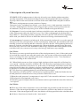
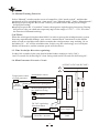
H U M M E R W I N D G E N E R A T O R MANUAL HUMMER-3KW HUMMER Wind Generator is built by three parts: Generator body, Control system, Rectifier-inverter system. The control system can adjust the operational status of the wind turbine according to the timely wind information and wind generator performance index, and take reasonable and effective protection to the wind turbine to ensure its long-term security and stability in operation. The rectifier-inverter system integrates the instability current that generated by the wind turbine into a stable power supply efficiently through the rectification and invertion and then supply to the grid or electrical appliance. ANHUI HUMMER DYNAMO CO., LTD The content of the Manual has been carefully proofread before publication, but there might be still some differences between the photographs and their physical goods. Foreword Dear Owner, Congratulations! You have just purchased the most technologically advanced small-scale wind turbine system in the world--HUMMER wind turbine. We appreciate your purchase, and are proud of providing the excellent product to you. Before going any further, please completely read the owner’s manual, although it is easy to install your wind turbine by yourself. You will find our great efforts to satisfy your requirements in the aspects of design,manufacture, operation, applicability, etc. Please keep the manual carefully for further reference. If you have any questions or comments, we would like to hear from you. Again, thanks for your purchase and wish you enjoy the convenience that HUMMER wind turbine brings you. Thanks for using HUMMER wind turbine — High Quality and Original Te c h n o l o g y CONTENT Part I: The installation of the Wind Generator Main Body 1. Package 2. Product Structure 3. Description of System Function 4. Cable for Transmission and Control Communication 5. Product Parameters 6. Power Curve 7. Speed-reduce Direction-regulating Motor 8. Assembling Steps of FreeStanding Tower System 9. Assembling Steps of Guy Tower 10. Assembly Precautions 11. Troubleshooting 12. Daily Maintenance 13. Safety Precautions 14. Assembling of the Anemometer (1) (2) (3) (6) (6) (7) (7) (8) (17) (20) (21) (22) (22) (23) Part II: Wind Generator Control System 1. The Introduction of Control System 2. The Specific Structure of HUMMER Controller 3. Switches and Terminal Blocks of the Controller 4. Connection of Generator and Control System 5. The Display and Operation of the Touch-screen 6. System Time Setting 7. Precautions for Operating the Controller 8. Troubleshooting for HUMMER Controller (25) (25) (26) (27) (31) (36) (36) (37) Part III: Off-grid Wind Generator Output System 1. Panel Function and Operation Instruction 2. Precautions 3. Basic information 4. Inverter 5. Operation of Inverter LCD 6. HUMMER-3KW Off-grid Inverter (single phase) wiring Switch 7. Connection of Wind generator and Off-grid Inverter 8. HUMMER-3KW Off-grid Inverter Technical Parameters 9. Contact Us 10. Disclaimers (39) (40) (40) (41) (41) (42) (43) (44) (44) (44) Part I The Installation of the Wind Generator Main Body The main body of the HUMMER- 5 KW wind generator could be assembled both with guy tower or wireless tower. We specially developed the “hydraulic tower system” for the wireless tower which effectively reduces the wind turbine’s installation and maintenance costs. Related operations, please refer to <Manual of Hydraulic Tower System > 1. Package Contents BOX No. BOX Name Size of box (L*W*H) Bill of materials 3KW-1 Generator box 460×460×560 Generator, User’s manual -1 Controller box 550×395×220 HUMMER-3KW wind generator controller -2 Rectifier box 650×465×235 Rectifier/Dumping controller -3 Dumping load box -4 Inverter box 690×580×285 HUMMER-3KW off-grid inverter Rotor blades box 2400×295×260 Blades(3), L=2.3m 3KW-2 3KW-3 3KW-4 * 3KW-5 Yaw shaft box Tower box Dumping load 805×405×445 3235×410×410 1. Yaw shaft (50m cable) * 2. Pedestal, Tower pin 3. Anemometer, Dogvane, and 2 pieces supporting poles 4. Accessory Box: * a. M12 OO turnbuckle (8 pieces) * b. M8 wire clamp (48 pieces) c. Battery connection wires (1.5m/piece×2 ) d. Battery connection wires (0.3m/piece×14) e. M14*60screw(24 pieces) * f. M14*60screw(6 pieces) g. One bottle of lubrication h. One acutilingual bottle for adding lubrication 1.Tower (4 segments) 2.Φ8 wire rope(4pieces for 15.5m) 3.Φ8 wire rope(4pieces for 13m) 4.Φ8 wire rope(8pieces for 1m) Note: The items marked with “ * ” are the accessories for guy tower. 1 2. Product Structure HUMMER-3KW wind generator consists of generator body and yaw shaft. The generator body consists of generator, blades . Yaw shaft system has the direction-regulating function. And consists of gearbox, direction-regulating DC motor and dogvane, etc.. 5 3 4 2 1 6 10 11 7 16 17 8 9 12 14 15 13 Name NO Name NO 1 Generator 10 DC 24V power supply 2 Blades 11 DC 24V direction-regulating motor 3 Yaw shaft protection cover 12 Speed-reduction of DC24V motor 4 Gland cover 13 Gear box 5 Lighting rod (selection match) 14 Wind generator output cable terminals 6 Dogvane 15 Generator temperature transmitter 7 Support of dogvane 16 Generator rotation speed probe 8 Signal wire terminal block Relay 17 Yaw shaft angle probe 9 2 3. Description of System Function HUMMER-3KW wind generator is directly driven by rotor blades without any other speedup equipment. The patented wind generator featuring high efficiency and super legerity settles in the cone which is in front of the rotor blades and is helpful to radiate heat. The whole wind generator system consists of 6 parts: Generator body ( including rotor blades ), yaw shaft, tower, wind generator controller, rectifier / dumping load / inverter, and energy storage system ( for off-grid system use accumulator; for gird-tied system, power will be transferred to grid directly.) 3.1. Dogvane: It receives wind signal, indicates wind direction, and read the average value of the angle measured by the dogvane every 120s. If the reading angle by the dogvane is larger than 10°, the wind generator controller will drive the DC 24V direction-regulating motor with yaw shaft to deviate to fulfill the function of facing wind automatically. 3.2. Anemometer: It measures wind speed, if the measured wind speed is over the required wind speed for the wind generator to start continuously within 30s, the wind direction auto tracking system will start up and the controller will drive the DC 24Vregulating-direction motor to seek the wind direction automatically. When the blades are the facing the wind direction, they can receive the maximum wind energy, and when the blades parallel to the wind direction, they can not receive any wind energy, and hence stop running. CAUTION: The factory-set start-up wind speed value of the wind generator is 1m/s. If the wind speed is less than the required start-up wind speed value, the system will keep in standby mode. Users can change the start-up wind speed of the wind generator in the “User Parameter” window according to the actual needs. 3.3. When blades rotate too fast owing to high wind speed, the controller will alarm for “over speed”. And the controller will drive DC 24V direction-regulating motor with yaw shaft to deflect wind direction about 30° at this time. If the blades still rotate too fast, the controller will further drive blades to deflect wind direction 60°, and then the blades will be parallel to wind direction and stop running. After 5mins, the controller will drive the DC 24V direction-regulating motor to seek wind direction again. The controller will drive the DC 24V direction-regulating motor make the blades deviate 90°and parallel to wind direction if any of below situations occurs. I.When the wind generator’s temperature is up to145°C.the controller indicates “over temp” II.Wind speed is too high and over 18m/s III.Rotation speed is higher than the maximum rotation speed and the controller indicates “over speed” CAUTION: When any of the above situations occurs, the blades are parallel to wind direction. In 5 minutes, if the alarm signal disappears, the controller will drive the blades to seek wind direction. If the alarm signal still exists, the blades will keep parallel to the wind direction. All above functions are based on the “Auto mode”. 3 3.4. Manual Tracking Function: Select “Manual” window on the screen of controller, click “mode switch”, and then the track mode will be switched from “Auto mode” into “Manual mode”. Under “Manual mode”, ●keeping on pressing the “Reversion” button, yaw shaft rotates and the positive angle keeping increasing; ●keeping on press the “Corotation” button, the negative angle keeping increasing, During this process, the yaw shaft can stop at any angle in the range of -270 º ~ +270 º to realize the function of Manual tracking. CAUTION: When the wind speed is higher than 18M/S, in order to protect the wind generator system from any unpredictable damage, user can use “manual track” function to set the blades aside or back to wind direction which can make the wind generator stop working. Or set the blades 30° ~ 45° off the wind direction. In this way, the wind energy received by the blades will decrease, and the rotation speed will slow down. 3.5. Time Needed for Direction-regulating: It takes 180 seconds for the yaw shaft with the blades rotating a circle (360°). And 15 seconds for deflecting 30° from facing wind and 45 seconds for deflecting 90°. 3.6. Wind Generator S chematic C ircuit AC220V(or DC160~DC300V) L - N Dogvane sensor DC 24V regulatingdirection motor Relay Rectifier / inverter 4 DC 24V power supply II Load Fuse Wind generator rotor speed probe Wind generator Measurement probe for yaw shaft revolving SIEMENS CPU Temperature transmitter Power switch Anemometer sensor DC 24V power supply I Temperature sensor of wind generator + 3.7. Diagram for the Wire Connection of Yaw Shaft and Generator Name Generator Head V Temperature Transducer Output Cable of Generator DC24V Power Supply II V+ V+ V- L V- Dogvane Signal Wire Dogvane Temp2 + Temp3 - G.Speed VV+ W.Direct VV+ 1 2 3 Signal Wire Terminal Block W. G. G. Temperature Direct + - Direct Speed Dogvane Signal Wire V- N Temp1 Temperature Transducer Signal Wire Terminal Block Relay Generator Rotation Speed Wire Speed Reducer Generator Rotation Speed Wire Directionregulating Motor Generator Signal Wire High Voltage Power Supply for Yaw Shaft Gear Box Generator Temperature Wire Output Cable Connector V+ U Output Cable Connector (inter changeable) Output Cable of Generator Generator Temperature Wire Terminal Connect to Mark CAUTION: Please connect the 4 main cables from generator (2 output cables, 1 rotation speed wire, and 1 temperature signal wire) and dogvane signal wire to the terminal block on yaw shaft accordingly. 5 4. Cable for Transmission and Control Communication As it is shown in the following picture, there are three main cables. 2 One is the AC output cable of wind generator with the specification of 2* 6 mm . One is high voltage power supply wire for DC24V direction-regulating motor with the specification of 2*1 mm², it will be transformed by Power Supply II into 24VDC on yaw shaft and then supplied to DC24V direction-regulating motor. One is for the signal transmission for the whole system with specification of 8*0.3 mm². They are for generator rotation speed signal, yaw shaft rotation angle signal, generator temperature signal, dogvane signal and the power wires for them. High Voltage Power Supply Input(L) High Voltage Power Supply Input(N) U V Generator Output Cable Generator Signal Wire 5. Technical Parameters Rated power(W) 3000 Maximum output power(W) 4500 Charging voltage (V) DC 180V Blade quantity 3 Rotor blade material GRP Rotor blade diameter(m) Φ4.8 Start-up wind speed (m/s) Rated wind speed (m/s) 2.5 Rated rotating rate (r/min) 265 Wind energy utilizing ratio (Cp) 0.4 Generator output Single-phase frequency conversion AC Rated charging current (A) 16.7 The maximum charging current(in a short time)(A) 28 Output AC frequency (Hz) 0~360 Generator efficiency >0.8 10 Wireless tower diameter(mm) Φ440× Φ127×12000( 2 segments ) Guyed tower diameter(mm) Φ140×3000×4( 4 segments ) Tower height(m) Wireless tower:12m; Guyed Tower: 12m The weight of generator(kg) 71.8 Battery 12V 150Ah/200Ah 15 pieces 6 6. Power Curve HUMMER-3KW Wind Generator 7. Speed-reduce Direction-regulating Motor 7.1. Speed-reduce regulating-direction motor is a motor that require a power supply of DC 24V and consists of two parts as the speed reducer and direction-regulating motor. Normally, it consumes 35W to 60W to regulate the direction of the blades. When there is strong wind or too heavy load, the instantaneous consumed maximum power might reach up to 250W. If the consumed power surpasses 250W, the controller will protect it automatically and cut off the power supply to direction-regulating motor. And power will be supplied again in 120 seconds. 7.2. Power Supply to Speed-reduce Direction-regulating Motor: The AC220V from the grid or DC160~DC300V power supply will be transmitted to DC 24V power supplyII which is on the yaw shaft, converted into DC 24V and supplied to the direction-regulating motor through the relay, which is under the control of HUMMER controller. 7 8. Assembling Steps of Freestanding Tower System 8.1. Open the Packing HUMMER-3KW wind generator freestanding tower system consists of 7 packing boxes: generator box, inverter box, blades box, yaw shaft box, controller box, rectifier box, dumping load box, (towers are packed individually with no packing box). 8.2 Precasting Pedestal and Digging Hole 8.2.1 Precasting the Tower Pedestal Precasting tower pedestal by concrete (C25) Size of the concrete of tower pedestal:1.05m×1.05m×1.8m (L*W*H) Size of reinforced concrete: 4.5m×0.3m×0.7m (L*W*H) Size of tower pedestal: Φ700×Φ440×16mm 12 16 12-M24 120 150 screw thread length 1250 Φ700 Φ580 12-Φ26 Φ440 HUMMER-3KW Wireless Tower Anchor Screw Working Diagram 8 Anchor bolt flange 12-M24 anchor bolt HUMMER-3KW Pedestal’s Concrete Base Specification 1.05m*1.05m 1100 300 4.5m*4.5m 700 HUMMER-3KW Wireless Tower Freestanding Tower Pedestal Diagram Tower (2 segments) Tower pedestal 12-M24 Anchor bolt Ground Concrete base CAUTION: The M24 anchor screw and pedestal fixed plate shall be used only after special anticorrosion treatment, such as Hot Galvanizing. 9 8.2.2. Dig Hole Dig the hole as per the given size in “3KW Pedestal’s Concrete Base Specification” , well weld the tower pedestal and put it into the hole after anti corrosion treatment, then butt weld the reinforcing steel bar in the concrete with the tower pedestal (before welding, use a leveling rod to keep it level, incase the tower is slantwise after its being erected). Fill with soil after pouring concrete. CAUTION: Please use paper or other materials to encase the bolts on pedestal to avoid the damage from the splashing cement. 8.3. Blades Assembling 8.3.1. Pull the steel wire through any of the holes on the generator connection base. Use crane to pull out the generator from the packing box, then put it on the sponge cushion, take off all the nuts, bolts and blades fixing flange from it. ! WARNING: Generator Rotation Speed Probe There is a generator rotation speed probe on the Generator Head. When lifting the generator head, tie the steel wire at this position is forbidden. 8.3.2. Take out the blades, connect the 3 blades properly to the flange , t hen cover the flange and fasten the nuts.(As blades need accurate position, bolts must be fastened tightly against blades. Please use a hammer to hit the bolts in the corresponding hole). M12 nuts Spring washer Blade Flat washer M12*90 outer hexagonal bolt Flange CAUTION: The side marked with “FRONT” shall be adown and windward. All the 3 rotor blades have passed the balance test, it needs to be used together. Please do not disorderly use the rotor blades belonging to other generators. Sponge cushion 10 Generator 8.4. The Connection of Generator Head and Yaw shaft 8.4.1. Lifting the yaw shaft Put steel wires through the lifting hole under the soleplate of the yaw shaft. Lift the yaw shaft with the hook. Then, after the yaw shaft has been lifted, slowly descend it until the best position to fix it with the generator on the ground. 8.4.2. The assembly of generator head and yaw shaft. Focus the screw hole in the generator connector with those in the yaw shaft soleplate, and then fix the generator to the yaw shaft with M14*60 bolt, and then fasten the nuts. Slowly descend the hook,until reaches the best position for connection Generator connection base Focus the holes on generator connection base with those on yaw shaft. Then connect and fasten the generator with M14*60 bolts. M14*60 bolt 11 8.4.3. Connect the two output cables of the generator (U/V) with the connector, and fasten them tightly. (These two cables can exchange the location.) 8.4.4. Connect the three small cables in the generator rotation speed wire (G. Speed / V- / V+) to the respect signal cable terminals on the yaw shaft. 8.4.5. Connect and fasten the generator temperature wire to the temperature transducer which is at the side of gearbox. + Temp1 Temp2 - Temp3 Generator Temperature Wire Temperature Transducer CAUTION: There are three outgoing cables for measuring generator temperature, connect the one marked “Temp 1” to the terminal block on the top of the temperature transducer, and the other two (Temp2/ Temp3) to the below terminal blocks , as shown in the pictures. 8.5. The Connection of Generator and Tower 8.5.1. Drive the cable under the yaw shaft with a wire and put it through from the top of the tower to the bottom hole until it is taken out. 8.5.2. Fasten the supporting base of the yaw shaft with the flange on top of the tower with M14*60 hexagonal bolts, and then deadlock the nuts. M14*60 Hexagonal Bolts Spring Washer Flat Washer 1.2m Generator Output Cable HUMMER-3KW Tower and Yaw shaft Connection Diagram 12 8.6. The Assembling of the Support and Dogvane 8.6.1. Connect dogvane support to the yaw shaft with M6*20 inner Hexagon screw,fasten tightly. Use M6*20 screw to fasten dogvane support 8.6. 2. Put the yaw shaft protection cover to the yaw shaft through the support of dogvane. Put the cover to yaw shat horizontally 8.6. 3. Put the seal ring into the sealing cover, then insert the support of dogvane into the sealing cover and tighten them. Water-proof seal ring and seal cover 8.6.4. Hold up the protection cover, then pull in the dogvane signal wire from the top of the support and pull it out from the bottom of the support, then connect the three small dogvane data wires (W. Direct/V-/V+) to the corresponding location of the signal wires terminal block. 8.6.5. Put the dogvane onto the support. Make the zero-position hole of the dogvane fit with screw hole on the supporter and then fasten it with the cross screw. 13 Pull-in the dogvane wire from the top of the dogvanesupport and put-out fromthe hole at the bottom of support. Dogvane Wire End (W.Direct / V- / V+) Lock the dogvane on thesupport with the zero-locking screw. 8.7. A ssembling of the Lightning Arrester If you selected the lighting rod, please fix the lighting rod well to on the bottom plate of the yaw shaft when you assemble the support of the dogvane before installing the protection cover of yaw shaft. 8.8. Covered the yaw shaft with protection cover, fix it to the yaw shaft with M6*18cross screw. Tighten the water proof cover along the dogvane support. Cross Screw for Fastening Yaw Shaft Cover 14 8.9. Erecting the Tower Suggested method: Use the crane Tie the top of the tower with canvas strap. Then hang the strap on the hook of the crane. Gradually lift the arm of the crane and the generator is erected simultaneously, until the tower is vertical to the ground. Making an aim at the anchor screws, slowly put down the tower and fasten it. See as the following photos. CAUTION: I. It is important for you to consult with a local specialized tower installation technician, better with who has electric tower or outdoor billboard erection experience. II. Make sure the two power cables are short circuited and connected together in order to avoid blades rotation during the process of erecting. Operation method: Insert two generator output cables into the corresponding connector (Wind generator) in Rectifier/Dumping controller and then fasten them. Place “Wind generator stop/operation” switch at the “stop” position. III. Safety shall be first concern in the process of erection and adjusting, be careful of tower falling, which would dndanger the safety of the field worders. Tower Erection Picture I Canvas strap Tower Erection Picture II 15 Tower Erection Picture III Tower Erection Picture IV 16 9. Assembling Steps of Guy Tower 9.1. Open the Packing Box HUMMER-3KW guyed tower wind turbine consists of 8 packing boxes including generator box, inverter box, blades box, yaw shaft box, tower box, controller box, rectifier box and dumping load box. 9.2 Precasting the Tower Pedestal and Digging Hole 9.2.1 Precasting the Tower Pedestal Pre-make one tower pedestal and four guy pedestals by concrete (C25). Size of the concrete of tower pedestal: 600×600×450 mm (L*W*H) Size of the concrete of guy pedestal: 700×400×200mm (L*W*H) Size of tower pedestal: 380×380×12mm (L*W*H) 300*300 R30 300*300 4-Φ26 600*600 380*380 R20 155 4-M22 anchor bolt 125 160 12 3KW Pedestal 450 200 1500 3KW Pedestal Hole Planform 700 Φ30 16 600*600 9000 HUMMER-3KW Anchor Installation CAUTION: The fixed loops on guy pedestals and the connecting rods shall be made of stainless steel. Ordinary steel can be used only after special anticorrosion treatment, such as Hot Galvanizing. 17 9.2.2 Digging the Hole Dig the hole refer to the given size, then put the tower pedestal & guy pedestals inside the hole, at last level up the ground. The fixed loop on guy pedestal should be exposed. Guy hole Pedestal hole Guy hole: 700*400*1500(L*W*H) Pedestal hole: 600*600*450(L*W*H) Center distance between guy hole and pedestal hole: 9000 Unit: mm 9000 9.3 Assembling Assembling is the same as steps of assembling wireless tower system. (Please refer to the part of the wireless tower assembling procedures in this manual.) 9.4 Erecting the Wind Generator Suggested method: Use the crane Fasten the steel wire on the crane with the top of the tower and tighten it. Slowly lift the crane arm and erect the whole generator until the tower is vertical to the ground. Hold the position of the crane and fasten the steel wire around, then tighten each guy one by one, and make the tower vertical to the ground. HUMMER-3KW Guy Tower Erection Picture 18 CAUTION: I. It is important for you to consult a local specialized tower installation technician, who has electric tower or outdoor billboard erection experience. II. Make sure the two cables from the wind generator are short circuited connected in order to avoid blades rotation during the process of erecting. III. The joint point of each steel wire and guy ring should be insured with safety lock to avoid the loose of turnbuckle during the adjustment. IV. Safety shall be first concern in the process of erection and adjusting, be careful of tower falling, which would endanger the safety of the field workers. Tower (4 segments) Guyes (4 pcs) Turnbuckle(4 pcs) Safety Rope Tower Pedestal Pedestal pin Output cables Pedestal Anchor Bolt HUMMER-3KW Diagram of Guy Tower Connection 19 Anchor 10. Assembly Precautions 20 ML 100 Lubrication Hole of Gear Box 1L 460# Oil for the Gear Outlet Hole of Gear Box 100 20ML Acutilingual Bottle 10.1. The ideal distance between 2 sets of 3KW wind generator is 20m. 10.2. When a product is to be assembled, open the cover of the gear box lubrication hole and about 0.5L engine oil should be inputted with the acutilingual bottle. CAUTION: The 460# oil is special for the gear, can not be used as speed-reducer of direction-regulating motor oil, or other equipment oil. CAUTION: Oil used for speed-reducer is 46# hydraulic oil which has been filled before they leave factory. 10.3. Make sure the two output cables of the generator are short circuit connected to avoid blades rotation during the process of tower erection.( if the wind speed is too fast during the tower erection, the blade will rotating slowly, the wind speed would better be slower than 10m/s when installing. ) 10.4. Make sure the tower must be vertical to the ground. If the tower is not vertical but tilt to one side, the extra energy will be consumed by the direction-regulating motor when working. 10.5. Please evaluate the length of wire rope before erecting the tower. Every connection point of turnbuckle is fitted with twist lock to prevent tower falling down because of turnbuckle looseness. 10.6. Any group blades are made up with 3 blades which have passed the rigorous test of balance and can not be exchanged between two different generators, otherwise the blades will run abnormally which will result in serious shaking. Open the packing box with extreme caution to avoid any disorderly taking the blades. 20 10.7. For off grid system, the power generated by wind generator will charge batteries after rectified, different model collocates different numbers of batteries, please strictly follow the user’s manual to choose the right number to make sure the output voltage of wind generator will well matched with the voltage of batteries. If batteries’ voltage is too high or too low, the generator system may work improperly or some parts of the system could be burn out. 10.8. Emergency Shut-down Please use the “Manual mode” function to set the control model to “Manual track”,press the “Manual stop” button to drive the yaw shaft to deflect 90º to let the blades parallel to wind direction, before typhoon or gale(such as more than grade 10) coming. Then put the “wind generator stop/operation switch” to the “Stop” position. The wind generator will stop work. After the heavy wind, please put the “ wind generator stop/operation switch” to the “ Operation ” position, and switch the “Manual mode” into “Auto mode”, the wind generator will work normally . CAUTION: The “wind generator stop/operation switch” only can be switched from “Operation” to “Stop” when the blades stop rotating or rotate at very low speed. If switch when the blades rotating at a very high speed, it will cause a big shock to the wind generator or burn the generator. 10.9. The Connection of the Batteries HUMMER-3KW wind generator is matched with 15 PCS batteries (12V, 150AH or 200AH). Firstly, connect the 15 PCS batteries in series. Secondly, connect the batteries to inverter. Please connect the battery anode (+) and cathode (-) strictly to the inverter anode (+), the cathode (-) terminals. CAUTION: Please charge the new battery with state grid prior to using. 11. Troubleshooting Problems Possible Cause Blades can’t turn steadily, shake a lot Unbalance of the blades Check whether misuse the blades which are not belonging to same unit. Good wind, but blades rotate very slowly 1. The two output cables are short circuited 2. Generator was burnt out 1. Check whether the two output cable are short circuited. 2. Change the generator. Generator lost load Check whether the output cables are broken and fuses are melted down or not. Get the output cables and fuses reconnected. Blades rotate faster than usual 21 Solution 12. Daily Maintenance The HUMMER wind turbine is highly reliable and does not need frequent maintenance. However, the overall system of wind turbine must be inspected and maintained regularly to ensure the system’s normal operation. 12.1. Guy Inspection Check the tower guys for loosening and fasten any loosened wiring timely. Carry out this inspection time after time in the first three months after tower erection. It is also necessary to check wiring after gales. 12.2. Screw Inspection Check and fasten the screws on flange, yaw shaft and tower. This work should be done every year. 12.3. The lubrication in the gear box has to be renewed biennially. 12.4. Transmission Line Inspection Check whether the connecting points of the cables are well-connected or corroded. 12.5. Battery Maintenance Regularly check and maintain the batteries bank as per the maintenance requirements of the batteries. If there is no wind for a long time, don’t have the batteries in electric deficit state too long. Charge it with grid power in time. CAUTION: Do not stand near the turbine during gale weather. It is recommended that you lay down the tower or bind blades with tower in the case of approaching extremely rough weather (such as typhoons, hurricanes, etc) to avoid accidents. 13. Safety Precautions HUMMER wind generator is designed under strict safety regulations. However, any electrical and/or mechanical equipment during installation or operation can cause potential inherent dangers, if the proper safety precautions are not taken. Please read the following safety precautions thoroughly before you choose the wind generatorlocation, plan to install or operate the turbine. 13.1. Mechanical Hazards Rotating blades can move fast enough that the tip of a blade is almost invisible, which can cause serious injury or damage to anything it contacts. Do not install the turbine where anyone can come in contact with the blades. 13.2. Electrical Hazards The product is equipped with needed protection device to avoid electrical dangers. But potential dangers still exist in the turbine, so please be careful during the process of connecting wires and other electronic equipments. 22 Undersized wire or a bad connection can cause over-current electrical dangers and overheating in wiring systems which could cause fire or other personal dangers. Thus it is important to check the wire connections in normal maintenance. Please strictly follow the manual when you operate the inverter. Fire will be caused by the short circuit of batteries. In order to avoid this threat, please make sure the fuses are in a good condition. 13.3. Assembly Hazards Safety should be first concern. 14. Annex: Assembling of the Anemometer 14.1. Please refer to the steps of the dogvane assembling. Pull the anemometer cable through the support first and then fasten the anemometer to the support with a screw. 14.2. Settle the anemometer support to a place near to the wind generator and can correctly detect wind speed. Or assemble anemometer onto a stand. Make sure that the anemometer should be in same height with the wind generator. This can ensure the wind speed data that anemometer send to the wind generator controller is correct. 14.3. Anemometer Connecting Wire is 30m Anemometer Zero-Locking Screw Support Anemometer Wire Stand (matched by user) HUMMER Controller 8 9 23 10 Part II Wind Generator Control System HUMMER wind generator control system mainly used to control the DC24V direction-regulating motor, which drives yaw shaft deviate to seek wind direction, thus to make sure the wind generator make use of the wind energy efficiently. 1. The Introduction of Control System The system adopts SIEMENS CPU and touch-screen control, which will alarm and adjust the running status of the wind generator automatically and protect the wind generator promptly when there are abnormal situations during the operation of the wind generator. Thus it is much easier and more reliable for user to monitor the operation of wind generator. HUMMER wind generator control system is capable of quick reaction to wind signal in wind site, monitoring and adjusting the operation of wind generator accordingly. The user can view various of operation data of the wind generator on the touch-screen LCD; and manual control the wind generator to fulfill the function of manual seek wind, manual stop and forced start-up etc. through the touch-screen,(Detailed functions, refer to 5.5) HUMMER controller is designed basing on more human-oriented, and contains the “User Parameter Setting” interface. Users can set the start-up wind speed under the mode of “seek the wind direction automatically”,and the protect wind speed for deflection in heavy wind according to the actual needs. The whole wind generator control system can be simplified as the following Figure. S NS SIE S IEME N Wind turbine COM 0O 0 1 2 3 0 1 2 3 4 5 4 5 6 7 3-0 211 -055 12 CPU PWR 020 IO Touch-screen SIEMENS CPU 2. The Specific Structure of HUMMER Wind Generator Controller COM CPU 1 Power Switch 2 Fuse Tube AC500V/4A PWR 3 3 4 5 6 7 2 2 5 4 8 DC24V Power SupplyI SIEMENS CPU SIEMENS Extension Module Terminal Block 7 Touch Screen 6 1 8 9 Upper Cover of Controller 9 Terminal Block Cover 10 Wire Inlet Hole 10 25 3. Switch and Terminal Blocks of the Controller 3.1. Power Switch I. Grid-tied ON OFF II. Off-grid L Connect to State-grid L(AC180~260V) N Connect to State-grid N + - Connect to Anode(+) of Battery Bank Connect to Cathode(-) of Battery Bank L N PE 3.2. Terminal Blocks High Voltage Power Supply Wire Generator Signal Wire Anemometer Wire Signal wire for Rectifier & Dumping controller UPS Wire 1 2 3 4 5 6 7 8 9 10 11 12 13 14 15 16 L DC24V power supply II(on the yaw shaft), L N DC24V power supply II(on the yaw shaft), N PE GND 1 V- DC24V- 2 Q0.0 Yaw shaft contra rotation signal 3 Q0.1 Yaw shaft clockwise rotation signal 4 I0.0 Generator rotation speed signal 5 I0.2 Yaw shaft angle signal 6 200 Wind direction signal 7 202 Generator temperature signal 8 V+ DC24V+ 9 V- DC24V- 10 I0.1 Anemometer signal 11 V+ 12 V- 13 204 14 206 DC24V+ DC24VVoltage signal Current signal 15 V+ 16 I0.3 DC24V+ UPS signal 26 4. Connection of Generator and Control System 4.1. Assembling Steps for HUMMER Controller and Wind Generator Connection Step 1: Take off the terminal block cover, separately connect the generator signal wires (1/2/3/4/5/6/7), Yaw shaft high voltage power supply cables (L/N), anemometer signal wires(8/9/10), and UPS signal wire (15/16, grid tied selection) to corresponding terminals on the controller. Step 2: Put the “Power switch” at “OFF” position, and then connect the high voltage power supply wire to it. Off grid system: Connect the batteries anode (+) to “DC input +”, cathode (+) to “DC input -”. Grid tied system: Connect State- grid “L/N” separately to the “AC input L/N” switch ports. Step 3: Put the “Power switch” in the position of “ON”. 4.2. Control System Connection Diagram HUMMER C ontroller AC220V or DC160~300V Wind Generator - N COM N L FUSE FUSE UPS V+ V+ V- V- Anemometer Selection of grid-tied system PWR DC24V Power Supply + L CPU L PE L ON OFF N CPU 1 2 3 4 5 6 7 8 9 10 11 12 13 14 15 16 N High Voltage Power Supply Wire Generator Signal Wire Anemometer Wire Rectifier/Dumping Controller 11 12 13 14 Earth Bar 27 PE CAUTION: User should make HUMMER controller reliably grounding. Grounding wire should be not less than 1.5 mm². User can choose to connect the grounding bar to the ground or to the city grid GND terminal. Only after the HUMMER controller was reliably grounding, can you go on the above connection procedure. Annex: Pictures for all the Wires Connect to the Controller High Voltage Power Supply Wire Generator Signal Wire Anemometer Wire UPS Output Wire PE L N 4.3. Power Supply for the Controller 4.3.1. HUMMER controller can be used for both grid-tied system and off-grid system. When used in grid-tied system, power supply is from grid. Voltage range is AC180V ~ AC260V, 50Hz or 60Hz. When is used in off-grid system, the power supply from batteries, voltage range is DC 160V~300V. 4.3.2. After connecting in the power switch, the High voltage power supply will be divided into two paths: One connects to the DC24V power supply I on the controller, and be converted to 24V DC and supply power for SIEMENS CPU. The other connects to the DC24V power supply II on the yaw shaft. And then supply power for the direction-regulating motor through the relay (KA1, KA2). This can avoid the voltage reduction problem for direction-regulating motor power supply which owes to long wire distance. 4.3.3. User can control the power supply for the controller freely by using the switch on the controller. Please put this switch on the “OFF” position before connecting the power supply wire and signal wires. Put the switch on the position of “ON” after connection. 4.4. UPS Connect in (Selection of Grid-tied System). For grid-tied wind generator system, when grid is off, the electricity generated by the generator only can be consumed by the dumping load. Meanwhile, as there is no power supply for the control system, it can’t control the yaw shaft to turn away from the wind direction. UPS can be a good choice for the user. 28 4.4.1. UPS function for grid-tied system: When grid running normally, grid supply power to the control system directly. When grid is off, UPS will invert and output power to control system and send signals to SIMENS CPU. CPU will order the yaw shaft to turn 90° to make the generator stop working. After the grid being restored, as the grid supplies electricity for the control system again, UPS will stop inverting but send signal to CPU, Then CPU will make order asking the system searching for wind again and turn into normal working condition. 4.4.2. UPS Connect Steps: Step 1: Connect the UPS output cables (PE/L/N) to the corresponding terminals (PE/L/ N) on the controller. And then plug it into the power supply socket at the UPS rear panel. Step 2: Connect the signal wires at the rear panel of UPS (15/16) to the corresponding terminals on the controller. Step 3: Connect the UPS input power supply plug to the local grid, input voltage is AC 180V~AC 260V. Step 4: Switch on the power switch at the front panel of UPS。 4.4.3. UPS and System Connection Diagram HUMMER Controller UPS Output Wire N PE L L N ON OFF 1 2 3 4 5 6 7 8 9 10 11 12 13 14 15 16 15 PE 16 UPS Signal Wire Grid Power FUSE INPUT UPS rear panel 29 UPS Input Wire 4.4.4. Indicators for the Working Status of UPS BACKUP CHARGE NORMAL Indicators Buzzer Green(NORMAL) No Grid supply power normally Yellow(CHARGE) No UPS batteries charging normally Red(BACKUP) UPS situation intermittent screaming Grid abnormal(blackout, abnormal voltage), UPS supply power. 4.4.5. UPS Technical Parameters Model K-500 K-1000 Net weight 5.5Kg 13.0Kg Input voltage 220V AC ±25% Output voltage 220V AC ±10% (Under the mode of battery) Output frequency 50Hz~100Hz (Under the mode of battery) Exchange time ≤10ms Spare time 3~20 minutes (half load) Charging time 10~16 hours Operation environment Temperature: 0 ~ 40°C , Humidity: 20% ~90% 30 5. The Display and Operation of the Touch Screen 5.1. Startup Interface After the controller connecting to the power supply,the touch-screen turns into the startup interface of the “Wind Generator Controlling System”. Users can choose the language version,Chinese or English. in the Chinese user interface, users can click on the “English” to enter English interface in the English user interface, users can click on the “中文版” to enter Chinese interface 5.2. System Monitoring Click the “System Monitor” to enter the following interface, and then click the “HOME” to back. Wind Direction: The timely angle between the dogvane direction and the axis of yaw shaft(°) Wind Speed: The timely wind speed, actual measurement in the wind site by the anemometer (m/s) 31 Generator Rotate Speed: Number of rotations per minute of generator (rpm) Generator Temperature: The timely temperature of generator ( °C ) Yaw Shaft Angle: The current angle of the yaw shaft(°) 5.3. Status Indicator 5.3.1.ON/OFF “ON” indicates the yaw shaft is in an “Auto mode”,it seeks the wind direction automatically, “OFF” indicates the generator is in a stopped status, not track the wind direction. 5.3.2. Over Speed/ Normal Speed It indicates whether the generator rotating rate is over speed or not. 5.3.3. Normal Wind Speed /Wind Speed Exceeded It indicates whether the wind speed data measured by anemometer is over the set top limit or not 5.3.4. Normal Temperature /Over Temperature It indicates whether the temperature of the generator is over the top limit or not. 5.4. Manual Seek Wind Click the “Manual Seek Wind”, the system will enter the manual seek wind mode operation interface. 5.4.1. Mode Switching: Being switched between the “MANUAL” mode and the “AUTO” mode. 5.4.2. Manual Mode: After selecting the “MANUAL” mode, user can control the yaw shaft to rotate freely in the range -270 º ~ +270 º, it can rotate 540º totally. In the “MANUAL” mode, the following operations could be down, (Meanwhile, indicator shows “Off”) 32 Keeping on clicking the “Reversion”, Yaw shaft make counterclockwise rotation. The positive angle keeping increasing, when release, the yaw shaft shop rotating. Keeping on press the “Corotation” button, Yaw shaft make clockwise rotation.The negative angle keeping increasing, when release, the yaw shaft shop rotating. After click the “Manual stop”, the CPU orders the yaw shaft to deflect 90° from the current wind direction to stop the wind generator. Then click the “Manual stop” again, the yaw shaft will stop deflecting. To let the generator resume facing wind, please switch the “MANUAL” mode to “AUTO” mode. 5.4.3. Auto Mode : After switch to the “AUTO” mode, CPU will control the yaw shaft to corotation or reversion, seek wind direction or stop the running system according the system programme. In the “AUTO” mode, click the “Forced”, even the wind speed and other nature conditions do not satisfy the demand of system, it can force start-up the DC 24V Regulating-direction Motor to drive the yaw shaft to seek wind direction. (Meanwhile, indicator shows “On”). 5.5. Generator Output In the start-up interface, click the “Generator Output”, the system will enter the following interface. 0.0 0.0 0.0 Voltage: The DC voltage that is output from wind generator by rectifier. For off-grid system, this voltage is voltage of the battery bank. (V) Current: Output current from wind generator. (A) Power: The output power from wind generator. (W) 5.6. Alarm Record When there are abnormal situations such as “Over Temperature, Over Speed, Wind Speed Exceeded”, or “Detecting Fault of Yaw Shaft Deflection Angle”, the system will record them. Users can view this information in the alarm record window by click the “Alarm Record” in the start-up interface. Alarm History: The system can store 500 PCS previous alarm records. 33 Alarm Reposition: When the alarm window shows“ Detecting Fault of Yaw Shaft Deflection Angle”, users must use the “ Reposition ” to reset, then the generator can running normally under the “AUTO” mode. The possible reasons for this are as following two: Strong wind, yaw shaft is blocked to rotate, and then the CPU can not get yaw shaft rotation signals long-timely. The angle transducer which monitoring yaw shaft rotation angle is out of work, to avoid the yaw shaft keep rotating and cause the cables damaged due to twisting. So the CPU makes an alarm and stops the wind generator. 15:32:05 Detecting Fault of Yaw Shaft Deflection Angle 5.7. Curve Chart Click the “Curve Chart” to view the working curve of the generator. Temperature Curve: After click the “TEMP”, the curve reflects the temperature changing tendency of generator timely. Wind speed Curve: After click the “Wind”, the curve reflects the changing tendency of wind speed measured by anemometer timely. Rotate speed Curve: After click the “Rotate”, the curve reflects the current rotate speed changing tendency of generator. Voltage Curve: Click the “Voltage”, the curve reflects the current voltage changing tendency of generator. Current Curve: Click the “Current”, the curve reflects the current current changing tendency of generator. Power Curve: Click the “Power”, the curve reflects the current output power changing tendency of generator. 34 History Data: Click the “History Data”, LCD will switch to history record interfaces for various data within a week .(as shown in the following picture) 5.8. User Parameter Setting Click “User Parameter” in the home page, the system will switch to “User Parameter Setting” interface. User can reset the following parameters according to the actual need . Start-up Wind Speed: The start-up wind speed should be set according to local climate and actual needs(m/s). Under “Auto” mode, when the wind speed measured by the anemometer reaches to the set Start-up Wind Speed, CPU will order wind generator to face wind . Alarm Wind Speed: The protect wind speed (m/s) for the yaw shaft turning to protect the system. System Resuming Time: The system resuming time is the time period that the normal wind speed lasts and then the system can re-search wind and resume working after the stop due to over wind speed alarm. To protect wind generator in extreme weather, we specially set over wind speed protection program, this program can effectively protect wind generator from being damaged in heavy wind.Default set system protection w ind speed is 18m/s, system resuming time is 10 Min. (User can also set these parameters voluntarily). When wind speed is over 18m/s, Yaw shaft will deflect 90°to let the blades parallel to wind direction and the wind generator will stop working. Meanwhile, the timer starts timing. If wind speed is continuously lower than 18m/s for 10 min, System will re-search wind and resume to work. If wind speed is over 18m/s when the timer times to the 8th min, the timer will resume to 0, and restart. Only the wind speed keeps lower than 18m/s within the set system resuming time (10 min), can the system re-search and face wind. The Method to Setting Parameters: Click the corresponding data display area, numeric keyboard will pop-up in the screen, users can input data by the touch control way, using the “CLR” to clear data, using the “ESC” to exit ,using the “Enter “ to confirm the input data and exit. 35 5.9. System Data Setting This setting is only for manufacturers to debugging with password protection, and no user interface provided. In the start-up interface, click the “System Parameter”, screen will pop-up the password input dialog box, click “CANCEL” to return to the previous interface. 6. System Time Setting At the lower right corner of the touch-screen, there is an icon “ ”, click it, a toolbar comes out. Select the icon “ ”, then a “system setting” dialog box comes up. Input the password, which is initially set as “ 111 111 ” at the factory, then select “ Time / Date” tab to set the current time and date. 7. Precautions for Operating the Controller HUMMER controller demands the grid input parameter ranges in AC180V~AC260V, 50Hz or 60Hz. (DC power supply could also be used, the required voltage range of it is DC160V~DC300V.) Too high input voltage may cause the damage to the important unit of the controller. 36 8. Troubleshooting for HUMMER controller Problem Generator can’t face wind automatically Possible Cause 1.Under “MANUAL” mode. 2. Wind speed is too low. 3. System start-up wind speed was set too high. 4. The DC24V power supply II is broken down. 5. Dogvane angle transducer is broken down. Solution 1. Change to “AUTO” mode. 2. Wait till have higher wind speed. 3. Change start-up wind speed under “User parameter” interface. 4. Change the DC24V power supply on the yaw shaft. 5. Change the dogvane. Fuses in controller are burnt out. There is short circuit on Check the high voltage power supply part, especially the DC 24V power supply on the yaw shaft and the connecting wire circuit. Replace the fuses after the problem was settled. Anemometer rotates, but the wind speed on LCD is zero. The transducer or the transferring wire of anemometer was broken down. Change the anemometer transducer, check the anemometer signal wire. Dogvane swings, but the wind direction angle is zero. Fault on Dogvane transducer Check the dogvane and the dogvane signal wire. Alarm for “Detecting fault of Yaw shaft deflection angle”. Keep alarming after the restoration. The transducer which detects yaw shaft deflection angle is broken down. Change the detecting transducer for yaw shaft deflection angle 37 Part III Off-grid Wind Generator Output System Off-grid rectifier/dumping controller rectifies instable current generated by the generator into stable DC and charges the batteries under the control of IGBT. Then the off-grid inverter inverts the DC current from the batteries and supply to the electrical appliances. Off-grid wind generator power output system is built by 5 parts: Generator, off-grid rectifier/dumping controller, batteries, off-grid inverter and dumping load. In this unit, we only introduce the function of off-grid inverter, for the relevant function of the other equipments, please refer to the specific manual. AC .PO W ER SET UP Wind and s ol ar hy b rid contr oller /inve rter DOW N 1. Panel Functions and Operation Instruction 1.1 Inverter Output Switch: This switch is for starting the inverter. However, the inverter shall be restarted 5 seconds later after long standby time or after auto protection from the over discharge of battery. 1.2 Wind Generator Work Indicator: No indicating 1.3 Overcharge Indicator: When charging the batteries, and the voltage of the batteries is up to the “protect voltage” (15V/piece), the over charge indicator will flicker. At the same time wind generator will deflect 90° and stop working. 10 minutes later, when the battery voltage drops to the “recovery voltage” (13.5V/piece), the wind turbine will resume seeking present wind direction and recover to work. 1.4 Over Discharging Indicator: When inverting, if the voltage of batteries drops to the “protection voltage” (10.5 V/piece), the inverter will stop working. The over discharging indicator will light up. When the battery voltage rises up to the “recovery voltage” (11.5V/piece), restart the inverter manually and it will resume working, and then there will be AC output from the inverter. 1.5 Abnormal Indicator: When fault happens, the indicator will light up. Also fault condition will be shown on the display screen. The buzzer will alarm every 5 seconds to show the fault. 1.6 Up “▲”: Turn up 1.7 Set: Press “SET”, User can set up related information. 1.8 Down “▼”: Turn down HUMMER-3KW Off-grid Inverter 1 4 2 3 5 7 8 9 AC. Power 10 SET 6 UP DOWN Wind turbine off-grid controller 1. Inverter output switch 2. Wind turbine operation indicator 3. Overcharge indicator 4. Over discharge indicator 5. Abnormal indicator 39 6. LCD display screen 7. Set 8. Up 9. Down 10. Handle 2. Precautions 2.1. Do not expose inverter to rain & humidity to decrease the dangers of fire and electric shock. Please use the inverter in a well ventilated place, which will help to dispel the heat. 2.2. To ensure the inverter can work stable and reliable in a long term. Do not put the inverter on textiles such as bed, sofa, and cloth for the better ventilation. 2.3. Cleaning Please close the inverter before cleaning.Do not use any liquid detergents or spray cleanser. Soft clean cloth will be the perfect choice. 2.4. Heat Producer This machine must be far from heat producers, such as heater, heat regulatorand any other heating products. 2.5. Wire The power cables should be located at the place which can’t be tramped, either can’t be pressed by other things. The plug, socket, and power cables all need special protection. 2.6. Overload Overload is not allowed. Also should be careful of cables extending and integrated socket. All of these can lead to fire or electric shock. 2.7. Stuff Do not put anything inside the machine or it will cause short circuit, fire and electric shock. 2.8. Moisture Any kind of liquid should be put far away from the machine. 2.9. Repair Any kind of repair by the end user is forbidden; please contact the authorized technicians for help. 3. Basic Information The following picture shows the working of the entire wind generator system. The power generated by wind generator will be stored in battery through control system. When inverter is switched on to supply power to loads, the inverter will take out power from battery, outputting pure sine wave AC. The rated output power is 3KW (resistance load). Composition Picture of the Wind Turbine System Wind Generator Solar Panel Electric Appliances Rectifier/ Dumping Controller Batteries connecting-in Dumping AC.POW ER SE T UP Win d a n d so lar hy br id c on t ro lle r/ inve rt DO WN er HUMMER- 3KW Off-grid Inverter 40 4. Inverter 4.1. Using CPU intelligent control technology, the control line response simply, reliably and rapidly to the external environment. 4.2. Using SPWM technology, output stable frequency, stable voltage, filter out noise, low distortion pure sine wave. 4.3. With using high frequency switch and amorphous transformer, the inverter has high with-load ability and good load capability. 4.4. Has the protection function of overload, over voltage, over current and over temperature. The CPU will turn off the inverter when there is no load for long time to protect the battery. 5. Operation of Inverter LCD The off-grid inverter display screen has 5 groups of data. Because of the using of new HUMMER controller, we now only use part of the data shown. This manual will also only explain the relevant data. Screen 1 to 4 can be switched from one to another with the “▲, ▼” keys. The switch method between screen 5 and screen 1,2 ,3 or 4 is: When the current display screen is in the state of any one of screen 1 to 4, pressing “SET” key will be switched to screen 5. While the current display screen is screen 5, pressing “▼” for 3 seconds will return to screen 1. 5.1. Display 1 Charge: None Device: Stop Cell : Normal Fault : Break Charge: None Device: Show “Normal” if turned on, show “Stop” if turned off. Cell: Show “Normal” if batteries are not overcharged, or over discharged Fault: Faults will show line by line. If over two faults happen, they will be displayed scrolling. NOTE: Because generator control system is not in inverter, the inverter may still show “Comm Err”. That will not effect the using. 5.2. Display 2 DC Vol: V DC Cur: A AC Vol: V AC Cur: A 41 DC Voltage: Battery voltage(V) DC Current: Charge current, and also the current summation of wind generator and solar panel (A) AC Voltage: Inverter output voltage (V) AC Current: Inverter output current (A) 5.3. Display 3 AC Pow: W AC Frp: Hz AC Sum: O °C Temp1: AC Power: Inverter output power(W) AC Frequency: Inverter frequency(Hz) AC Sum: Accumulative output quantity by inverter(D/KWH ) Temp 1: radiator temperature of Inverter (°C) 5.4. Display 5 Track: Langua: English Motor: Direct: O O Language: There are two languages,English and Chinese can be shown on display screen, Press “▲、▼” to choose language line,then press “SET” to choose the right part of this line, and press “▲、▼” to set Chinese or English.Finally press “SET” to confirm. 6. HUMMER-3KW Off-grid Inverter Rear Panel CAUTION: We now only use the wire terminal block and the “Battery” switch of the inverter, all plugs and the “Wind generator stops work” switch of the inverter is no usage. WIND 485 Wind generator RS. 485 ON OFF Battery Wind generator stops work Battery switch: When it is at “ON” position, the inverter outputs DC current to charger batteries, while when it is at “OFF” position, there are no DC output. 42 7. Connection of Wind Generator and Off-grid Inverter Rectifier/ Dumping Controller Dumping Load HUMMER Controller Wind Generator Inverter Hot Airflow SE T + - + - + - UP DO WN Batteries 7.1. Use two 6 mm² cables to connect the HUMMER-3KW off-grid inverter “Battery” terminal block to the relevant “Battery” switch on the off-grid rectifier/dumping controller. Be sure the “+/-” are correctly connected. 7.2. Connect appliances to the inverter “AC output” terminal block (L/N), Then starting up the inverter, the inverter will invert the DC voltage power offered by the batteries to AC voltage and supply power for the appliances. 7.3. System wire connection diagram Wind Generator Off-grid Inverter Appliances + - GND Solar panel + N Battery L AC output Rectifier/Dumping Controller Stop ON ON OFF OFF OFF Dumping Load Operation Generator Output Cable ON Wind Generator U V Stop/Operation Wind Generator Switch + - Battery R R Dumping Load + - + - + - + - Batteries 15PCS*12V=180V 43 8. HUMMER-3KW Off-grid Inverter Technical Parameter AC output Wind Turbine Power Voltage 220V Frequency 50Hz/60Hz Efficiency >85% Wave Pure Sine Wave Voltage 18 0V Current 16 . 7 A Battery 12V* 15 pieces Output AC Power of Inverter 3 KW (Resistance load) Power of wind turbine 3 KW Noise Temperature <55dB outside 1 meter 0°C~40°C Humidity 20%~90%(non-condensing) Safety Car fuses with high quality 30A Gross Weight 25.7 KG Net Weight 23.5 KG Dimension(W*D*H) 550×530×186mm 9. Contact Us You can contact us with the following methods, if you have any problem in your using. We will supply you the technology support and after service within the range of responsibility. Thanks again for your purchase. The content of this manual is subjected to change without notice. Add: Room 2904, Building No.5, Jindi international city, No. 88 South of Ma’anshan road, Hefei, Anhui province, China TEL for sale: +86-551-3441230 FAX for sale: +86-551-3442991 TEL for customer service: +86-551-3441231 E-mail: [email protected] 10. Disclaimers The information is believed to be authentic and reliable. However, HUMMER assumes no responsibilities for expression inaccuracies or reasonable omission; Or for customers’ misunderstanding of the information or misuse of the product; Or for damage or injury resulting from product installation. HUMMER reserves the right of final interpretation of this manual. 44 Add: Room 2904,Building No.5,Jindi international city, No.88 South of Ma’anshan road, Hefei, Anhui province,China Post code: 230061 Fax: +86-551-3442991 Tel: +86-551-3441230 Customer service: +86-551-3441231 E-mail: [email protected] Http: //www.chinahummer.cn/eng