1
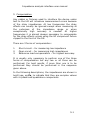
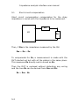
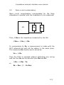
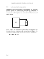
IAI
Impedance Analysis Interface
USER MANUAL
“ Do not be hasty when making measurements.”
The Impedance Analysis Interface is a precision accessory
designed for use with PSM17xx range instruments. These
instruments provide you with the tools to make a wide
variety of measurements accurately, reliably, and
efficiently - but good metrology practice must be
observed. Take time to read this manual and familiarise
yourself with the features of the instrument in order to
use it most effectively.
Impedance analysis interface user manual
IMPORTANT SAFETY INSTRUCTIONS
This equipment is designed to comply with BSEN 61010-1
(Safety requirements for electrical equipment for
measurement, control, and laboratory use) – observe the
following precautions:
• Ensure that the supply voltage agrees with the rating of
the instrument printed on the back panel before
connecting the mains cord to the supply.
• This appliance must be earthed. Ensure that the
instrument is powered from a properly grounded supply.
• High voltages can be generated if current flow to
inductive components is interrupted. Turn off the output
before connecting or disconnecting any component.
• Keep the ventilation holes on the underneath and sides
free from obstruction.
• Do not operate or store under conditions where
condensation may occur or where conducting debris
may enter the case.
• There are no user serviceable parts inside the
instrument – do not attempt to open the instrument,
refer service to the manufacturer or his appointed
agent.
Note: Newtons4th Ltd. shall not be liable for any
consequential damages, losses, costs or expenses
arising from the use or misuse of this product
however caused.
i
Impedance analysis interface user manual
DECLARATION OF CONFORMITY
Manufacturer: Newtons4th Ltd.
Address:
1 Bede Island Road
Leicester
LE2 7EA
We declare that the product:
Description:
Impedance analysis interface
Product name: IAI
Model:
conforms to the requirements of Council Directives:
89/336/EEC relating to electromagnetic compatibility:
EN 61326:1997 Class A
73/23/EEC relating to safety of laboratory equipment:
EN 61010-1
April 2005
Eur Ing Allan Winsor BSc CEng MIEE
(Director Newtons4th Ltd.)
ii
Impedance analysis interface user manual
WARRANTY
This product is guaranteed to be free from defects in
materials and workmanship for a period of 36 months from
the date of purchase.
In the unlikely event of any problem within this guarantee
period, first contact Newtons4th Ltd. or your local
representative, to give a description of the problem. Please
have as much relevant information to hand as possible.
If the problem cannot be resolved directly then you will be
given an RMA number and asked to return the unit. The
unit will be repaired or replaced at the sole discretion of
Newtons4th Ltd.
This guarantee is limited to the cost of the IAI itself and
does not extend to any consequential damage or losses
whatsoever including, but not limited to, any loss of
earnings arising from a failure of the product or software.
In the event of any problem with the instrument outside of
the guarantee period, Newtons4th Ltd. offers a full repair
and re-calibration service – contact your local
representative.
It is recommended that the IAI be re-calibrated annually
along with the measurement instrument that it is used
with.
iii
Impedance analysis interface user manual
ABOUT THIS MANUAL
The Impedance Analysis Interface from Newtons4th Ltd
(IAI) is a precision interface for use with the phase
sensitive multimeter range of test instruments, PSM1700
PsimetriQ and PSM1735 NumetriQ, for impedance analysis
applications.
This manual is concerned specifically with the IAI and its
use to measure impedance – a working knowledge is
assumed of the PSM instrument that it is used with.
Detailed descriptions of the PSM1700 PsimetriQ and
PSM1735 NumetriQ may be found in the appropriate user
manual.
Revision 1.00
This manual is copyright © 2005 Newtons4th Ltd. and all
rights are reserved. No part may be copied or reproduced
in any form without prior written consent.
1 Jun 2005
iv
Impedance analysis interface user manual
CONTENTS
1
Impedance analysis – an overview ....................... 1-1
2
Getting started ................................................. 2-1
2.1
3
Using the IAI .................................................... 3-1
3.1
3.2
4
Shunt selection ....................................................... 3-3
Selecting test conditions .......................................... 3-6
Connecting to the DUT ....................................... 4-1
4.1
4.2
4.3
4.4
5
Unpacking .............................................................. 2-1
Kelvin leads............................................................ 4-1
High frequency fixture ............................................. 4-2
Direct connection to BNC ......................................... 4-3
Custom fixtures ...................................................... 4-4
Compensation................................................... 5-1
5.1
5.2
5.3
Short circuit compensation ....................................... 5-2
Open circuit compensation ....................................... 5-3
Reference load compensation ................................... 5-4
6
Calibration ....................................................... 6-1
7
Specification ..................................................... 7-1
v
Impedance analysis interface user manual
APPENDICES
Appendix A
Accessories
Appendix B
Contact details
vi
Impedance analysis interface user manual
1 Impedance analysis – an overview
Real components are never ideal resistors, capacitors or
inductors because of unwanted parasitic effects arising
from their construction.
It is useful to model a real component as an appropriate
combination of ideal resistance, capacitance and
inductance. For example, a real inductor at a frequency
below its resonant frequency may be modelled as a pure
inductor with a series resistance; a real resistor may be
modelled either as a pure resistor with a series inductance
or by a pure resistor with a parallel capacitance; a
capacitor is most commonly modelled as a pure capacitor
with a series resistance (ESR).
The parameters of real components vary with the
conditions of frequency and voltage/current under which
they are used.
In many cases, components are used under conditions
where the parasitic effects of the component become
critical and must be measured reliably over a wide range
of operating conditions.
The impedance is analysed by measurement of the
complex impedance, Z, under controlled conditions of
frequency and voltage or current:
Z=V/I
where V is the voltage across the component
I is the current through the component
Z, V and I are complex values which may be represented
as magnitude and phase or by in-phase and quadrature
components. The LCR measurement is performed by the
PSM instrument using a discrete Fourier transform (DFT)
1-1
Impedance analysis interface user manual
at the frequency of operation. This gives the complex
impedance directly in the form of an in-phase component
and a quadrature component.
Having measured the complex impedance, Zm, in the form
of in-phase, Zr, and quadrature components, Zq, the
series and parallel models can then be computed.
Using traditional complex mathematical notation where j is
the operator √-1:
Zm = Zr + j Zq
For the series inductance model (Zq > 0):
Z = Rs + j ω Ls
and:
where ω = 2 . π . frequency
Rs = Zr
Ls = Zq / ω
For the parallel capacitance model (Zq < 0):
1/Z = 1/Rp + j ω Cp
and:
Rp = (Zr² + Zq²) / Zr
Cp = - Zq / ω . (Zr² + Zq²)
It is important to characterise the component over all the
frequencies that are relevant for a given applications. For
this reason, the IAI can be used with the phase sensitive
1-2
Impedance analysis interface user manual
multimeters from Newtons4th Ltd to sweep across a
frequency range.
1-3
Impedance analysis interface user manual
2 Getting started
The IAI is supplied with appropriate leads and accessories
for use with either the PSM1700 PsimetriQ or PSM1735
NumetriQ phase sensitive multimeters from Newtons4th
Ltd. The IAI should be calibrated with the unit that it will
be used with – see the later chapter on calibration.
2.1
Unpacking
Inside the carton there should be the following items:
one IAI unit
one appropriate mains lead
three short BNC cables
one short ribbon cable
a pair of Kelvin leads for low frequency use
this manual
There may also be a number of optional accessories if
these have been ordered with the unit.
Having verified that the entire above list of contents is
present, it would be wise to verify that your IAI operates
correctly and has not been damaged in transit.
Site the IAI under the instrument that it will be used with.
Connect the 3 short BNC cables from the BNC connectors
on the front of the IAI (OUT, CH1, and CH2) to the
corresponding BNC connectors on the PSM above it.
Connect the ribbon cable from the extension port on the
back of the IAI to that of the PSM.
Connect the red Kelvin lead to the signal+ and sense+
BNC connectors on the front of the IAI, and connect the
black Kelvin lead to the sense- and signal- BNC
2-1
Impedance analysis interface user manual
connectors. Connect the Kelvin clips across an appropriate
test component, eg. a 100nF capacitor.
Verify that the voltage ratings on the rear panels of the IAI
and the instrument are appropriate for the supply, then
connect the mains cords to the inlets on the rear panels
and the supply outlet.
Switch on the IAI and the instrument. All four leds on the
front of the IAI should illuminate. The display on the
instrument should illuminate with the model name and the
firmware version for a few seconds while it performs some
initial tests. It then normally defaults to the RMS voltmeter
display unless some other mode has been stored into the
start-up program (PROG 1).
Press the AUX key on the instrument and select fixture =
“IAI” and LCR head shunt = “normal”. Only the normal
LED should now be illuminated on the front panel of the
IAI.
If the instrument displays the message:
“FIXTURE NOT RESPONDING”
then check that the extension port cable has not been
damaged and has been correctly fitted between the
instrument and the IAI.
If the message does not appear but all 4 leds remain
illuminated then check that the IAI is correctly connected
to the supply and that the fuse is intact.
Press the OUT key on the instrument and turn on the
output.
2-2
Impedance analysis interface user manual
Press the LCR key to select the impedance analyser
function and check that the test component is measured
correctly.
In the event of any problem with this procedure, please
contact customer services at Newtons4th Ltd. or your local
authorised
representative:
contact
addresses
and
telephone numbers are given in the appendix at the back
of this manual.
2-3
Impedance analysis interface user manual
3 Using the IAI
The device under test (DUT) is measured by the IAI in a
configuration where the component is ground referenced.
This allows the IAI to be used to measure the impedance
of devices even when one terminal is connected to earth.
current
sense
CH2
OUT
DUT
CH1
The IAI has 4 selectable ‘shunts’ to sense the current
through the device under test:
‘shunt’
LOW
NORMAL
HIGH
VERY HIGH
value
5Ω
50Ω
5kΩ
500kΩ
comments
also has 1A pk buffer
not recommended above
1kHz
3-1
Impedance analysis interface user manual
When the ‘shunt’ is selected on the instrument via the AUX
menu, the resistance value is automatically entered as the
external shunt for channel 2. The ‘shunt’ may be selected
manually or the PSM can be configured to select it
automatically.
Not shown on the diagram for clarity is the 50Ω terminator
on the ‘OUT’ input connecting to the output of the PSM
instrument and the 50Ω balancing resistors on ‘CH1’ and
‘CH2’ outputs connecting to the inputs of the PSM.
For high precision measurement under some conditions it
may be necessary to compensate for parasitics within the
test connections – see the later chapter on compensation.
3-2
Impedance analysis interface user manual
3.1
Shunt selection
The different ‘shunts’ built into the IAI allow the test
conditions to be modified to optimise the measurement
accuracy. In general a higher value shunt increases the
magnitude of the current signal and decreases the
magnitude of the voltage signal; conversely a lower value
shunt decreases the magnitude of the current signal and
increases the magnitude of the voltage signal.
Optimum accuracy is when the voltage and current signals
are approximately equal (the impedance of the shunt is
approximately the same as the impedance of the DUT),
but good results can be obtained with impedances within a
factor of 100 of the shunt value.
The accuracy also depends on the frequency of operation.
For example, considering the normal shunt, used with the
PSM1735 NumetriQ, with the high frequency fixture fitted
directly to the front of the IAI, the accuracy is tabulated
below:
‘normal’ shunt accuracy table
accuracy
0.1%
1%
10%
20%
impedance range
5Ω to 500Ω
5Ω to 500Ω
500mΩ to 5kΩ
5Ω to 500Ω
500mΩ to 5kΩ
50mΩ to 50kΩ
5Ω to 500Ω
500mΩ to 5kΩ
50mΩ to 50kΩ
frequency range
10Hz to 100kHz
1Hz to 1MHz
10Hz to 100kHz
100uHz to 25MHz
1Hz to 1MHz
10Hz to 100kHz
10uHz to 35MHz
100uHz to 5MHz
10Hz to 100kHz
3-3
Impedance analysis interface user manual
It is necessary to take great care in order to achieve the
best accuracy of measurement. The leads of the
component must be scrupulously clean and for
repeatability, the component must be connected in exactly
the same position. Slight variations in connection can
result in significantly different measured values, especially
at high frequencies.
In general, the “very high” shunt should only be used for
high impedance measurements (>1MΩ) at low frequencies
(<1kHz).
The “low” shunt is used with higher current testing of low
impedances as it includes a current boosting amplifier that
can deliver up to 0.5A rms.
Warning: high voltages can be generated when the
current flowing through an inductive component is
interrupted. So turn the output off before
disconnecting an inductive or unknown component.
The “normal” and “high” shunts are general purpose and
between them cover a very wide impedance range.
shunt frequency ranges
shunt
low
normal
high
very high
impedance range
<50Ω
50mΩ to 50kΩ
5Ω to 5MΩ
>1MΩ
frequency range
<10MHz
all
all
<1kHz
Of course, this table is only a guide and each ‘shunt’ can
be used beyond the limits quoted.
3-4
Impedance analysis interface user manual
If automatic shunt selection is configured on the
instrument
then
the
appropriate
shunt
will
be
automatically selected according to the test conditions and
the measured impedance.
3-5
Impedance analysis interface user manual
3.2
Selecting test conditions
The frequency and voltage of the generator are selected
on the PSM instrument. The actual voltage across the DUT
depends on the impedance of the component at the test
frequency and the impedance of the selected shunt.
If the generator output is set as a peak voltage Vpk, then
because of the 50Ω impedances the rms voltage across the
series combination of shunt and DUT may be
approximated as Vpk/2√2 with a series resistance of 25Ω.
Then the voltage seen by the DUT, Vdut, will be
approximately given by:
Vdut ~= Vpk/2√2 x Zdut/(Zdut + Rshunt + 25)
where: Zdut = impedance of the DUT
Rshunt = resistance of the ‘shunt’
The PSM instrument clearly displays the measured voltage
across the DUT and the measured current through it.
To fix the test voltage at a specified level, enable ac trim
on CH1 using the TRIM menu on the instrument and set
the desired rms level for Vdut. The instrument will then
adjust the generator output level until the measured
voltage across the component is as specified.
Note that the low shunt also has a high speed buffer so the
25Ω term does not appear, and the equation becomes:
Vdut ~= Vpk/2√2 x Zdut/(Zdut + 5)
The maximum rms current, Imax, in this case into a short
circuit becomes:
Imax ~= 10/2√2 / 5
3-6
Impedance analysis interface user manual
~= 0.7A rms
The optimum test conditions to use depend on the
component or DUT and the application as many
components change their characteristics with frequency
and test voltage. The PSM instrument can automatically
select test conditions or they can be entered manually.
DC offsets can also be added to the test voltage where
needed, for example testing electrolytic capacitors which
need a bias voltage. In this case, it may be best to set the
PSM instrument to AC coupling which will increase the
measured accuracy in cases where the AC signal is small
relative to the DC level.
3-7
Impedance analysis interface user manual
4 Connecting to the DUT
4.1
Kelvin leads
The IAI is supplied with a pair of Kelvin leads for low
frequency use (<5MHz) which make simple connections to
a discrete component.
The red lead should be connected to the BNC connectors
marked SIGNAL+ and SENSE+ on the front of the IAI; the
black lead should be connected to the BNC connectors
marked SIGNAL- and SENSE-.
The Kelvin clips can then be clipped onto the body of the
component, as close as possible to the component.
For accurate measurements it is essential that the
component leads are clean. For repeatability of
measurements, it is important to connect the Kelvin clips
in the same physical arrangement when testing different
components.
signal+
IAI
sense+
DUT
sensesignal-
4-1
Impedance analysis interface user manual
4.2
High frequency fixture
For testing components over all frequencies, there is a
dedicated test fixture available as an accessory from
Newtons4th Ltd. This can clip directly onto the front of the
IAI by means of four BNC to BNC couplers supplied with it
to minimise effects due to cabling.
Connection is made to the component by four gold plated
contact areas in a four-wire Kelvin arrangement; SIGNAL+
and SIGNAL- appear on the lower pair of contacts,
SENSE+ and SENSE- are picked up from the upper pair of
contacts.
The lower pair of contacts are secured to the connectors
attached to the IAI and does not move; the upper pair of
contacts can be lifted by light finger pressure. The contacts
are pressed closed by springs.
To insert a component push up the upper contact plate so
that the legs of the component can be inserted. If
necessary push up the upper contact plate on one side first
and then the other side so that the component can be
pushed home. For high frequency work it is essential for
the component to be inserted as far as possible.
The HF fixture does not have to be clipped to the front of
the IAI but can be used with some short BNC leads instead
of the BNC couplers.
4-2
Impedance analysis interface user manual
4.3
Direct connection to BNC
Because the DUT is ground referenced by the IAI (SIGNALis connected to earth), the IAI can be used to directly
measure the input and output impedances of equipment
which is earthed eg. oscilloscope inputs.
The easiest way to make the connections is to use the BNC
connection kit available as an accessory, consisting of:
Dual BNC adaptor
BNC lead
BNC splitter lead
Ensure that there are no harmful voltages present
on the BNC connector to be tested.
Connect the ‘dual BNC adaptor’ to the BNC terminal which
is to be measured. Connect the ‘BNC lead’ from one end of
the adaptor to the SIGNAL+ terminal of the IAI. Connect
the single BNC end of the ‘BNC splitter lead’ to the other
end of the adaptor; connect the BNC with the red boot to
the SENSE+ terminal of the IAI; connect the BNC with the
black boot to the SENSE- terminal. The SIGNAL- terminal
is not used in this configuration.
signal+
IAI
sense+
DUT
sensesignal-
4-3
Impedance analysis interface user manual
4.4
Custom fixtures
For dedicated test facilities, the IAI can be used with
custom made fixtures.
The test voltage is provided at the SIGNAL+ terminal, and
the selected internal current sense circuitry measures the
current that is drawn from this terminal. The voltage
across the DUT should be presented to the high impedance
SENSE+ and SENSE- terminals. The SIGNAL- terminal is
not used in this configuration.
For remote operation at a distance from the IAI, the
fixture could have active buffers to drive the SENSE+ and
SENSE- cables to isolate the effects of the cabling from the
DUT. Use high impedance amplifiers (eg JFET input types),
in x2 mode with the characteristic resistance for the cable
being used (usually 50Ω), and terminate the cables at the
IAI with the same value.
The AUX connector on the IAI provides +/-12V at up to
50mA per rail for powering active fixtures. The outputs are
current limited with self resetting fuses. Local smoothing
capacitors and possibly voltage regulators are advisable on
the custom fixture.
The AUX connector is a 3.5mm stereo jack socket with the
following pinout:
barrel
middle
tip
4-4
0V
-12V
+12V
Impedance analysis interface user manual
5 Compensation
Any cables or fixtures used to interface the device under
test to the IAI will introduce measurement errors because
of the stray impedances. At low frequencies the stray
effects can usually be ignored except when measuring at
the extremes of the impedance range or when
exceptionally high accuracy is needed. At higher
frequencies it is almost always necessary to compensate
for the stray effects unless using the HF component fixture
clipped to the front of the IAI.
There are 3 forms of compensation:
1.
2.
3.
Short circuit – for measuring low impedance
Open circuit – for measuring high impedances
Reference load compensation – for highest accuracy.
It is usually only necessary to perform one of the three
forms of compensation but any two or all three can be
performed. For best results, if more than one is to be
performed they should be performed in the sequence
given above.
In the following descriptions, the impedances are shown in
bold type, eg Zx, to indicate that they are complex values
with in-phase and quadrature components.
5-1
Impedance analysis interface user manual
5.1
Short circuit compensation
Short circuit compensation compensates for the stray
impedance in series with the impedance to be measured:
Zs
IAI
Zx
Then, if Zm is the impedance measured by the IAI:
Zm = Zs + Zx
To compensate for Zs, a measurement is made with the
DUT shorted out but with all the cables in the same place.
This measures Zs directly and is stored as Zs.
Then the DUT is replaced without disturbing any wiring
and the true Zx can be derived from Zm and Zs:
Zx = Zm - Zs
5-2
Impedance analysis interface user manual
5.2
Open circuit compensation
Open circuit compensation compensates for the stray
impedance in parallel with the impedance to be measured:
IAI
Zo
Zx
Then, if Zm is the impedance measured by the IAI:
1/Zm = 1/Zo + 1/Zx
To compensate for Zo, a measurement is made with the
DUT removed but with all the cables in the same place.
This measures Zo directly and is stored as:
Yo = 1/Zo
Then the DUT is replaced without disturbing any wiring
and the true Zx can be derived from Zm and Yo:
or:
1/Zx = 1/Zm - Yo
Zx = Zm / (1 – Yo.Zm)
5-3
Impedance analysis interface user manual
5.3
Reference load compensation
Reference load compensation compensates for complex
effects within the cabling and fixtures by measuring a
known reference component. The value of the reference
component and its phase are entered and the measured
value stored.
IAI
Zr
Then, if Zl is the impedance measured by the IAI with the
known reference impedance Zr connected and Zm is the
impedance measured by the IAI with the DUT connected:
Zx = Zm . Zr / Zl
5-4
Impedance analysis interface user manual
6 Calibration
For optimum accuracy, the IAI should be re-calibrated
annually with the instrument that it is used with. The
calibration values are stored in the instrument so the IAI
and PSM instrument should be kept together as a pair.
The calibration process is similar to compensation except
that it is performed over a series of frequencies. The
reference components used for the calibration are resistors
of the same value as the internal current sense shunts.
The calibration procedure is controlled by a script file,
running under CommVIEW, which instructs the operator to
fit the appropriate fixture then sends the necessary
commands to the instrument.
The calibration fixture set comprises:
4
1
1
4
1
BNC to BNC couplers
or more short circuit fixtures
or more open circuit fixtures
reference fixtures
script file to run under CommVIEW.
The calibration process stores the measured value for Zs,
Yo, and Zl for each frequency point, and Zr.
Then, if Zm is the impedance measured by the IAI:
Zx = Zr . (1 – (Zl – Zs).Yo) (Zm – Zs)
(1 – (Zm – Zs).Yo) (Zl – Zs)
Interpolation is used to determine the constants for
frequencies between calibration points
6-1
Impedance analysis interface user manual
7 Specification
All these specifications are quoted for the system
consisting of IAI with HF fixture and PSM17xx NumetriQ
unless otherwise stated.
System
PSM1700
PSM1735
Frequency range
10uHz – 1MHz
10uHz – 35MHz
Basic accuracy
0.25%
0.1%
Impedance range
10mΩ – 100MΩ
10pF – 1000uF
100nH – 10kH
Excitation voltage
5Vpk max
Excitation control
voltage or current
Configuration
ground referenced
DC offset voltage
+/- 5V max
Parameters measured
R, L, C, Z, phase, QF, tan(δ)
series or parallel circuit
selectable shunts
4
buffer current (low
0.5A rms max
shunt)
connectors
power requirements
size
weight
temperature range
IAI only
grounded BNC
universal input
90-264V rms, 47-63Hz
15VA max.
60H x 350W x 250D mm approx
2kg approx
5 to 35˚C
7-1
Impedance analysis interface user manual
For each shunt, the accuracy of measurement depends on
the impedance and the frequency.
‘normal’ shunt accuracy table
accuracy
0.1%
1%
10%
20%
Phase
Accuracy
impedance range
5Ω to 500Ω
5Ω to 500Ω
500mΩ to 5kΩ
5Ω to 500Ω
500mΩ to 5kΩ
50mΩ to 50kΩ
5Ω to 500Ω
500mΩ to 5kΩ
50mΩ to 50kΩ
frequency range
10Hz to 100kHz
1Hz to 1MHz
10Hz to 100kHz
100uHz to 25MHz
1Hz to 1MHz
10Hz to 100kHz
10uHz to 35MHz
100uHz to 5MHz
1Hz to 500kHz
0.05⁰+ 0.005⁰ / kHz
‘high’ shunt accuracy table
accuracy
0.1%
1%
10%
20%
Phase
Accuracy
7-2
impedance range
500Ω to 50kΩ
500Ω to 50kΩ
50Ω to 500kΩ
500Ω to 50kΩ
50Ω to 500kΩ
5Ω to 5MΩ
500Ω to 50kΩ
50Ω to 500kΩ
5Ω to 5MΩ
frequency range
10Hz to 100kHz
1Hz to 1MHz
10Hz to 100kHz
100uHz to 15MHz
1Hz to 1MHz
10Hz to 100kHz
10uHz to 35MHz
100uHz to 5MHz
1Hz to 500kHz
0.05⁰+ 0.005⁰ / kHz
Impedance analysis interface user manual
‘low’ shunt accuracy table
accuracy
0.1%
1%
10%
Phase
Accuracy
impedance range
500mΩ to 50Ω
500mΩ to 50Ω
50mΩ to 500Ω
500mΩ to 50Ω
50mΩ to 500Ω
10mΩ to 5kΩ
frequency range
10Hz to 100kHz
1Hz to 1MHz
10Hz to 100kHz
100uHz to 10MHz
1Hz to 1MHz
10Hz to 100kHz
0.1⁰+ 0.01⁰ / kHz
‘very high’ shunt accuracy table
accuracy
0.1%
1%
10%
Phase
Accuracy
7-4
impedance range
50kΩ to 5MΩ
50kΩ to 5MΩ
5kΩ to 50MΩ
50kΩ to 5MΩ
5kΩ to 50MΩ
500Ω to 100MΩ
frequency range
10Hz to 1kHz
1Hz to 1kHz
10Hz to 1kHz
100uHz to 1kHz
1Hz to 1kHz
10Hz to 1kHz
0.1⁰+ 0.05⁰ / kHz
Impedance analysis interface user manual
Appendix A – Accessories
ACCESSORIES
A-1
Impedance analysis interface user manual
High frequency component fixture
The high frequency component fixture clips onto the front
of the IAI with four BNC coupling adaptors (supplied) for
easy testing of components.
Part numbers
500-066
A-2
HF impedance fixture
Impedance analysis interface user manual
BNC connection adaptor
The IAI can be used to directly measure the impedance of
inputs and outputs of other equipment even if the BNC
connector is grounded.
The BNC connection kit consists of :
Dual BNC adaptor
BNC lead
BNC splitter lead
Part numbers
500-067
BNC connection adaptor
A-3
Impedance analysis interface user manual
Calibration kit
The IAI is calibrated with the instrument that it is used
with, by means of a series of calibration fixtures. Open
circuit, short and circuit and reference load calibration is
performed for each shunt and the values stored in the
non-volatile FLASH memory of the instrument.
The calibration kit includes all the necessary fixtures, four
BNC coupling adaptors to fit them to the front of the IAI
and a disc with the script file to run under CommVIEW.
Part numbers
500-072
A-4
IAI calibration kit
Appendix B – Contact details
Please direct all queries or comments regarding the
PsimetriQ instrument or manual to:
Newtons4th Ltd.
1 Bede Island Road
Leicester
LE2 7EA
United Kingdom
Tel: (0116) 230 1066
Fax: (0116) 230 1061
international
international
+44 116 230 1066
+44 116 230 1061
E-mail address:
[email protected]
[email protected]
web site:
www.newtons4th.com
At Newtons4th Ltd. we have a policy of continuous product
improvement and are always keen to hear comments,
whether favourable or unfavourable, from users of our
products.