1
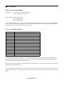
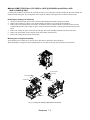
! Dynamic Braking Connections
"General
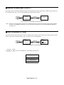
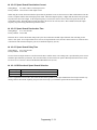
Dynamic braking (DB) enables the motor to be brought to a smooth and rapid stop. This is achieved by dissipating the
regenerative energy of the AC motor across the resistive components of the Dynamic Braking option. For further details on
dynamic braking operation, see the instruction sheet shipped with dynamic braking components.
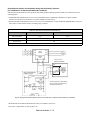
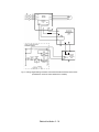
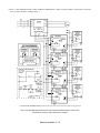
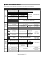
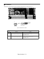
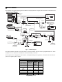
Drives P7U20P4 thru P7U2018 and P7U40P4 thru P7U4018 have an integral braking transistor and require the addition of a
Remote Mounted Resistor Unit or a Heat Sink Mount Resistor (ERF). All higher rated Drives require the use of a Braking
Transistor Unit (CDBR) and a Remote Mount Resistor Unit.
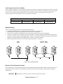
Remote Mount Resistor Units typically mount outside of the electrical enclosure. Braking Transistor Units mount inside of the
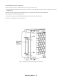
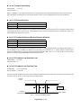
electrical enclosure. Heat Sink Mount Resistors mount to the back of the Drive, attaching directly to the heat sink.
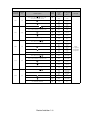
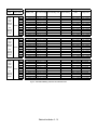
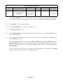
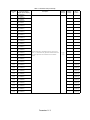
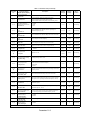
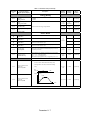
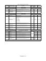
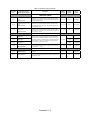
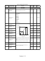
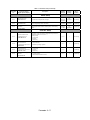
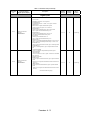
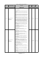
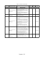
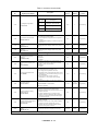
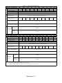
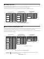
Table 2.7 Heat Sink Mount Dynamic Braking Resistor - 3% Duty Cycle
Drive
Rated
Input
Vac
208-240
480
Heat Sink Mount Resistor
Part No.
Qty.
Reqd.
Resistance
(Ohms)
Power
(Watts)
Approx.
Braking
Torque
(%)
20P4
R7505
1
200
150
20P7
R7505
1
200
21P5
R7504
1
22P2
R7503
23P7
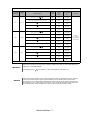
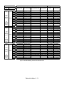
Drive
Model No.
P7U
Dimensions (Inches)
Height
Width
Depth
220
7.16
1.73
0.51
150
125
7.16
1.73
0.51
100
150
125
7.16
1.73
0.51
1
70
150
120
7.16
1.73
0.51
R7510
1
62
150
100
7.16
1.73
0.51
40P4
R7508
1
750
150
230
7.16
1.73
0.51
40P7
R7508
1
750
150
130
7.16
1.73
0.51
41P5
R7507
1
400
150
125
7.16
1.73
0.51
42P2
R7506
1
115
150
115
7.16
1.73
0.51
43P7
R7505
1
200
150
110
7.16
1.73
0.51
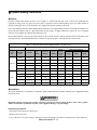
"Installation
This option should only be installed by a technically qualified individual who is familiar with this type of equipment and the
hazards involved.
WARNING
Hazardous voltages can cause severe injury or death. Lock all power sources feeding the Drive in the “OFF” position.
Failure to follow these installation steps may cause equipment damage or personal injury.
Preliminary Procedures
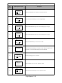
1. Disconnect all electrical power to the Drive.
2. Remove Drive front cover.
3. Use a voltmeter to verify that voltage is disconnected from incoming power terminals and that the DC bus has dissipated.
Electrical Installation 2 - 12