1
Coprocessor Modules
2
GFK-0164G
August 1997
Programmable Coprocessor Module
Installation
Expansion Memory
• Installation should not be attempted without referring to the applicable Programmable Controller
Installation Manual (see reference 5).
The PCM can operate with or without an expansion
memory daughter board. The base memory on the
PCM board has up to 95 Kbytes user memory. The expansion memory daughter board permits expansion of
program/data memory by 64, 128, 256 or 512 Kbytes.
The battery which supports this memory is located on
the base board housing as shown in figure 2.
• Make sure rack power is off.
• Install expansion memory if required.
• Connect the battery to either of the battery connectors on the module. (See figure 2)
• Install in the rack. (See figure 1)
• Turn on power.
The module should power up and blink the top LED.
When the diagnostics have completed successfully the
top LED stays on.
PARALLEL
a42786g
ÎÎ
ÎÎ
Î
ÎÎ
Î
ÎÎ
Î
ÎÎ
Î
ÎÎ
ÎÎÎÎ
ÎÎ
ÎÎ
Î
ÎÎ
Î
ÎÎ
Î
ÎÎ
Î
ÎÎ
ÎÎÎÎ
Î
Î
ÎÎ
ÎÎ
Î
ÎÎ
Î
ÎÎ
Î
ÎÎ
Î
ÎÎ
ÎÎÎÎ
Î
Î
Î
Î
ÎÎÎÎÎÎ
ÎÎÎ
ÎÎÎ
ÎÎÎ
Î ÎÎÎÎÎÎÎÎ
Î
Î
ÎÎÎÎÎÎÎÎ
ÎÎ
ÎÎ
Î
ÎÎ
Î
ÎÎ
É
ÎÎ
Î
ÎÎ
ÎÎ
ÎÎ
Î
ÎÎ
ÎÎ
ÎÎÎ
ÎÎ
ÎÎÎ
ÎÎ
ÉÎÎ
ÎÎ
Î
ÎÎ
ÎÎ
ÎÎ
Î
ÎÎ
ÎÎ
Î
Î
É
Î
ÎÎ
ÎÎ
ÎÎ
Î
Î
Î
ÎÎ
ÎÎ
Î
ÎÎ
Î
ÎÎ
É
ÎÎ
Î
ÎÎ
ÎÎ
ÎÎ
Î
ÎÎÎÎÎÎ
ÎÎÎ
ÎÎÎ
ÉÎÎ
Î
ÎÎ
ÎÎ
Î
ÎÎ
Î
ÎÎ
Î
ÎÎ
Î
ÎÎ
ÎÎÎÎÎÎÎÎÎÎÎÎÎ
ÎÎÎ
Î
Î
ÎÎ
ÎÎ
Î
ÎÎ
Î
ÎÎ
Î
ÎÎ
Î
ÎÎ
Î
Î
Î
ÎÎ
ÎÎ
Î
ÎÎ
Î
ÎÎ
Î
ÎÎ
Î
ÎÎ
ÎÎÎÎÎÎ
ÎÎÎ
ÎÎÎ
ÎÎÎ
Î
ÎÎ
ÎÎ
Î
ÎÎ
Î
ÎÎ
Î
ÎÎ
Î
ÎÎ
ÎÎ
ÎÎ
Î
ÎÎ
ÎÎ
ÎÎ
Î
ÎÎÎ
ÎÎÎ
ÎÎÎ
ÎÎÎ
ÎÎ
Î
Î ÎÎ
ÎÎ
ÎÎ
Î
ÎÎ
Î
ÎÎ
Î
Î
ÎÎ
ÎÎ
ÎÎ
Î
Î
Î
Î
ÎÎ
ÎÎ
Î
ÎÎ
Î
ÎÎ
Î
ÎÎ
Î
ÎÎ
ÎÎ
ÎÎ
Î
ÎÎÎÎÎÎ
ÎÎÎ
ÎÎÎ
ÎÎÎ
Î
RACK 0
P
S
C B
P T
U M
a42759
PROGRAMMER
G
B
C
or
N
B
C
ONE
METER
IC66* I/O BUS (7500 FEET (2285 METERS) MAXIMUM)
OPEN
REPLACEMENT
BATTERY
CONNECTOR
CURRENTLY
INSTALLED
BATTERY
CONNECTOR
INSTALL NEW
BATTERY BEFORE
UNPLUGGING OLD
BATTERY. USE
IC697ACC701
RACK 6
NOTE
EXPANSION
MEMORY
BOARD
IC697MEM713
IC697MEM715
IC697MEM717
IC697MEM719
OPTIONAL MEMORY
USE IC697MEM71
RACK 7
PORT 2
B
R
M
CPU BRM BTM GBC/NBC PCM PS -
SELECTED CPU MODEL
BUS RECEIVER MODULE, BEM711
BUS TRANSMITTER MODULE, BEM713
BUS CONTROLLER, BEM731/734
PROGRAMMABLE COPROCESSOR MODULE, PCM711
POWER SUPPLY, PWR710/711/724/748
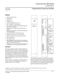
Figure 1. Typical PLC System Configuration (PCM
Shown in Rack 1)
RS–232 OR
RS–422/485
COMPATIBLE
PROGRAMMABLE
COPROCESSOR,
COMMUNICATIONS
RS–232 OR
RS–422/485
COMPATIBLE
MODULE
IC697PCM711
LABEL
44A726758–203
I/O TERMINATOR
(LAST RACK)
LEGEND
PORT 1
MODULE FUNCTION
IC66* I/O BUS (7500 FEET (2285 METERS) MAXIMUM)
ONE
METER
P
S
TOTAL LENGTH OF ALL INTERCONNECTING
CABLES FROM BTM TO LAST BRM IS 50 FEET
(15 METERS) MAXIMUM. ALL RACKS MUST BE
AT SAME GROUND POTENTIAL
(8 RACKS MAXIMUM).
USER 2
ON = OK, ACTIVE
OR USER
BATTERY
CONNECTIONS
IC66*
I/O BLOCK
G
B
C
or
N
B
C
MODULE OK
PUSH TO RESTART
APPLICATION.
PUSH AND HOLD TO
STOP AND RESET.
P
C
M
B
R
M
PCM 711
USER 1
RACK 1
B
R
M
ÎÎ
ÎÎ
Î
ÎÎÎ
ÎÎ
Î
ÎÎ
ÎÎ
Î
ÎÎ
Î
ÎÎ
Î
ÎÎ
ÎÎ
Î
ÎÎ
Î
Î
ÎÎ
ÎÎÎ
Î
Î
ÎÎ
Î
ÎÎ
Î
ÎÎ
Î
ÎÎ
Î
ÎÎ
Î
ÎÎ
Î
ÎÎ
Î
ÎÎ
Î
ÎÎ
Î
ÎÎ
Î
ÎÎ
Î
ÎÎ
Î
ÎÎ
Î
ÎÎ
Î
ÎÎ
Î
Î
ÎÎ
Î Î
ÎÎ
Î
PCM 711
Figure 2. Programmable Coprocessor Module - User
Details