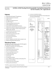
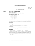
1
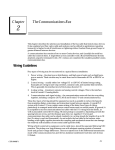
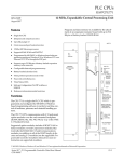
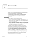
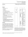
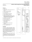
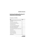
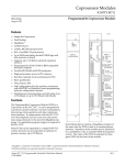
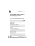
This Datasheet for the
IC697BEM731
Series 90-70 Genius I/O Bus Controller.
http://www.qualitrol.com/shop/p-14755-ic697bem731.aspx
Provides the wiring diagrams and installation guidelines for this GE Series 90-30
module.
For further information, please contact Qualitrol Technical Support at
1-800-784-9385
[email protected]
1
Bus Expansion Modules
IC697BEM731/734
61
Bus Controller Module
GFK-0165G
August 1997
Bus Expansion Modules
Bus Controller Module (IC697BEM731/734)
datasheet GFK-0165G
Features
D
D
D
D
D
D
D
D
a44715
ÎÎÎÎ
ÎÎÎÎÎÎÎÎ ÎÎ
ÎÎÎÎ
ÎÎ
ÎÎ
ÎÎ
ÎÎ
ÎÎÎÎ
ÎÎ
ÎÎ
ÎÎ
ÎÎÎÎ
ÎÎ
ÎÎ
ÎÎÎÎ
ÎÎ
ÎÎ
ÎÎ
Î
ÎÎÎÎ
ÎÎ
ÎÎ
ÎÎÎÎÎ
ÎÎÎÎ
ÎÎ
Î
ÎÎÎÎ
ÎÎ
ÎÎ
ÎÎÎÎ
ÎÎ
ÎÎ
ÎÎÎÎ
ÎÎ
ÎÎ
ÎÎÎÎ
ÎÎ
ÎÎ
ÎÎÎÎ
ÎÎ
ÎÎ
ÎÎÎÎ
ÎÎ
ÎÎ
ÎÎÎÎ
ÎÎ
ÎÎ
ÎÎÎÎÎÎ
ÎÎ
ÎÎÎÎ
ÎÎ
ÎÎ
ÎÎÎÎ
ÎÎ
ÎÎ
ÎÎÎÎ
ÎÎ
ÎÎ
ÎÎÎÎ
ÎÎ
ÎÎ
ÏÏÏÏ
ÎÎÎÎÎÎ
ÎÎ
ÎÎÎÎ
ÎÎ
ÎÎ
ÎÎÎÎ
ÎÎ
ÎÎ
ÎÎÎÎ
ÎÎÎ ÎÎ
ÎÎÎÎ
ÎÎ
ÎÎ
Î
ÎÎÎÎ
ÎÎ
Thirty Drops per channel
IC66* (IC660 or IC661) I/O Diagnostics
OK
CH 1 OK
Redundant blocks, cables and CPUs supported
Global Communications
Hand Held Monitor Port
IC66* LAN Communications
BEM 731
BUS CONTROLLER
1 CHANNEL
MODULE OK
CHANNEL 1 OK
Soft configuration by CPU
NOT USED
ON = OK
Operation augmented by IC697 PLC Alarm Processor function
HAND HELD
MONITOR
CHANNEL 1
Functions
MODULE FUNCTION
The IC66* Bus Controller (GBC/NBC) is available as a
single channel controller. It occupies a single IC66*
PLC slot. The bus controller is configured by the MSDOS r or Windowsr programming software configurator function. IC66* Input/Output blocks are
scanned asynchronously by the bus controller and I/O
data is transferred to the CPU once per scan over the
backplane of the IC697 PLC rack.
BUS
CONTROLLER
( 1 CHANNEL )
Removal of terminal
block breaks bus if
external jumpers are
not applied as shown
CHANNEL 1
SER 1
The bus controller also supports directed communications initiated by a PLC CPU Communication Service
Request. In addition, it may be configured to perform
global communications.
Faults reported by the bus controller are managed by
the PLC Alarm Processor Function which time stamps
and queues faults in a table.
For applications requiring peer to peer information
transfer, the Bus Controller can serve as a communications node linking other devices (Bus Controllers,
PCIMs, and other IC66* devices) via the IC66* bus.
Such a network can provide communications between multiple PLCs and host computers.
These communications include transmitting global
data from one CPU to another. The global data area is
identified by MS-DOS or Windows configuration.
After initialization, the specified data area is transferred between devices automatically and repetitively.
SER 1
SER 2
SER 2
SHIELD
OUT
SHIELD
IN
NC
NC
NC
NC
NC
NC
MODULE
IC697BEM731C
LABEL
44A726758-11
In addition, messages called Datagrams can be transmitted in response to individual commands in the ladder logic. Datagrams can be sent from one device on
the network to another, or broadcast to all devices on
the bus. IC66* LAN communications are supported
throughout the IC69* PLC family.
r MS-DOS and Windows are registered trademarks of Microsoft Corporation.
t
Series 90 -70 Programmable Controller Data Sheet Manual
GFK-0600F
61-1
Bus Expansion Modules
2
GFK-0165G
August 1997
Bus Controller Module
Installation
a42985
ÎÎ
Î
ÎÎ
ÎÎ
Î
ÎÎ ÎÎ
ÎÎ
Î
ÎÎÎ
ÎÎ
Î
ÎÎ
Î
Î
Î
ÎÎ
ÎÎ
Î
ÎÎ
Î
ÎÎ
Î
ÎÎ
Î
ÎÎ
Î
ÎÎ
Î
ÎÎ
Î
ÎÎ
Î
ÎÎ
Î
ÎÎ
Î
ÎÎ
Î
ÎÎ
Î
ÎÎ
Î
ÎÎ
Î
ÏÏÏÏ
ÎÎ
Î
ÎÎ
Î
ÎÎ
Î
ÎÎ
Î
Î
ÎÎ
Î
Î
D Installation should not be attempted without referring to the applicable PLC Installation Manual.
D Make sure rack power is off.
D Install in rack. (See figure 1)
D Turn on power.
The module should power up and blink the top LED
for about 5 seconds. When the diagnostics have completed successfully the top LED stays. The middle
LED is turned ON when a valid configuration for the
module has been received from the CPU, and the
IC66* I/O bus operation has been verified. The bottom LED is OFF under all conditions.
ÎÎ
ÎÎ
Î
ÎÎ
Î
ÎÎ
ÎÎ
Î
ÎÎ
Î
ÎÎ
ÎÎ
Î
ÎÎ
Î
ÎÎ
ÎÎ
Î
ÎÎ
Î
ÎÎÎÎ
ÎÎ
ÎÎ
Î
ÎÎ
Î
ÎÎ
ÎÎ
Î
ÎÎ
Î
ÎÎÎÎ
Î
Î
ÎÎ
ÎÎ
Î
ÎÎ
Î
ÎÎ
ÎÎ
Î
ÎÎ
Î
ÎÎÎÎ
ÎÎÎÎÎÎÎÎ
Î
ÎÎ
ÎÎÎÎÎÎ
ÎÎÎ
ÎÎÎÎÎ
ÎÎÎÎÎÎÎÎÎÎ
ÎÎÎÎÎÎÎÎ
ÎÎ
ÎÎ
ÎÎÎ
ÎÎ
ÎÎÎ
ÎÎ
ÎÎ
Î
ÎÎ
Î
ÎÎ
ÎÎ
ÎÎ
ÎÎ
ÎÎ
Î
Î
ÎÎ
Î
ÎÎ
Î
ÎÎ
ÎÎ
ÎÎ
ÎÎ
ÎÎ
Î
ÎÎ
Î
ÎÎ
ÎÎ
Î
ÎÎ
ÎÎ
ÎÎ
ÎÎ
Î
Î
ÎÎ
ÎÎ
Î
ÎÎ
Î
ÎÎ
ÎÎ
Î
ÎÎ
Î
ÎÎ
ÎÎ
ÎÎ
ÎÎÎÎÎÎ
ÎÎÎ
ÎÎÎÎÎ
ÎÎ
ÎÎÎÎÎÎ
ÎÎÎ
ÎÎÎÎÎ
ÎÎ
ÎÎ
ÎÎ
Î
ÎÎ
Î
ÎÎ
ÎÎ
Î
ÎÎ
Î
Î
Î
ÎÎ
ÎÎ
Î
ÎÎ
Î
ÎÎ
ÎÎ
Î
ÎÎ
Î
Î
Î
Î
ÎÎ
ÎÎ
Î
ÎÎ
Î
ÎÎ
ÎÎ
Î
ÎÎ
Î
ÎÎÎÎÎÎ
ÎÎÎ
ÎÎÎÎÎ
ÎÎ
ÎÎÎÎ
ÎÎÎ
ÎÎÎ
ÎÎÎ
ÎÎÎ
ÎÎ ÎÎÎÎ ÎÎ
ÎÎ
Î
ÎÎ
Î
ÎÎ
Î
ÎÎ
Î
ÎÎ
Î
ÎÎ
Î
ÎÎ
ÎÎ
ÎÎ
ÎÎ
Î
ÎÎ
Î
ÎÎ
Î
ÎÎ
Î
ÎÎ
Î
ÎÎ
ÎÎ
ÎÎ
ÎÎ
Î
Î
ÎÎ
ÎÎ
Î
ÎÎ
Î
ÎÎ
ÎÎ
Î
ÎÎ
Î
ÎÎ
ÎÎ
ÎÎ
ÎÎÎÎÎÎ
ÎÎÎ
ÎÎÎÎÎ
ÎÎ
PARALLEL
C B
P T
U M
CHANNEL 1 OK
NOT USED
ON = OK
HAND HELD
MONITOR
CHANNEL 1
MODULE FUNCTION
BUS
a42786g
RACK 0
P
S
BEM 731
MODULE OK
CONTROLLER
( 1 CHANNEL )
PROGRAMMER
G
B
C
or
N
B
C
ONE
METER
Removal of terminal
block breaks bus if
external jumpers are
not applied as shown
CHANNEL 1
SER 1
IC66* I/O BUS (7500 FEET (2285 METERS) MAXIMUM)
RACK 1
B
R
M
P
C
M
IC66*
I/O BLOCK
RACK 6
G
B
C
or
N
B
C
TOTAL LENGTH OF ALL INTERCONNECTING
CABLES FROM BTM TO LAST BRM IS 50 FEET
(15 METERS) MAXIMUM. ALL RACKS MUST
BE AT SAME GROUND POTENTIAL
(8 RACKS MAXIMUM).
B
R
M
CPU
BRM
BTM
GBC/NBC
PCM
PS
-
SELECTED CPU MODULE
BUS RECEIVER MODULE, BEM711
BUS TRANSMITTER MODULE, BEM713
BUS CONTROLLER, BEM731/734
PROGRAMMABLE COPROCESSOR MODULE, PCM711
POWER SUPPLY, PWR710/711/724/748
Figure 1. Typical PLC System Configuration
61-2
NC
NC
NC
NC
NC
NC
RACK 7
Figure 2. IC66 * Bus Controller Module User Details
Note
I/O TERMINATOR
(LAST RACK)
LEGEND
SER 2
SHIELD
IN
IC66* I/O BUS (7500 FEET
(2285 METERS) MAXIMUM)
ONE
METER
P
S
SER 2
SHIELD
OUT
MODULE
IC697BEM731C
LABEL
44A726758-11
NOTE
B
R
M
SER 1
Refer to Figure 1, Bus Transmitter Module
version IC697BEM713A must be installed to
the right of the GBC/NBC or any other
IC697 I/O modules.
BTM version
IC697BEM713B can be installed as shown in
the figure (next to the CPU).
t
Series 90 -70 Programmable Controller Data Sheet Manual
GFK-0600F
Bus Expansion Modules
3
GFK-0165G
August 1997
Bus Controller Module
Removing a Module
The instructions below should be followed when removing a module from its slot in a rack.
D Grasp the board firmly at the top and bottom of
the board cover with your thumbs on the front of
the cover and your fingers on the plastic clips on
the back of the cover.
D Updates all outputs on the I/O blocks.
D Sends any command received from the CPU (for
example, Clear Circuit Fault) to the appropriate
device.
The IC66* I/O bus scan is independent of the IC697
PLC CPU sweep. The PLC CPU sweep is shown below.
D Squeeze the rack clips on the back of the cover
a42189
with your fingers to disengage the clip from the
rack rail and pull the board firmly to remove it
from the backplane connector.
BUS CONTROLLER
D Slide the board along the card guide and remove it
from the rack.
BUS
TOKEN
IN
INPUTS
AND
DIAGNOSTICS
Each IC66* I/O serial bus conveys data by passing a
”token” among the devices on the bus.
a43528
TOKEN PATH
ÎÎ
ÎÎ
(DEVICE 31)
1
2
UPDATE
INPUTS
LADDER
LOGIC
Bus Controller Operation
BUS
CONTROLLER
CPU SWEEP
3
BUS
TOKEN
OUT
OUTPUTS
AND
COMMANDS
SEND
OUTPUTS
PROGRAMMER
COMMUNICATIONS
WINDOW
MESSAGES
SYSTEM
COMMUNICATIONS
WINDOW
30
Figure 4. CPU Sweep
Figure 3. Bus Scan Cycle
During the bus scan, the Bus Controller:
D Receives all inputs from the I/O blocks.
D Receives any faults and sets diagnostic status references for use of the PLC CPU when it is accessed
once each scan.
t
Series 90 -70 Programmable Controller Data Sheet Manual
GFK-0600F
During the I/O service portions of the CPU sweep, the
Bus Controller:
D Makes available to the CPU all discrete inputs and
analog inputs.
D Receives current outputs and new commands
from the CPU.
D Reports its status and that of the serial bus.
61-3
Bus Expansion Modules
4
GFK-0165G
August 1997
Bus Controller Module
Communications Window
The Bus Controller can communicate with the CPU
via the Communications window using these commands:
1
Pulse Test Outputs
2
ReadConfiguration
3
WriteConfiguration
4
ReadDiagnostics
5
Clear Circuit Fault
6
Clear All Circuit Faults
7
AssignMonitor
8
Enable/DisableOutputsGlobal
9
Enable/DisableData
10
Switch BSM
11
Read Device
12
Write Device
13
Dequeue Datagram
14
Send Datagram
15
Request Datagram Reply
labeled 44A730116-G02 for those cables with 75 ohm
impedance. Also supplied with each board are two
prefabricated plugs for termination of both 75 ohm
and 150 ohm cables at the last IC66* I/O block on the
Serial bus. These plugs are labeled 44A713909-004 for
75 ohm termination and 44A713909-003 for 150 ohm
termination.
Using shielded, twisted pair cable, create a serial bus
connecting the Bus controller, I/O blocks, and other
permanently-installed devices as shown in figure 5.
Caution
All cable used for one serial bus must be
of the same type, or the bus will not work.
Other busses connected to the same CPU may use
different types of cable (unless joined by a Bus
Switching Module, as shown in figure 6). Cable specifications are found in Table 2 . For applications using
Belden 9182 type cable, prefabricated cables are available in 15 inch and 36 inch lengths for interconnection
of IC66* I/O blocks (not compatible with IC697 PLC
IC66* Bus Controllers). One 75 ohm and one 150 ohm
plug is included with each IC66* Bus Controller. See
the Ordering Information on page 7
.
Hand Held Monitor Port (1PL)
1PL
Port 1 PL is for the Hand Held Monitor Connection.
3PL
IC66* Bus Field Terminal Connections
(3PL)
The serial bus must be terminated at each end by its
characteristic impedance. If the Bus Controller is at
the end of the bus, select the correct impedance for
the cable length and type, as shown in table 2.
SER 1
SER 2
SHLD IN
Included with each board are two small packages containing two resistors each. Use the resistors in the
package labeled 44A730116-G01 for those cables with
150 ohm impedance. Use the resistors in the package
61-4
a43031
SINGLE CHANNEL (3PL)
(LAST DROP)
Connector 3 PL contains the necessary connection
points for the IC66* bus.
Î
Î
Î
12
(INTERMEDIATE DROP)
SER 1
6
*
SER 2
12
6
11
5
10
4
11
5
10
4
9
3
9
3
8
2
8
2
7
1
7
1
SHLD IN
SER 1
SER 2
SHLD OUT
* USER INSTALLED TERMINATION RESISTOR
Figure 5. Wiring Diagram
t
Series 90 -70 Programmable Controller Data Sheet Manual
GFK-0600F
Bus Expansion Modules
5
GFK-0165G
August 1997
Bus Controller Module
Configuration
Dual Serial Busses with a BSM
The module powers up with no assumed baud rate or
serial bus address. The MS-DOS or Windows programming software configurator function defaults
these to 153.6K baud standard and serial bus address
of 31. After a valid configuration has been stored to
the system, the PLC CPU transfers the configured
baud rate and serial bus address to the module at the
conclusion of the store and each time the Bus Controller is power cycled.
For some applications, a dual serial bus may be used
to provide a backup communications path. Bus
Switching Modules (BSMs) connect bus stubs containing a few IC66* I/O blocks with two serial busses,
each with its own Bus Controller(s) or PCIM module(s). Blocks on a stub are connected using short
lengths of non-terminated cable.
Setting the Bus Controller Baud Rate
The default baud rate is set at 153.6 Kbaud (standard).
This rate supports an IC66* I/O bus up to 2000 feet in
length. For greater distances the baud rate may be
selected from the table below to support an IC66* I/O
bus up to 7500 feet in length. (153.6 Kbaud Extended
has additional delays between messages to support a
longer bus length.)
a44796
*
CPU
CPU
BUS
INTERFACE
MODULE
BUS
INTERFACE
MODULE
*
CPU REDUNDANCY
REQUIRES EXTERNAL
COMMUNICATION FOR
DATA EXCHANGE AND
CPU SYNCHRONIZATION
BUS A
ÏÏÏÏ
ÏÏÏÏ
ÏÏÏÏÏ
ÏÏÏÏ
ÏÏÏÏ
ÏÏÏÏÏ
ÏÏÏÏÏÏÏÏ
ÏÏÏÏÏ
BUS B
Caution
BSM
Select the same baud rate for the Bus Controller as that used for other devices on
the bus. The bus will not operate unless all
devicesare set to the same baud rate.
Table 1. IC66* Bus Length vs. Baud Rate
Baud Rate
(K baud)
Maximum IC66*
I/O Bus Length
(Feet)
153.6 Standard
2000
153.6 Extended
3500
76.8
4500
38.4
7500
Other baud rates may be configured with the MSDOS or WIndows configuration software.
BSM
CONTROLLER
BLOCK
UP TO 7
MORE BLOCKS
Figure 6. Dual Bus System
See Reference 4 for other redundant configurations.
Monitoring Bus Status
To display serial bus status, set the Hand Held Monitor to Monitor mode and attach to PL1. From the
Block/Bus Status screen, press F4 (Bus).
S E R I A L B U S S T A T S
A C T V D E V I C E S =
S C A N T I M E =
mS
Setting the Serial Bus Address
In a dual bus system, cable length and block placement should be planned well. Before installing blocks
or cabling for a system using BSMs, read the Bus
Switching Module Data Sheet (GFK-0072).
The default serial bus address is 31. Other serial bus
addresses may be assigned with the MS-DOS or Windows programming software configuration function.
Dual busses are supported by two busses in different
CPUs. The IC697 PLC will not support redundant
busses in separate bus controllers in the same CPU.
t
Series 90 -70 Programmable Controller Data Sheet Manual
GFK-0600F
61-5
Bus Expansion Modules
6
GFK-0165G
August 1997
Bus Controller Module
Table 2. IC66* Bus Cable Specifications
Cable #
& Make
Outer
Diameter
Terminating Resistor –10% to
+20%
.5 Watt
Installation
Number of
Conductors
/AWG
Dielectric
Voltage
Rating
Ambient
Maximum Length Cable Run,
Temp.
feet/meters at baud rate
Rating 153.6s
153.6e
76.8
38.4
(B)9182
(A)9B23
(C)4596
.350in.
8.89mm
150 ohms
In conduit
2 / #22
(.329 mm2)
30v
60_C
2000ft
606m
3500ft
1061m
4500ft
1364m
7500ft
2283m•
(B)89128
.322in
8.18mm
150 ohms
In plenum
No conduit
2 / #22
(.329 mm2)
150v
200_C
2000ft
606m
3500ft
1061m
4500ft
1364m
7500ft
2283m•
(B)
.270in
6.86mm
120 ohms
Double
Shields
2 / #24
(.199 mm2)
30v
80_C
1000ft
303m
1500ft
455m
2500ft
758m
3500ft
1061m•
(B)9207
.330in
8.38mm
100 ohms
In conduit
2 / #20
(.519mm2)
300v
80_C
1500ft
455m
2500ft
758m
3500ft
1061m
6000ft
1818m•
(B)89207
(A)4794
.282in
7.16mm
100 ohms
In plenum
No conduit
2 / #20
(.519 mm2)
150v
200_C
1500ft
455m
2500ft
758m
3500ft
1061m
6000ft
1818m•
(B)9815
.330in
8.38mm
100 ohms
Direct
burial
2 / #20
(.519 mm2)
1500ft
455m
2500ft
758m
3500ft
1061m
6000ft
1818m•
(B)9855
.315in
8.00mm
100 ohms
In conduit
4 (2 pair)
#22 (.329
mm2)
150v
60_C
1200ft
364m
1700ft
516m
3000ft
909m
4500ft
1364m•
(B)89696
(B)89855
.274in
6.96mm
100 ohms
In plenum
No conduit fire resist
4 (2 pair)
#22 (.329
mm2)
150v
200_C
1200ft
364m
1700ft
516m
3000ft
909m
4500ft
1364m•
(B)9463
(A)9814
.243in
6.17mm
75ohms
In conduit
2 / #20
(.519 mm2)
150v
60_C
800ft
242m
1500ft
455m
2500ft
758m
3500ft
1061m
(B)9302
.244in
6.20mm
75 ohms
In conduit
4 (2 pair)
#22 (.329
mm2)
300v
80_C
200ft
30m
500ft
152m
1200ft
333m
2500ft
758m
Notes: A = Alpha, B = Belden, C = Consolidated
• Limited to 16 taps at 38.4 K baud.
Table 3. References
Reference
61-6
Title
1
ProgrammingSoftware User ’s Manual
2
Programmable Controller Reference Manual
3
Programmable Controller Installation Manual
4
Bus Controller User ’s Manual
t
Series 90 -70 Programmable Controller Data Sheet Manual
GFK-0600F
Bus Expansion Modules
7
GFK-0165G
August 1997
Bus Controller Module
Table 4. Specifications for IC697BEM731/734 [
Current required from 5V Bus
1.3 amps
VME
System designed to support the VME standard C.1
[ Refer to GFK-0867B, or later for product standards and general specifications. For installations requiring
compliance to more stringent requirements (for example, FCC or European Union Directives), refer to
InstallationRequirements for Conformance to Standards.
Table 5. Ordering Information
Description
IC660/IC661Bus Controller
Catalog Number
IC697BEM731
IC697BEM734
Communications Cable (Belden 9182 type)
15 inch, qty. 3
36 inch, qty. 1
IC660BLC001
IC660BLC003
Bus TerminatorPlugs
150 ohm, qty. 4
75 ohm, qty. 4
IC660BLM506
IC660BLM508
Note: For Conformal Coat option, or Low Temperature Testing option please
consult the factory for price and availability.
t
Series 90 -70 Programmable Controller Data Sheet Manual
GFK-0600F
61-7