1
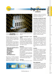
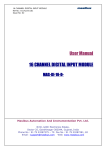
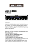
INSTRUCTION MANUAL
1.
“DIGICROWN PROBING LINE” SYSTEM INTRODUCTION.............. 4
2.
APPLICATION NOTES......................................................................... 6
3.
ELECTRICAL CONNECTIONS ............................................................ 7
4.
INPUT/OUTPUT CONFIGURATION .................................................... 8
4.1.
4.2.
4.3.
4.4.
OFF-LINE MODE ............................................................................... 8
ADDRESSING MODE .......................................................................... 9
ON-LINE MODE ............................................................................... 10
FLOW-CONTROL APPLICATION ........................................................ 12
5.
APPLICATION NOTES DIGI “PBB” PUSH BUTTONS .................... 13
6.
UNIT OPERATING STATUS LED ...................................................... 14
6.1.
6.2.
“ON ERROR” OR “AUTOMATIC” MODES...................................... 15
“AUTOMATIC” MODE .................................................................... 16
7.
GROUND CONNECTION ................................................................... 17
8.
TECHNICAL SPECIFICATIONS......................................................... 20
9.
INSTALLATION DRAWINGS ............................................................. 21
9.1.
DIMENSIONAL DRAWINGS DIGI PBB UNIT ......................................... 23
10.
DECLARATION OF CONFORMITY ............................................... 24
11.
ORDER CODES .............................................................................. 25
2
3
1. “DIGICROWN PROBING LINE” SYSTEM INTRODUCTION
DigiCrown is a flexible measuring system (from 1 to 372 sensors) configured in
networks (from 1 to 12), which can be connected to PCs using a RS232 serial/USB
interface or RS485 dedicated interface cards for PCI or ISA BUS.
The diagram below shows the elements of the DigiCrown system in the possible
configurations. This user manual provides in-depth information about operation of the
DigiCrown I/O and DigiCrown pbb units.
4
/USB
NET 1
NET 1
NET 2
MAX 6 CARDS
5
2. APPLICATION NOTES
The I/O module is used to manage digital
input/output signals. Typical applications for this
device are management of lamp indications,
solenoid valves (through power relays) or
acquisition of input signals by local cycle
START/STOP push-button panels, limit switches,
etc.
Each I/O module can manage any combination of
up to a maximum of 8 digital inputs/outputs (e.g.: 4
inputs + 4 outputs, 2 inputs + 6 outputs, etc.),
using a 15-pin D-sub connector.
The system limit is 32 I/O modules (total = 256
inputs/outputs).
This device is available in SINK, SOURCE and
SINK ONLY INPUT versions, to guarantee
maximum flexibility for use according to the
application to be managed.
Ext. +24Vdc
L=0.5m
PLC
SWITCH BOX
LAMP
RELAYS
L=2.5m
Digi PBB
(integrated switch box)
General
(switch box)
The I/O module is mounted on the DigiCrown bus unit, which is used for
communication with the data acquisition system with a standard RS-485 serial
connection. A 9-pin D-sub connector is used for the connection to the bus module
and also supplies electrical power to the control part and, in the case of the ONLY
INPUT module, to the interface part.
Each I/O module also incorporates a LED for a rapid diagnosis of the unit’s
operating status (see section 5).
6
3. ELECTRICAL CONNECTIONS
WHITE
PURPLE
YELLOW
GREEN
15-PIN MALE CONNECTOR
LIGHT BLUE
GREY
DARK BLUE
PINK
BROWN
BLACK
ORANGE
N.C. for “ONLY
INPUT” I/O module
RED
Pins 1 - 8 of the 15-pin male D-sub connector are used to connect the I/O module to
external signals.
Pins 9 - 10 and 14 - 15 are used to supply the 24V dc to the interface part. The
electrical power supply is divided over four pins to guarantee an optimum current
flow. To avoid overloads on the wires the 24V dc must be wired on all four pins.
Note: the power supply voltage on the 15-pin D-sub connector must be of the SELV
type and isolated from the bus voltage.
For the “ONLY INPUT” I/O module the electrical connections are the same, except
there is no 24V dc power supply. Therefore, pins 14 and 15 are not connected.
7
4. INPUT/OUTPUT CONFIGURATION
To configure the inputs/outputs on the DigiCrown I/O module you must install one of
the following pieces of software: QSPC, Easy Acquisition or Marposs Driver Library.
Below are the basic steps for I/O module set-up. For further information about the
MDHQSPC driver, consult manual D29499006I available on our web site:
www.testar.com.
4.1.
Off-Line Mode
1.
Create a new NET by selecting the type of interface with the management PC:
isa, pci card or 232/USB module.
2.
Select the I/O unit by clicking on the relative button
“Insert” to insert the I/O modules present in the NET.
3.
Finally, press “Save” to save the current NET, and “Apply” to activate the
configuration.
8
(
), and press
4.2.
Addressing mode
1.
Click on the “Addressing ON/OFF” button
2.
Press “OK” Æ
(
).
N.B.: the addressing procedure for the I/O modules is the same in both
“Automatic” and “Manual” modes.
3. Type in the serial number of the I/O module and press “Save”.
4. Alternatively, you can set the address for the module by physically
changing the status of an input; usually: press a cycle
START/STOP button, activate a limit switch contact, etc.
9
4.3.
On-line Mode
1.
Go to the on-line step by clicking on this button:
2.
Open the window below by clicking on the first I/O module to be configured:
3.
Press the “Db” button:
4.
Configure the I/O module’s digital inputs/outputs using the window shown
below. By default all bits are enabled as “Input/Output”.
BIT NOT USED
BIT ENABLED AS
BOTH INPUT
AND OUTPUT
ONLY INPUT
NEGATED INPUT
ONLY OUTPUT
NEGATED OUTPUT
10
5.
Press
to save the settings to the I/O module memory.
6.
Finally, close the window by pressing:
7.
Repeat steps 2 to 6 for all of the other I/O modules in the NET.
11
4.4.
Flow-Control Application
The digital input/output driver interfaces with the Marposs data processing software
(QSPC, Easy Acquisition…) using the Flow-Control application. This application
allows a specific function to be associated with each digital signal arriving from the
I/O module. To avoid conflicts with the DigiCrown I/O module configuration driver,
set each bit to “Input/Output” (see image below).
In this way assignment of the digital inputs/outputs of each bit will be managed
completely by the Flow-Control application (see example below). If there are two or
more modules in the NET, the bits are numbered sequentially: module 1 (bits 1 - 8),
module 2 (bits 9 - 16), module 3 (bits 17 - 24), etc.
For in-depth information about the Flow-Control Environment consult manual
D29407237I.
12
5. APPLICATION NOTES DIGI “PBB” PUSH BUTTON
The DigiCrown pbb push button
implements the I/O unit, allowing to
control eight digital inputs by means of
ON/OFF buttons and a four positions
selector.
Typically the buttons are used for
START/STOP sequences and data
acquisitions, while the selector for
setting a different working piece to be
measured.
Besides the 15-pin female D-sub port
used for connecting the I/O (ONLY INPUT) module, the push button
includes a 9-pin female connector for linking an external footswitch.
It follows the frontal view of the Digi pbb push button with the relevant
digital bit associated to each switch.
•
•
•
•
•
•
•
•
Button 1 = bit 0
Button 2 = bit 1
Button 3 = bit 2
Button 4 = bit 3
Selector position A = bit 7
Selector position B = bit 6
Selector position C = bit 5
Selector position D = bit 4 (*)
(*) The bit 4 reserved to the “D” position of the selector, it’s automatically
assigned to the footswitch by unscrewing the 9-pin male connector.
The following MARPOSS footswitches are compatible with the push button:
• Quick Read footswitch (code 6738099030)
• E4N footswitch (code 6738099015)
• E9066 footswitch (code 6131600810) – the adapter (code
4701300042) is required.
13
6. UNIT OPERATING STATUS LED
The type of light indication by the red LED on the I/O module indicates the unit
operating status. LED flashing modes are as follows:
•
“ON ERROR” (LED is only activated when an error is generated – sec. 5.1)
•
“AUTOMATIC" (mode which includes both ON ERROR indication and brief
flashes to indicate network sessions pending – sec. 5.2).
14
6.1.
“ON ERROR” or “AUTOMATIC” Modes
Notes:
(1) HW ERROR Æ general hardware and bootstrap errors
(2) APPLICATION ERROR Æ specific I/O errors
(3) COM ERROR Æ error in RS-485 serial communication
15
6.2.
“AUTOMATIC” Mode
Notes:
(4) OK Æ optimum network operation
(5) APPLICATION SESSION PENDING Æ specific I/O errors
(6) NETWORK SESSION PENDING Æ identification session for various network components
16
7. GROUND CONNECTION
In this chapter are reported different technical solutions in order to make sure the
DigiCrown system is properly grounded, according to the NET’s configuration and
to the lay-out of the different units.
The purpose of ground connection is to minimize as much as possible the
electrical noise and the interference, typically affecting the measurement
signal.
The ground connections schemes reported in this paragraph represent the optimal
solution in order to have a system fully compatible with the EMC standards,
according to the following directives:
-
73/23/EEC
2004/108/CE
EN55022: 1998 (EMC)
EN55024: 1998 (EMC)
If for a specific application the customer considers such technical solutions not
required, Marposs is not responsible for any possible inaccurate working condition
of the devices.
•
Bench application n. 1
The whole DigiCrown system (control + measurement) has been placed on a
single bench gauge.
PC
serial link
box
D
A
p.e.
The “D” equipotential connection between the box modules and the
transducers support frame, can be done whether a metallic conductive frame
is used. In the glass gauging applications the transducers support frame is
usually not a conductive material and the transducers are typically insulated, in
this case no ground connection is required.
17
•
Bench application n. 2
In case the control system (PC…) is placed on a bench while the transducers
and the box modules on another, we suggest to set-up an equipotential link as
shown in the points: A + D + E.
Power
supply
unit
PC
serial link
D
A
E
A.C.
Main
power
p.e.
•
Bench application n. 3
If the DigiCrown system is split on two or more benches, we suggest to set-up
an equipotential link as shown in the points: A + D + E + F + G.
Power
supply
unit
Power
supply
unit
Pc
serial link
box
serial link
G
F
A
E
D
p.e.
box
A.C.
Main
power
A.C.
Main
power
18
•
Automatic machine application
For such applications it is strongly suggested to provide the box units and the
transducers support frame with an equipotential link: in the automatic machine
applications the eddy-currents normally flow in the transducer’s shield.
Electrical cabinet
Pc
Measuring machine
box
serial link
pe
Ground bar
Ground bar
Equipotential
link
19
Metallic connection
between the modules
and the transducers
8. TECHNICAL SPECIFICATIONS
DigiCrown I/O (SINK version) / code 767I000000
Power supply (bus)…………...+7.5V dc (-10% + 30%)
Current absorption (bus)….....40mA
Power supply (V I/O)…..……...24V dc (± 20%)
Current absorption (I/O)………15mA (no output active)
I/O size……….………………...…8 input and/or output bits, optoisolated, individually selectable
Input specifications…………....Voff (min): V I/O - 5V; Von (max): V I/O - 15V
OUT capacity……….……...…...200mA (per OUT)
- outputs total max. current: 800mA (temp. = 0 to +50°C)
- outputs total max. current: 700mA (temp. = 0 to +60°C)
I/O protection…………………….power supply inversion, output overload
Dimensions………………………see section 5
DigiCrown I/O (SOURCE version) / code 767I010000
Power supply (bus)…………...+7.5V dc (-10% + 30%)
Current absorption (bus)….....40mA
Power supply (V I/O)…..……..…24V dc (± 20%)
Current absorption (I/O)………25mA (no output active)
I/O size……….………………...…8 input and/or output bits, optoisolated, individually selectable
Input specifications……………Voff (max): 5V; Von (min): 15V
OUT capacity……….……...…...200mA (per OUT)
- outputs total max. current: 800mA (temp. = 0 to +50°C)
- outputs total max. current: 700mA (temp. = 0 to +60°C)
I/O protection…………………….power supply inversion, output overload
Dimensions………………………see section 5
DigiCrown I/O (ONLY INPUT version) / code 767I020000
Power supply (bus)………………+7.5V dc (-10% + 30%)
Current absorption (bus)….........50mA (all inputs activated)
I/O size……….…………………….8 input bits (not isolated)
Input specifications………………OFF: Rswitch > 500 KΩ
ON: Rswitch < 3300 Ω
Dimensions………………………see section 5
CAUTION!!
Use a SELV power source
(as defined by EN60950)
20
9. INSTALLATION DRAWINGS
I/O module
Fastening
tongue
Bus module
Locking device
21
Hooking of I/O module to bus connector
Dimensions of fastening to stand
22
9.1.
Dimensional drawings Digi PBB unit
23
10. DECLARATION OF CONFORMITY
MARPOSS S.p.A. hereby declares that the devices referred to in this
manual conform to
safety requirements and EMC electromagnetic
compatibility requirements, in accordance with the following directives:
73/23/EEC
2004/108/EC
of 19-02-1973 (LOW VOLTAGE directive)
of 20-01-2005 (EMC directive)
The apparatuses were designed, assembled and tested in conformity with
the following European standards:
EN60950:
2000
EN61326 - 1: 1997
EN61326/A1: 1998
(Safety)
(EMC)
(EMC)
24
11. ORDER CODES
The tables below provide a summary of the order codes for all components in the
DigiCrown Probing Line.
The parts highlighted relate to elements referred to in this manual.
INTERFACES
ORDER CODE
ACCESSORIES
DESCRIPTION
ORDER CODE
DIGI CROWN BOX
767X000200
DIGI CROWN BOX + RAM
6872030010
DIGI CROWN BUS
767Y000000
DIGI CROWN 232
6872030011
DIGI CROWN PSC
767Y010000
DIGI CROWN USB
4147000013
EU PLUG
767W000000
DIGI CROWN PSU (110-240Vac / 7,5Vdc)
4147000014
USA PLUG
UK PLUG
767W010000
6355200000
DESCRIPTION
767X000000
END LINE CONNECTOR
DIGI CROWN PSU (24Vdc / 7,5Vdc)
4147000015
767I000000
DIGI CROWN I/O SINK
4147000016
EU CABLE
767I010000
DIGI CROWN I/O SOURCE
4147000017
USA CABLE
767I020000
DIGI CROWN I/O ONLY INPUT
6139013200
DIGI CROWN PBB
6355321000
DIGI CROWN PCI
6355322000
DIGI CROWN ISA
EXTENSIONS
ORDER CODE
SW packages
DESCRIPTION
6738057016
CONNECTION CABLE 2m
6738057023
6738057022
6738057017
CONNECTION CABLE 25m
ORDER CODE
DESCRIPTION
CM2Z22MA00
QSPC
CONNECTION CABLE 10m
CM2F22MA02
EASY ACQUISITION
CONNECTION CABLE 15m
CM2A12MA01
MARPOSS DRIVER LIBRARY
25
Notes
___________________________________________
___________________________________________
___________________________________________
___________________________________________
___________________________________________
___________________________________________
___________________________________________
___________________________________________
___________________________________________
___________________________________________
___________________________________________
___________________________________________
___________________________________________
___________________________________________
___________________________________________
___________________________________________
___________________________________________
___________________________________________
___________________________________________
___________________________________________
___________________________________________
___________________________________________
26
Notes
___________________________________________
___________________________________________
___________________________________________
___________________________________________
___________________________________________
___________________________________________
___________________________________________
___________________________________________
___________________________________________
___________________________________________
___________________________________________
___________________________________________
___________________________________________
___________________________________________
___________________________________________
___________________________________________
___________________________________________
___________________________________________
___________________________________________
___________________________________________
___________________________________________
___________________________________________
27
2002/95/EC
2002/96/EC
This product and any part which can be mechanically separated from it must not be dispersed to the
environment or disposed of as municipal or generic waste (Law for national adoption of European directives
2002/95/EC and 2002/96/EC and others). The provisions of the law only apply to products identified as WEEE
with the appropriate logo and on sale since 13 August 2005. WEEE products, once decommissioned, may
contain substances and parts which are harmful to people and the environment and which must undergo
professional treatment to allow their re-use, recycling and definitive disposal. Deliver WEEE products to an
authorised WEEE treatment centre, or contact the local body in charge of such services or the nearest Marposs
support centre for information. Illegal disposal of WEEE products is an offence which will be punished by law.
A full, up-to-date list of addresses is available at the official Marposs web site: www.marposs.com - www.testar.com
D4340037IF – Edition 12/2007 – Details may change without prior notice.
© Copyright 2007 MARPOSS S.p.A. (Italy) – All rights reserved.
MARPOSS, and other names/signs relative to Marposs products, referred to or shown in this document are registered trade marks
or trade marks of Marposs in the United States and in other countries. Any third party rights relating to trade marks or registered
trade marks referred to in this document are recognised for the respective holders.
Marposs has an integrated Company Management system for quality, the environment and safety, with the following
certification: ISO 9001, ISO 14001, OHSAS 18001 and QS9000 T&E. Marposs has also been awarded EAQF 94 and the
Q1-Award.
28