1
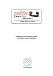
INSTRUCTION MANUAL
1. INTRODUCTION TO DIGICROWN PROBING LINE SYSTEM ........................... 4
2. NETWORK POWER SUPPLY UNIT .................................................................... 6
2.1. CASES IN WHICH A PSU MODULE IS REQUIRED ..................................................... 7
3. END LINE CONNECTOR ..................................................................................... 8
4. CONFIGURATION OF POWER SUPPLY UNIT (100-240VAC).......................... 9
5. CONFIGURATION OF POWER SUPPLY UNIT (24 VDC) ................................ 10
6. ELECTRICAL PROTECTION OF POWER SUPPLY UNIT ............................... 11
7. GROUND CONNECTION ................................................................................... 12
8. TECHNICAL SPECIFICATIONS ........................................................................ 15
9. INSTALLATION DIAGRAMS ............................................................................. 16
10. DECLARATION OF CONFORMITY ............................................................... 18
11. SUMMARY TABLES OF ORDERING CODES............................................... 19
-2-
-3-
1. INTRODUCTION TO DIGICROWN PROBING LINE SYSTEM
The DigiCrown is a flexible measuring system (from 1 to 372 sensors), configured in
networks (from 1 to 12) that can be connected to a PC via an RS232/USB serial
interface or dedicated RS485 interface cards for PCI or ISA bus.
The diagram below shows the elements of the DigiCrown system in their possible
configurations. This user manual follows up the installation of the DigiCrown psu unit.
-4-
/USB
NET 1
NET 1
NET 2
MAX 6 CARDS
-5-
2. NETWORK POWER SUPPLY UNIT
The DigiCrown psu unit (henceforth called psu) is formed of a stabilized power
supply unit and an interface module to be connected to the network in the first
module position. The psu unit supplies the required electric power, as reported on
the Technical Specification (chapter 6).
The connection of the psu module to the network is made via the DigiCrown psc
connector, whose structure is identical to that of the bus connector for DigiCrown
box modules. The only variation is the polarity inversion of the Cannon 9-way sub
D-type connector (Fig. 1) and the power supply interruption on the bus.
Polarity
inversion
Fig. 1
2.1. Cases in which a psu module is required
This power supply unit is always required in the following cases:
a)
the network management is achieved with an RS-232 serial standard by means
of a DigiCrown 232/USB module (Fig. 2);
Fig. 2
b)
the power supply generated by the DigiCrown PCI/ISA modules (RS-485) is
insufficient for a long cable: a psu module is installed in order to cope with the
voltage drops (see example reported on Fig. 3).
When the network is connected to the computer via a pci/isa card, it is usually not
necessary to install an additional power supply unit, unless there is the situation
described in point B.
Fig. 3
-7-
3. END LINE CONNECTOR
The end line connector (Fig. 4) is
inserted as a closing element in
each NET, and physically
applied to the last DigiCrown
bus module.
The function of this device is to
indicate, by means of its
integrated LED, whether the
network is supplied with power
at a voltage sufficient to ensure
the correct operation of all the
modules that are present.
Fig. 4
There are three types of display in the network end connector:
•
LED OFF Æ voltage in bus insufficient
•
LED ON (green light) Æ voltage OK
•
LED FLASHING (red/green light) Æ communication in bus active
Should the voltage be insufficient to supply the network (point 1), it is necessary to
install an auxiliary psu unit. Another solution may be for the user to remove some
modules in sequence until the LED of the network end connector lights up, and to
create an additional network (managed by means of a 232 interface or pci/isa card).
-8-
4. CONFIGURATION OF POWER SUPPLY UNIT (100-240VAC)
The ordering code 767W000000 identifies the network power supply unit that
functions with a 100-240 VAC input voltage. This code includes several elements,
but is not ready for use: it is necessary to order, as an accessory, the psc module
(code 6872030011), and also the element for the connection to the local network
(network cables and plugs complying with the standard adopted in the country
where the equipment is used).
Below, the available configurations. with the relevant ordering codes, are shown.
EU extension
USA extension
EU plug
USA plug
UK plug
-9-
5. CONFIGURATION OF POWER SUPPLY UNIT (24 VDC)
The ordering code 767W010000 identifies the network power supply unit that
functions with a 24 VDC input voltage (machine voltage). The 24 VDC psu module
is supplied with a 5m long electrical connection cable.
To complete the configuration of the 767W010000, it is necessary to order the psc
module (code 6872030011).
- 10 -
6. ELECTRICAL PROTECTION OF POWER SUPPLY UNIT
The power supply unit (Fig. 5) connected to the 100-240Vac psu module is
equipped with the following protection systems:
•
Protection against overload and short circuit: the circuit is equipped, in series,
with a renewable fuse that is blown if there is an excessive current absorption.
As soon as these abnormal conditions disappear, an automatic system with which
the psu module is equipped restores operating conditions without the need for any
manual action.
Fig. 5
)
)
The power supply must be installed in dry environments. The unit
is specifically designed for indoor use only.
- 11 -
7. GROUND CONNECTION
In this chapter are reported different technical solutions in order to make sure the
DigiCrown system is properly grounded, according to the NET’s configuration and to
the lay-out of the different units.
The purpose of ground connection is to minimize as much as possible the
electrical noise and the interference, typically affecting the measurement
signal.
The ground connections schemes reported in this paragraph represent the optimal
solution in order to have a system fully compatible with the EMC standards,
according to the following directives:
-
73/23/EEC
2004/108/CE
EN55022: 1998 (EMC)
EN55024: 1998 (EMC)
If for a specific application the customer considers such technical solutions not
required, Marposs is not responsible for any possible inaccurate working condition
of the devices.
•
Bench application n. 1
The whole DigiCrown system (control + measurement) has been placed on a
single bench gauge.
PC
serial link
box
D
A
p.e.
The “D” equipotential connection between the box modules and the
transducers support frame, can be done whether a metallic conductive frame
is used. In the glass gauging applications the transducers support frame is
usually not a conductive material and the transducers are typically insulated, in
this case no ground connection is required.
- 12 -
•
Bench application n. 2
In case the control system (PC…) is placed on a bench while the transducers
and the box modules on another, we suggest to set-up an equipotential link as
shown in the points: A + D + E.
Power
supply
unit
PC
serial link
D
A
E
A.C.
Main
power
p.e.
•
Bench application n. 3
If the DigiCrown system is split on two or more benches, we suggest to set-up
an equipotential link as shown in the points: A + D + E + F + G.
Power
supply
unit
Power
supply
unit
Pc
serial link
box
serial link
G
F
A
E
D
p.e.
box
A.C.
Main
power
A.C.
Main
power
- 13 -
•
Automatic machine application
For such applications it is strongly suggested to provide the box units and the
transducers support frame with an equipotential link: in the automatic machine
applications the eddy-currents normally flow in the transducer’s shield.
Electrical cabinet
Pc
Measuring machine
box
serial link
pe
Ground bar
Ground bar
Equipotential
link
- 14 -
Metallic connection
between the modules
and the transducers
8. TECHNICAL SPECIFICATIONS
DigiCrown psu (100-240 VAC) / code 767W000000
Power supply …………………...100-240Vac / 47-63Hz / 400mA
Output……………………………..7,5Vdc / 1,7A
Operating temperature…..……..0 to 40°C
Storing temperature...........…....-20 to +70°C
Protection degree....…………..…IP 43 (on side of interface with bus)
Protection against overload……with automatic resetting
Dimensions……………………..…see Chapter 8
DigiCrown psu (24 Vdc) / code 767W010000
Power supply ……….……………..24Vdc (-20% / + 20%)
Output…………………….……..…..7,5Vdc / 1,8A
Current absorption………….…….1A
Operating temperature…..….……0 to 40°C
Storing temperature……………..-20 to +70°C
Protection degree..……….………IP 43 (on side of interface with bus)
Protection against overload...…with automatic resetting
Protection against inversion…...with automatic resetting
Dimensions………..………………see Chapter 8
- 15 -
9. INSTALLATION DIAGRAMS
DigiCrown psu module
Fastening
tongue
- 16 -
DigiCrown psc module
Locking device
Dimensions of fastening to stand
- 17 -
10. DECLARATION OF CONFORMITY
MARPOSS S.p.A. hereby declares that the devices described in this manual comply
to the
safety requirements and EMC electromagnetic compatibility requirements,
in compliance with the following directives:
73/23/EEC
of 02-19-1973
(LOW VOLTAGE directive)
2004/108/CE
of 01-20-2005
(EMC directive)
The devices have been designed, assembled and tested in compliance with the
following European standards:
EN60950
: 2000
(Safety)
EN61326 - 1 : 1997
(EMC)
EN61326/A1 : 1998
(EMC)
- 18 -
11. SUMMARY TABLES OF ORDERING CODES
The tables below are a general summary of the ordering codes for all the
components of the DigiCrown Probing Line.
The highlighted parts are the elements described in this manual.
INTERFACES
ORDER CODE
ACCESSORIES
DESCRIPTION
767X000000
DIGI CROWN BOX
767X000200
767Y000000
ORDER CODE
DESCRIPTION
6355200000
END LINE CONNECTOR
DIGI CROWN BOX + RAM
6872030010
DIGI CROWN BUS
DIGI CROWN 232
6872030011
DIGI CROWN PSC
767Y010000
DIGI CROWN USB
4147000013
EU PLUG
767W000000
DIGI CROWN PSU (110-240Vac / 7,5Vdc)
4147000014
USA PLUG
767W010000
DIGI CROWN PSU (24Vdc / 7,5Vdc)
4147000015
UK PLUG
767I000000
DIGI CROWN I/O SINK
4147000016
EU CABLE
767I010000
DIGI CROWN I/O SOURCE
4147000017
USA CABLE
767I020000
DIGI CROWN I/O ONLY INPUT
6355321000
DIGI CROWN PCI
6355322000
DIGI CROWN ISA
EXTENSIONS
ORDER CODE
SW packages
DESCRIPTION
6738057016
CONNECTION CABLE 2m
6738057023
6738057022
6738057017
CONNECTION CABLE 25m
ORDER CODE
DESCRIPTION
CM2Z22MA00
QSPC
CONNECTION CABLE 10m
CM2F22MA02
EASY ACQUISITION
CONNECTION CABLE 15m
CM2A12MA01
MARPOSS DRIVER LIBRARY
- 19 -
2002/95/CE
2002/96/CE
The product and any part that can be mechanically separated from it must not be disposed of the environment
and must not be disposed of as municipal or general waste (Law for national adoption of European directives
2002/95/EC and 2002/96/EC and others). The provisions of the law only apply to products identified as WEEE
(waste electrical and electronic equipment) marked with the appropriate symbol and in any case put on the
market after 13 August 2005. Once put out of use, the WEEE product may contain substances and parts that
are harmful to human health and the environment and which must be subject to professional treatment for
reuse, recycling or definitive disposal. Deliver the WEEE product to an authorised WEEE treatment centre, or
contact the local organisation responsible or your nearest Marposs service centre for information. Illegal
disposal of a WEEE product is a crime punishable by penalties.
For a full list of address locations, please consult the Marposs official website: www.marposs.com - www.testar.com
D4340036GF - Edition 02/2006 - Specifications are subject to modifications
© Copyright 2006 MARPOSS S.p.A. (Italy) - All rights reserved.
MARPOSS, and Marposs product names/signs mentioned or shown herein are registered trademarks or trademarks of Marposs in
the United States and other countries. The rights, if any, of third parties on trademarks or registered trademarks mentioned in the
present publication are acknowledged to the respective owners.
Marposs has an integrated system to manage the Company quality, the environment and safety, attested by ISO 9001,
ISO 14001, OHSAS 18001 and QS9000 T&E certifications. Marposs has further been qualified EAQF 94 and has
obtained the Q1-Award.
- 20 -