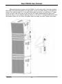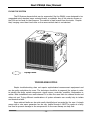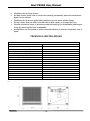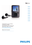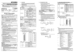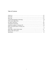
1
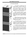
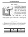
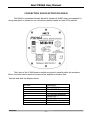
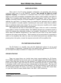
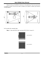
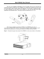
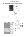
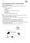
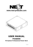
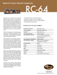
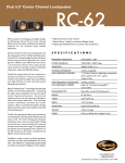
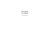
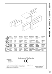
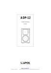
USER MANUAL PXH64 PX System Mid/High Element V102013 Next PXH64 User Manual www.next-proaudio.com CONTENT INTRODUCTION -2- SAFETY FIRST -2- UNPACKING -3- PX SYSTEM OVERVIEW -4- PXH64 OVERVIEW -5- CABLE SELECTING -5- CONNECTION AND ELECTRIC DIAGRAM -6- AMPLIFICATION -8- PX SYSTEM DEPLOYMENT -8- TROUBLESHOOTING - 14 - TECHNICAL SPECIFICATIONS - 15 - WARRANTY - 16 - SPARE PARTS - 16 - ACCESSORIES - 16 - CONTACTS - 17 - V102013 -1- Next PXH64 User Manual www.next-proaudio.com INTRODUCTION Thank you for purchasing a NEXT PXH64. This manual will provide you with important information about your NEXT PXH64. Please devote some time reading this manual, and keep it close for future reference. NEXT-proaudio is concerned with your safety and wellbeing, so please follow all instructions and heed all warnings. Also, a better understanding of some specific features of the PXH64 will help you to operate your system to its full potential. SAFETY FIRST It’s important that loudspeaker systems are used in a safe manner. Please take some time to review the following points concerning safe use of the NEXT PXH64 element. DANGER – HEARING DAMAGE NEXT PXH64 is capable of producing extremely high sound pressure levels and should be used with care. Hearing loss is cumulative and can result from levels above 90dB if people are exposed for a long period. Never stand close to loudspeakers driven at high levels. -2- Next PXH64 User Manual www.next-proaudio.com Stacking Always ensure that the floor or structure where the stack will take place is even and can withstand the weight of the complete stack. Do not stack speakers too high, especially outdoors where winds could topple the stack. Be aware that speakers working at very high power levels generate vibrations that can creep the systems. Take additional measures to prevent this if needed. Place cables in a way that they do not present a trip hazard. Don’t place any objects on top of the stack, they can fall accidentally and cause injuries. Do not attempt to move the enclosures while connected. Try not to operate the PXL118 under heavy rain or moisture, it is weather-resistant but not completely “weather-proof”. Also do not expose the systems to extreme heat or cold conditions to prevent component damage. _______________________________________________________________ Rigging and suspension WARNING: DO NOT SUSPEND PXL118 Sub1. In the NEXT PX system only the PXL118 Sub 2, PXH64 and PXA8000 are designed to be suspended, PXL118 Sub 1 was not designed having suspended use in mind. Before rigging or suspending any NEXT PX system component, inspect all components and all hardware for any signs of damage or missing parts. If you find any damaged, corroded or deformed parts, do not use them, replace them immediately. Do not use hardware that isn’t load rated or that its rating is not enough to handle the system’s weight with a good safety factor. Don’t forget that the hardware won’t just hold the systems weight. It has to be sturdy enough to handle dynamic forces like winds without any part deformation. NEXT PX system installation should only be carried out by qualified personnel. Always use adequate protective clothing and equipment to prevent possible injuries. Isolate the surrounding area during installation and operation, to prevent general public presence near the systems. Also, be sure you understand all local and national regulations regarding equipment installation. Failure to comply with these instructions may result on injury or death. UNPACKING Each NEXT PX system component is built in Europe (Portugal) by NEXT-Proaudio, to the highest standard and thoroughly inspected before it leaves the factory. When unpacking the NEXT PXH64, examine it carefully for any signs of possible transit damage and inform your dealer immediately if any such damage is found. It is suggested that you retain the original packaging so that the system can be repacked in the future if necessary. Please note that NEXT-proaudio and its authorized distributors cannot accept any responsibility for damage to any returned product through the use of non-approved packaging. V102013 -3- Next PXH64 User Manual www.next-proaudio.com PX SYSTEM OVERVIEW The PX system is a complete plug ‘n’ play, processor-controlled, horn-loaded stacking P.A. system optimized for flexible, very high power, modular array configurations, for use in festival tents, clubs and at open-air events. Very high sound pressure, extreme reliability, easy transportation, fast setting-up times and easy cabling, are just some of the important practical advantages of PX system complete systems. Setting the highest standards in audio performance, reliability and price, for situations where line arrays do not present themselves as the best solution in terms of cost, complexity and flexibility, the PX system is a perfect alternative, offering easier set up, less cabling, and simpler operation. High-quality components combined with the new Mid/High, coaxially mounted horns, the hybrid bass horns and the latest processor DSP technology, deliver maximum sound pressure and superlative audio performance. The components of the PX System can be quickly and easily configured to cover an enormous range of different sound reinforcement applications in venues of all shapes and sizes without any need for complex calculations, controller adjustments and limiter settings. If extreme sub levels are needed for an open air DJ event, just add another sub on each side. If the brass band in the beer tent wants ultra-wide coverage, just use two subs and two angled tops per side. If a Top 40 band suddenly finds itself playing to an audience of 3000, the same system amp can drive four subs and two tops per side. -4- Next PXH64 User Manual www.next-proaudio.com PXH64 OVERVIEW The NEXT PXH64 Mid/High element is part of the PX system. The NEXT PXH64 was engineered to be a powerful medium to longthrow, mid/high frequency cabinet in a coaxial configuration, covering the frequency range from 150Hz up to 19kHz.To obtain the highest possible on-axis sound pressure levels and clear and intelligible sound reproduction over long distances, the PXH64 mid/high unit is entirely horn-loaded. The coaxial arrangement of the High Frequency CD horn and the Mid Frequency 12″ speaker (also horn-loaded) creates a precise coverage pattern of 60°H x 40°V over a frequency range from 400Hz - 17kHz, ensuring equal sound within the coverage area. The HF range from 1.150kHz upwards is reproduced by a Neodymium 1.4” driver with a 3” voice coil and a Constant Q horn, whilst coverage in the mid-range from 150Hz to 1.25kHz is provided by a low power compression 12” driver loaded into a midrange horn. Wider coverage can be achieved using multiple elements, laterally stacked or flown. CABLE SELECTING Selecting a cable consists of calculating the correct cable section (size) in relation to the load impedance and the required cable length. A small cable section will increase its serial resistance, which will induce power-loss and response variations (damping factor). The following table indicates, for 3 common sizes, a cable length with a maximum serial resistance equal to 4% of the load impedance (damping factor = 25): Cable section 1.5 mm² 2.5 mm² 4 mm² V102013 Maximum Length related to load impedance 8Ω 4Ω 12 m [40 ft] 6 m [20 ft] 20 m [64 ft] 10 m [32 ft] 32 m [104 ft] 16 m [52 ft] -5- Next PXH64 User Manual www.next-proaudio.com CONNECTION AND ELECTRIC DIAGRAM The PXH64 is connected through Neutrik® Speakon® NL8FC plugs (not supplied). A wiring description is printed on the connections panels located on back of the cabinet. The 8 pins of the 2 NL8 Speakon sockets are wired in parallel within the enclosure. Either connector can be used to connect to the amplifier or another Sub. See the table and the diagram below: NL8 PIN 1+ 12+ 23+ 34+ 4- Description PXL118 SUB1 Reserved PXL118 SUB1 Reserved PXL118 SUB2 Reserved PXL118 SUB2 Reserved PXH64 MID + PXH64 MID PXH64 HIGH + PXH64 HIGH - -6- Next PXH64 User Manual www.next-proaudio.com Electric Diagram MF HF MF+ (Grey); HF+ (Red) MF - (Black); HF - (White) V102013 -7- Next PXH64 User Manual www.next-proaudio.com AMPLIFICATION When used in the PX system standard configuration, all processing and powering needs are taken care of by the PXA80001 element. Care should be taken to avoid amplifier clipping. It is important to understand that a low power amplifier driven into clipping is more likely to damage a loudspeaker than a higher power amplifier used within its ratings. This is because music signals have a high peak-to-average "crest" factor. When an amplifier is severely overdriven, its output waveform is “clipped” (its peaks are squared off) – reducing the crest factor. In extreme cases, the waveform can approach that of a square wave. An amplifier is normally capable of producing far more power under these conditions than its undistorted rated power output. The use of very high power amplifiers with outputs much greater than those recommended is discouraged. Care should also be taken to avoid switch-on surges, which can result in momentary power peaks in excess of specified ratings. The PXA8000 element has a protection circuit to avoid this between the integrated processor and amplifier. Nevertheless, this circuit only works within the PXA8000 components, if you switch off your mixer or any other exterior component the power surge will occur. When powering up a sound system it is important to switch on the amplifiers last, after the mixer and control electronics have stabilised. When powering down the system, reverse the sequence and switch off the amplifiers first. PX SYSTEM DEPLOYMENT The PX System is a versatile, easy and fast deployment system. It can be used ground-stacked or suspended. Combined with the optional splay adjustment kit NC07712, you can adjust the splay as needed in 5º steps up to 10º front or rear. GROUND STACKING There are some things you should know about ground-stacking the PX System. PXL118 SUB1 and SUB2 have a correct order on the stack. Always start with SUB1 from the ground. Other than that, the stack is pretty standard. The PXH64 has two working positions. It can work in a H60º x V40º when there is only one vertical stack per side, or you can rotate it to achieve a H40º x V60º when you have a double stack on the same place. This way you’ll reduce the comb effects between those elements. You can also arrange it so you have up to 80º horizontal coverage. Of course, if you need more coverage, you can either triple stack, or if you don’t have the means, double stack in the H60º x V40º positioning. 1 Refer to PXA8000 manual for more information. -8- Next PXH64 User Manual www.next-proaudio.com Follow the lines on the PXH64 to help you on the positioning. Those lines aren’t just an aesthetic element. They tell you how to position your system to achieve your desired coverage pattern. Let’s proceed with a standard stack. Step 1. - Start with PXL118 Sub 1 and place PXL118 Sub 2 on top of it. PXL118 SUB 2 PXL118 SUB 1 V102013 -9- Next PXH64 User Manual www.next-proaudio.com Step 2. – Place the PXA8000 on top of the PXL118 SUB 2. Step 3. – Last, place the PXH64 on top of the PXA8000. It’s as easy as it can be. - 10 - Next PXH64 User Manual www.next-proaudio.com Ok, this is the standard configuration of the PX System. Now you can proceed and connect the system as explained on the PXA8000 user manual. But sometimes you may need to tilt the PXH64 a little to better address the audience. The PX System is towering by itself, it’s easily predictable you will need to tilt the PXH64. For that you will need the PX Splay adjustment kit mentioned earlier. This splay kit allows frontward tilt in 5º or 10º. NC07712 This kit can be applied connecting the PXH64 to the PXA8000 power-rack, or connecting the PXH64 to PXL118 Sub 2. The assembly method is exactly the same, so we’ll review only the assembly for a frontward tilt between the PXH64 and the PXA8000. Step 1. – Remove the upper two screws of the PXA8000 on the rear as shown in the picture: V102013 - 11 - Next PXH64 User Manual www.next-proaudio.com Step 2. – Remove the screw on the PXH64 rear group as shown in the image. Step 3. – Follow the full standard assembly as described earlier. Then, place the adjustment guides on the PXA8000 one at each side, like in the image below. Position the screws but do not tighten them just yet. - 12 - Next PXH64 User Manual www.next-proaudio.com After positioning the screws, pull the PXH64. You will notice that, if you don’t tighten the screws, the guide will position in a way that if you let it go down slowly, it will enter the cavity of the nearest angle. So, if you pull halfway and then let go, you will have a 5º splay, and if you pull it over to the top, it will enter the 10º cavity. Notice that this system only works the way up. If you want to descend from 5º or 10º into 0º, someone will have to hold the guides in place for you. When the guides reach the splay you want, tighten the screws. V102013 - 13 - Next PXH64 User Manual www.next-proaudio.com FLYING THE SYSTEM The PX System elements that can be suspended, like the PXH64, were designed to be suspended using standard cargo restraint tracks, or eyebolts. Any of the exterior screws on the PXH can be used for that purpose. The cabinet is steel braced from the inside. Despite that, hanging more than three units on the same vertical stack is not advised. - Flying Points TROUBLESHOOTING Simple troubleshooting does not require sophisticated measurement equipment and can be easily undertaken by users. The technique should be to segment the system in order to identify the faulty system component: signal source, controller, amplifier, loudspeaker or cables. Most installations are multi-channel. It is often the case that one channel works and others do not. Trying different combinations of system elements can usually help to isolate and locate the fault. Some cabinet faults can be quite easily identified and corrected by the user. A simple sweep with a sine wave generator can be very helpful though it MUST be made at a fairly low level to prevent damage to the components. A sine wave sweep can help find: - 14 - Next PXH64 User Manual www.next-proaudio.com Vibrations due to loose screws. Air-leak noises: check that no screws are missing, particularly where the accessories attach to the cabinet. Vibrations due to a front grille badly positioned on the quick release fixings. Foreign object that has fallen into the cabinet after repair or through the ports. Internal connection wires or absorbing material touching the loudspeaker diaphragm: check by removing the bass loudspeaker. Loudspeaker not connected or phase reversed following a previous inspection, test or repair. TECHNICAL SPECIFICATIONS PXH64 TECHNICAL SPECIFICATIONS Design Coaxial Horn Nominal Impedance (Mid/High) 8Ω/8Ω Continuous Power Handling (Mid/High) 800W/160W Sensitivity (1W/1m Half-Space) (Mid/High) 107dB/113dB Maximum SPL (calculated) (Mid/High) 136dB/135dB Frequency Response (-10dB) 130Hz - 18000Hz Dispersion H 60º x V 40º / H 40º x V 60º Crossover Frequency (active) 150Hz/1150Hz Components 1 x 12” Mid; 1 x 1.4” High Connectors 2 x Parallel Neutrik® NL8 Enclosure Material 15mm Birch Plywood Finish Black Textured Water-based paint Grille Metal grille with black acoustically-invisible foam Castors 4 (Optional) Rigging Tracks 16 (Optional) Dimensions (W x H x D) 616 x 612 x 641 mm Weight 46 Kg Dimensions V102013 - 15 - Next PXH64 User Manual www.next-proaudio.com WARRANTY NEXT products are warranted, by NEXT-Proaudio, against manufacturing defects in materials or craftsmanship over a period of 2 years from the date of original purchase. During the warranty period Next-proaudio will, at its discretion, either repair or replace products which prove to be defective provided that the product is returned in its original packaging, shipping prepaid, to an authorized NEXT-Proaudio service agent or distributor. NEXT-Proaudio cannot be held responsible for defects caused by unauthorized modifications, improper use, negligence, exposure to inclement weather conditions, act of God or accident, or any use of this product that is not in accordance with the instructions provided by NEXTProaudio. NEXT-Proaudio is not liable for consequential damages. This warranty is exclusive and no other warranty is expressed or implied. This warranty does not affect your statutory rights. SPARE PARTS Reference NC01710 NC03710 BB01261 BB05063 NCS05710 Description NEXT PXH64 Grille NEXT PXH64 60 x 40 1.4” Horn NEXT PXH64 HF 1.4” Driver NEXT PXH64 MF 12” Driver Next PXH64 Connections Back Panel ACCESSORIES Reference BA00004 VP11224 NC07712 Description Wheel Kit Cargo Restraint Track with Double Stud Ring NEXT M8 Eyebolt NEXT PX System Splay adjustment kit - 16 - Next PXH64 User Manual www.next-proaudio.com CONTACTS In case of any doubts or any information just: Write us: NEXT-PROAUDIO Rua da Venda Nova, 295 4435-469 Rio-Tinto Portugal Contact us: Tel. +351 22 489 00 75 Fax. +351 22 480 50 97 Send an e-mail: [email protected] Search our website: www.next-proaudio.com V102013 - 17 -