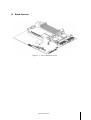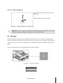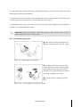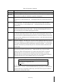
1
Server Board
User Manual
Nov. 2004 (Revision B, 5)
Copyright Notice
© 2004 Inventec Enterprise System Corporation (IESC). All rights reserved.
All product names or brands mentioned herein are the trademarks of IESC or their respective owners.
Contents
About this Manual..........................................................................................................................................i
Conventions..................................................................................................................................................i
Package Contents .........................................................................................................................................i
Safety Precautions ........................................................................................................................................i
Operation Safety.......................................................................................................................................i
Electrical Safety ......................................................................................................................................ii
Tools Required........................................................................................................................................iii
Regulatory and Integration Information.....................................................................................................iv
Regulatory Compliance Identification Numbers .................................................................................... iv
Product Regulatory Compliance ............................................................................................................ iv
Battery Replacement Notice ................................................................................................................... vi
1
Product Introduction .........................................................................................................................1-1
1.1
1.2
2
Product Features...........................................................................................................................1-1
Board Overview ...........................................................................................................................1-2
Hardware Operation..........................................................................................................................2-1
2.1
Power Off .....................................................................................................................................2-1
2.2
Back Panel Connectors.................................................................................................................2-2
2.3
Motherboard .................................................................................................................................2-3
2.3.1
Connector and Component Locations ..................................................................................2-3
2.4
Battery ..........................................................................................................................................2-1
2.4.1
To install the battery.............................................................................................................2-1
2.4.2
To remove the battery ...........................................................................................................2-2
2.5
Processor ......................................................................................................................................2-2
2.5.1
To install the processor.........................................................................................................2-3
2.5.2
To install the heat sink..........................................................................................................2-4
2.5.3
To remove the processor and heat sink.................................................................................2-4
2.6
System Memory ...........................................................................................................................2-5
2.6.1
To install a DIMM ................................................................................................................2-6
2.6.2
To remove a DIMM...............................................................................................................2-6
2.7
System Configuration Switch.......................................................................................................2-7
2.8
Optional SCSI Daughter Card ......................................................................................................2-7
2.8.1
To install the SCSI daughter card.........................................................................................2-8
2.8.2
To remove the SCSI daughter card .......................................................................................2-8
2.9
Optional Riser Card......................................................................................................................2-9
2.9.1
PCI-X Riser card ..................................................................................................................2-9
2.9.2
PCI-E Riser card ................................................................................................................2-10
3
Connector and System Configuration Switch..................................................................................3-1
3.1
Power Connectors ........................................................................................................................3-1
3.1.1
Main Power Connector (J11) ...............................................................................................3-1
3.1.2
Processor Power Connector (J10) .......................................................................................3-2
3.2
Front Panel Connector (J17).........................................................................................................3-2
3.3
IDE Connector (J9) ......................................................................................................................3-3
3.4
Floppy Connector (J12)................................................................................................................3-4
3.5
VGA Port (J40).............................................................................................................................3-4
3.6
Serial Port (J39)............................................................................................................................3-4
3.7
Keyboard and Mouse Ports (J41) .................................................................................................3-5
3.8
Back Panel USB Connector (J38) ................................................................................................3-6
3.9
Front Panel USB Connector (J8)..................................................................................................3-6
3.10 RJ45 Connectors (NIC) (J37).......................................................................................................3-7
3.11 Miscellaneous Connectors............................................................................................................3-7
3.11.1
Fan Connectors (J1, J2, J3, J4, J5, J6) ................................................................................3-7
3.12 System Configuration Switch Setting ..........................................................................................3-8
4
BIOS Setup .........................................................................................................................................4-1
4.1
Using the BIOS Setup Utility.......................................................................................................4-1
4.1.1
If You Cannot Access Setup ..................................................................................................4-1
4.1.2
Starting Setup .......................................................................................................................4-1
4.1.3
Setup Menus .........................................................................................................................4-1
4.2
BIOS Updates...............................................................................................................................4-3
4.2.1
BIOS Requirements ..............................................................................................................4-3
4.2.2
ROM Flash ...........................................................................................................................4-4
About
this
This manual provides general and
specific information about the
server board.
Manual
About this Manual
About this Manual
Conventions
To make sure that you perform certain tasks properly, take note of the following symbols used
throughout this manual.
Warning:
Information to prevent injury to yourself when trying to complete a task.
Caution:
Information to prevent damage to the components when trying to complete
a task.
Important:
Information that your must follow to complete a task.
Note:
Tips and information to aid in completing a task.
Package Contents
This section lists the items included in the server package.
;
Server Board
;
Speedy-In!® CD
Safety Precautions
Observe the following safety precautions when you are connecting or disconnecting any device.
Operation Safety
Important
•
Any operation on this server must be conducted by certified or experienced engineers.
•
Before operating your server, carefully read all the manuals included with the server package.
•
Before using the server, make sure all cables are correctly connected and the power cables are
not damaged. If any damage is detected, contact your dealer as soon as possible.
•
To avoid short circuits, keep paper clips, screws, and staples away from connectors, slots,
sockets and circuitry.
About this Manual
i
•
Before opening the chassis panels, make sure all power cables are unplugged.
•
Avoid dust, humidity, temperature extremes and place the server on a stable surface.
•
If the power supply is broken, do not try to fix it by yourself. Contact an authorized dealer.
•
It is recommended that your wear gloves when assembling or dissembling the server to protect
from cuts and scrapes.
•
When the server is powered on, heat sinks and the surfaces of certain IC devices may be hot. Do
not touch them. Check whether the fans are functioning properly.
Electrical Safety
Important
•
Before installing or removing signal cables, ensure that the power cables for the system unit and
all attached devices are unplugged.
•
To prevent electric shock hazard, disconnect the power cable from the electrical outlet before
relocating the system.
•
When adding or removing any additional device to or from the system, ensure that the power
cables for those devices are unplugged before the signal cables are connected. If possible,
disconnect all power cables from the existing system before you add a device.
•
Use one hand, when possible, to connect or disconnect signal cables to prevent a possible shock
from touching two surfaces with different electrical potentials.
Caution
•
This product is equipped with a three-wire power cable and plug for user’s safety. Use the power
cable with a properly grounded electrical outlet to avoid electric shock.
Important
Motherboards, adapters, and disk drivers are sensitive to static electricity discharge. These devices are
wrapped in antistatic bags to prevent this damage. Take the following precautions:
•
If you have an antistatic wrist strap available, use it while handling the device.
•
Do not remove the device from the antistatic bag until you are ready to install the device in the
system unit.
•
With the device still in its antistatic bag, touch it to a metal frame of the system.
•
Grasp cards and boards by the edges. Hold drives by the frame. Avoid touching the solder joints
or pins.
•
If your need to lay the device down while it is out of the antistatic bag. Lay it on the antistatic
bag. Before picking it up again, touch the antistatic bag and the metal frame of the system unit at
the same time.
About this Manual
ii
•
Handle the devices carefully to prevent permanent damage.
Tools Required
You need a Philips (cross) screwdriver or a flat screwdriver to install or remove the components in the
server.
About this Manual
iii
Regulatory and Integration Information
Regulatory Compliance Identification Numbers
For the purpose of regulatory compliance certifications and identification, the server board is assigned
a series number. This server series number can be found on the product label, along with the required
approval markings and information. When requesting certification information for this product,
always refer to this series number. This series number should not be confused with the marketing
name or model number.
Product Regulatory Compliance
Product Safety Compliance
This server board complies with the following safety requirements:
z
IEC 60950
Safety of Information Technology Equipment
z
EN 60950
Safety of Information Technology Equipment Including Electrical Business
Equipment, European Committee for Electrotechnical Standardization
(CENELEC)
z
UL 60950
Safety of Information Technology Equipment
z
UL 94
Tests for Flammability of Plastic Materials for Parts in Devices & appliances
z
GB4943
Safety of Information Technology Equipment
Worldwide Safety approvals can be supplied according to the requirements from Marketing or
Customer.
Product EMC Compliance
This product has been tested and verified to comply with the following electromagnetic compatibility
(EMC) regulations.
Communications Commission Notice
Part 15 of the Federal Communications Commission (FCC) Rules and Regulations has established
Radio Frequency (RF) emission limits to provide an interference-free radio frequency spectrum.
Many electronic devices, including computers, generate RF energy incidental to their intended
function and are, therefore, covered by these rules. These rules place computers and related peripheral
devices into two classes, A and B, depending upon their intended installation. Class A devices are
those that may reasonably be expected to be installed in a business or commercial environment. Class
B devices are those that may reasonably be expected to be installed in a residential environment
(personal computers, for example). The FCC requires devices in both classes to bear a label indicating
the interference potential of the device as well as additional operating instructions for the user.
The rating label on the device shows which class (A or B) the equipment falls into. Class A devices
do not have an FCC logo or FCC ID on the label. Class B devices have an FCC logo or FCC ID on
About this Manual
iv
the label. Once the class of the device is determined, refer to the following corresponding statement.
Class A Equipment
This equipment has been tested and found to comply with the limits for a Class A digital device,
pursuant to Part 15 of the FCC Rules. These limits are designed to provide reasonable protection
against harmful interference when the equipment is operated in a commercial environment. This
equipment generates, uses, and can radiate radio frequency energy and, if not installed and used in
accordance with the instructions, may cause harmful interference to radio communications. Operation
of this equipment in a residential area is likely to cause harmful interference, in which case the user
will be required to correct the interference at personal expense.
Declaration of Conformity for Products Marked with the FCC Logo—United States Only
This device complies with Part 15 of the FCC Rules Operation and is subject to the following two
conditions: (1) this device may not cause harmful interference, and (2) this device must accept any
interference received, including interference that may cause undesired operation.
For questions regarding your product, please contact the supplier.
To identify this product, refer to the Part, Series, or Model number found on the product.
European Union Notice
Products with the CE Marking comply with both the EMC Directive (89/336/EEC) and the
Low-Voltage Directive (73/23/EEC) issued by the Commission of the European Community.
Compliance with these directives implies conformity to the following European Norms (in brackets
are the equivalent international standards):
z
EN55022 (CISPR 22)
— Electromagnetic Interference
z
EN55024 (IEC61000-4-2,3,4,5,6,8,11)
— Electromagnetic Immunity
z
EN61000-3-2 (IEC61000-3-2)
— Power Line Harmonics
z
EN61000-3-3 (IEC61000-3-3)
— Power Line Flicker
z
EN60950 (IEC950)
— Product Safety
Canadian Notice (Avis Canadien)
Class A Equipment
This Class A digital apparatus meets all requirements of the Canadian Interference-Causing
Equipment Regulations.
Cet appareil numérique de la classe A respecte toutes les exigences du Règlement sur le matériel
brouilleur du Canada.
About this Manual
v
Japanese Notice
Taiwanese Notice
Battery Replacement Notice
This server board is provided with an internal Lithium battery or battery pack. There is a danger of
explosion and risk of personal injury if the battery is incorrectly replaced or mistreated.
For more information about battery replacement or proper disposal, contact an authorized reseller or
your authorized service provider.
Warning: This server board contains an internal Lithium Manganese Dioxide, or a
Vanadium Pentoxide, or an alkaline battery pack. There is risk of fire and burns if the
battery pack is not handled properly. To reduce the risk of personal injury:
•
Do not attempt to recharge the battery.
•
Do not expose to temperatures higher than 60°C.
•
Do not disassemble, crush, puncture, short external contacts, or dispose of in fire or
water.
•
Replace only with the spare parts designated for this product.
Batteries should not be littered with the general household waste. Please use the public
collection system or return them to the supplier.
About this Manual
vi
Product
Chapter 1
This chapter describes the general
features of this server board.
Introduction
Product Introduction
1
Product Introduction
This chapter provides the detailed features for processor, memory, onboard LAN, VGA, I/O and
expansion slots with pictures for your reference.
1.1 Product Features
This server board is configured for the motherboard that uses Intel® E7520 MCH, Intel® 6300ESB
(ICH), Intel® 6700PXH chipset. The motherboard supports Dual Intel® Xeon™ 800 MHz FSB
processors to accelerate even the most complicated server tasks. The following highlights are the
server’s main features. For additional information, refer to this user manual.
•
Processor: Intel® XeonTM processor 2.8GHz and up in two 604 pin mPGA sockets with 800
MHz Front Side Bus.
•
Memory: Six DDR 266/333MHz DIMM sockets that support up to 12GB with ECC support.
•
Onboard LAN: Intel® 10/100/1000Mbps dual Gigabit Ethernet controller.
•
Onboard VGA: ATI® Rage XL Graphics display controller with 8MB graph memory.
•
Integrated Super I/O: National Semiconductor PC87366 controller that supports one 16550
compatible serial port, one PS/2 keyboard port and one PS/2 mouse port.
•
Expansion Slots: One dual PCI-X slot and one PCI-Express slot for two riser cards.
Product Introduction
1-1
1.2 Board Overview
Figure 1-1 Server Board Overview
Product Introduction
1-2
Hardware Operation
This chapter provides step-by-step
instructions for installation and
hardware information for this Server
Board.
Hardware Operation
Chapter 2
2
Hardware Operation
This chapter provides the detailed information and installing steps for Motherboard, including Battery,
Processor, System Memory, SCSI Daughter Card, Riser Card, and System Configuration Switch.
2.1 Power Off
The server does not completely power off when the front panel power button is pressed. The button
toggles server power between On and Standby. In Standby, the server removes power from most
electronics and drives, while portions of the power supply and some internal circuitry remain active.
To completely remove all power supplies from the system, disconnect the power cords from the
server.
Warning: To reduce the risk of injury from electric shock, remove the power cord to
completely disconnect power from the system.
Caution: Moving the Power On/Off switch to the Off position does not completely remove
system power. Some portions of the power supply and some internal circuitry remain active.
Disconnect all power cords from the server to remove all power from the system.
To power off the server:
Press the power button X to toggle the
server to standby. The power LED Y
changes from green to off.
Figure 2-1 Pressing the power button
Hardware Operation
2-1
Disconnect the power cord first from the
AC outlet and then from the server.
Figure 2-2 Disconnecting the power cord
2.2 Back Panel Connectors
Figure 2-3 Back Panel Connectors Location
Dual USB Ports
NIC 2 Connector (RJ45)
PS/2 Keyboard Port
Serial Port
PS/2 Mouse Port
VGA Port
NIC 1 Connector (RJ45)
Hardware Operation
2-2
2.3 Motherboard
The layout of the server board is shown as below. Each connector and major component is identified
by the number.
2.3.1 Connector and Component Locations
Figure 2-4 Connector and Component Locations
Hardware Operation
2-3
DIMM B3
SMBus Signal Connector
DIMM A3
Front Panel USB Connector
DIMM B2
IDE Connector
DIMM A2
Main Power Connector
DIMM B1
FDD Connector
DIMM A1
SCSI Daughter Card Connector
Processor 0
System Configuration Switch
System Fan 6 Power Connector
Front Panel Connector
System Fan 5 Power Connector
Port80 LED
System Fan 4 Power Connector
PCI-X Riser Slot
System Fan 3 Power Connector
PCI-Express Riser Slot
Processor 1
VGA Port
System Fan 2 Power Connector
Serial Port
System Fan 1 Power Connector
Dual RJ45 Connectors
Processor Power Connector
PS/2 Mouse/Keyboard Ports
Battery
Dual USB Ports
Hardware Operation
2-4
2.4 Battery
The location of battery is shown as below:
Figure 2-5 Battery Location
Important: Before you install or remove the battery, make sure the power is off. To power
off the server, see “2.1 Power Off”.
2.4.1 To install the battery
Pull the battery retaining clip away.
Put the battery into the holder until it
fits the space completely.
Figure 2-6 Putting the battery into the holder
Hardware Operation
2-1
2.4.2 To remove the battery
Pull the battery retaining clip away from
the battery.
Lift the battery out of the holder.
Figure 2-7 Pulling the battery out of the holder
Important: Do not bend the retaining clip during battery replacement. For proper
operation, the clip must maintain a position of contact with the battery.
2.5 Processor
The Server Board is a dual processor design for the latest Intel® XeonTM Processor, starting from 2.8
GHz core frequencies. With two 604 pin mPGA sockets, the system can be configured to either single
or dual processor system connects with the Intel® E7520 MCH through the 800 MHz Front Side Bus
(FSB).
The location of the processor on the motherboard is shown as below:
Figure 2-8 Processor Location
Processor 0
Processor 1
Hardware Operation
2-2
You can install single or dual processors on the board according to your own needs. Please refer to the
following points before the installation:
1. If SINGLE processor is intended, always install the processor on the processor 0 socket and for the
location of processor 0 and processor 1, please refer to the above figure.
2. If install DUAL processors, you must use the same type of processor running at the same identical
revision, core voltage and bus/core speed.
Important: Before you install or remove the processor, make sure the power is off. To
power off the server, see “2.1.Power Off”.
2.5.1 To install the processor
Unlock the socket by pressing the lever
sideways and lift it up to a 90°-100° angle.
Figure 2-9 Pressing the lever sideways
Carefully insert the processor into the
socket until it fits in place with the marked
corner matches the socket corner near the
end of the lever, while making sure that the
processor is parallel to the socket.
Lock the socket by pushing down the
lever.
Figure 2-10
Inserting the processor into the socket
Hardware Operation
2-3
Notes:
•
When the processor is in place, press it firmly on the socket while you push down the
socket lever to secure the processor. The lever clicks on the socket indicating that it is
locked.
•
The processor fits only in one orientation. Do not force the processor into the socket to
prevent bending the pins and damaging the processor. If the processor does not fit
completely, check its orientation or check for bent pins.
2.5.2 To install the heat sink
Rotate and pull up the two levers.
Figure 2-11
Pulling up the two levers
Place the heat sink on the top of the
installed processor.
Push down the levers.
Rotate them back until the clips click on
the heat sink indicating that it is locked.
Figure 2-12
Placing the heat sink on top of the processor
Important: Before you put the heat sink on top of the installed processor, please don’t
forget to put the processor grease on top of the processor.
2.5.3 To remove the processor and heat sink
Reverse the above steps to remove the processor and heat sink from the board.
Hardware Operation
2-4
2.6 System Memory
The system supports six DDR 266/333MHz DIMMs on dual-channel mode to provide up to 12GB of
total system memory that allows memory interleaving plus the ECC support.
The six DIMM sockets are respectively DIMM B3, A3, B2, A2, B1 and A1. For the location of each
DIMM socket, please refer to “2.3.1 Connector and Component Locations”. When you insert the
DIMM(s), you have to always start with DIMM B3, A3. Please refer to the following table:
DIMM
A1
B1
A2
B2
A3
2
V
4
V
V
V
6
V
V
V
V
V
Table 2-1 DIMM Installation Option
B3
V
V
V
With two DIMMs option, start with DIMM B3, A3;
With four DIMMs option, start with DIMM B3, A3, then DIMM B2, A2;
With six DIMMs option, start with DIMM B3, A3, B2, A2, then DIMM B1, A1.
The location of the DIMM sockets on the motherboard is shown as below:
Figure 2-13 System Memory Location
Important: Before you install or remove the DIMM(s), make sure the power is off. To
power off the server, see “2.1 Power Off”.
Hardware Operation
2-5
2.6.1 To install a DIMM
Unlock a DIMM socket by pressing
the retaining clips outward.
Figure 2-14
Pressing the retaining clips outward
Carefully insert the DIMM into the
socket until the retaining clips snap back
in place.
Figure 2-15
Inserting the DIMM into the socket
Caution: DIMMs fit in only one direction. DO NOT force a DIMM into the socket to
avoid damaging the DIMM.
2.6.2 To remove a DIMM
Unlock a DIMM socket by pressing the
retaining clips outward. This action
releases the module and partially lifts it out
of the socket.
Lift out the DIMM.
Figure 2-16 Lifting the DIMM out of the socket
Hardware Operation
2-6
2.7 System Configuration Switch
The pin definition of DIP switch will be shown in “3.12 System Configuration Switch Setting”. The
location of System Configuration Switch on the board is shown as below:
Figure 2-17 System Configuration Switch Location
2.8 Optional SCSI Daughter Card
The system implemented a daughter card designed for its SCSI controller. A 160 pin connector is
used on the system for this daughter card option.
The location of the SCSI daughter card is shown as below:
Figure 2-18 SCSI Daughter Card Location
Important: Before you install or remove the SCSI daughter card, make sure the power is
off. To power off the server, see “2.1 Power Off”.
Hardware Operation
2-7
2.8.1 To install the SCSI daughter card
Aim the SCSI daughter card connector
and the hole respectively at the daughter
card connector and the plastic locker on the
board and press it until it completely fits
the space.
Figure 2-19 Inserting the SCSI Daughter Card into the slot
Rotate the locker clockwise (or
counterclockwise) to lock the SCSI
daughter card.
Figure 2-20 Locking the SCSI daughter card
2.8.2 To remove the SCSI daughter card
Reverse the above steps to remove the SCSI daughter card.
Hardware Operation
2-8
2.9 Optional Riser Card
The system uses two riser cards to provide up to six PCI-X slots in the 2U chassis. Two riser cards are
raised from PCI slot location 6 PCI-Express slots and 7 300-pin dual PCI-X slots and hanged into
different direction.
2.9.1 PCI-X Riser card
The PCI-X riser card is plugged into a self-defined 300-pin connector slot on the MB which connects
to both PCI-X buses from the PXH to provide one PCI-X slot on PCI-X channel A of PXH and two
PCI-X slots on the channel B. PCI-X riser card support 2 full height/full length PCI-X slots and one
full height/half length card.
The location of PCI-X Riser Card is shown as below:
Figure 2-21 PCI-X Riser Card Location
Important: Before you install or remove the PCI-X riser card, make sure the power is off.
To power off the server, see “2.1 Power Off”.
To install the riser card:
Carefully insert the golden finger of the
riser card into the slot until it fits
completely the space.
Figure 2-22
Inserting the riser card into the slot
Hardware Operation
2-9
To remove the riser card:
Lift the riser card upward with two hands at
the same time until it is fully out of the
PCI-X slot.
Figure 2-23 Lifting the riser card out of the slot
2.9.2 PCI-E Riser card
There are three riser cards options for this PCI-Express slot supported as the user’s option.
Option one, there is a PCI-Express X8 slot on the riser.
Option two, there are two PCI-Express X4 slots on the riser.
Option three, there is a PXH on this riser and it provides three PCI-X slots, which one PCI-X slot is
on one of the PCI-X bus of PXH and two PCI-X slots on the other, and all three slots support only the
low profile PCI cards.
The location of PCI-E Riser Card is shown as below:
Figure 2-24 PCI-E Riser Card Location
Important: Before you install or remove the PCI-E riser card, make sure the power is off.
To power off the server, see “2.1 Power Off”.
Hardware Operation
2-10
To install the riser card:
Carefully insert the golden finger of the
riser card into the slot until it fits
completely the space.
Figure 2-25
Inserting the riser card into the slot
To remove the riser card:
Lift the riser card upward with two hands at
the same time until it is fully out of the
PCI-E slot.
Figure 2-26 Lifting the riser card out of the slot
Hardware Operation
2-11
Connector and System
Configuration Switch
This chapter provides information
about connectors, the system
configuration switch and pinouts for
a Direct Connection configuration of
server board.
Connector and System Configuration Switch
Chapter 3
3
Connector and System Configuration Switch
The locations of all the connectors described in this chapter are shown in “2.3.1 Connector and
Component Locations”.
3.1 Power Connectors
3.1.1 Main Power Connector (J11)
The main power supply connection is obtained using the 24-pin connector. The Main Power
Connector and the pinouts are shown as below:
Figure 3-1 Main Power Connector
Signal Name
Pin
+3.3V
-12V
Ground
PS_ON (Soft On/Off)
Ground
Ground
Ground
Key
+5V
+5V
+5V
Ground
13
14
15
16
17
18
19
20
21
22
23
24
Table 3-1
Pin
1
2
3
4
5
6
7
8
9
10
11
12
Signal Name
+3.3V
+3.3V
Ground
+5V
Ground
+5V
Ground
Power_Good
Stand By +5V
+12V
+12V
+3.3V
Main Power Connector Pin Function
Connector and System Configuration Switch
3-1
3.1.2 Processor Power Connector (J10)
12V processor power is obtained using the 8-pin connector. The Processor Power Connector and the
pinouts are shown as below:
Figure 3-2 Processor Power Connector
Signal Name
Pin
Pin
Signal Name
Ground
Ground
Ground
Ground
5
6
7
8
1
2
3
4
+12V
+12V
+12V
+12V
Table 3-2
Processor Power Connector Pin Function
3.2 Front Panel Connector (J17)
A high density, 24-pin SSI header is provided to support a system front panel. The header contains
reset, power control buttons and LED indicators. The Front Panel Connector and the pinouts are
shown as below:
Figure 3-3 Front Panel Connector
Connector and System Configuration Switch
3-2
Signal Name
NIC#2 Activity LED NIC#2 Activity LED +
Chassis Intrusion
Standby Power LED Standby Power LED +
NIC#1 Activity LED NIC#1 Activity LED +
System Fault LED System Fault LED +
FAN Fault LED FAN Fault LED +
Stand By +5V
Table 3-3
Pin
24
22
20
18
16
14
12
10
8
6
4
2
Pin
23
21
19
17
15
13
11
9
7
5
3
1
Signal Name
No Connection
UID
UID
Reset Switch - (GND)
Reset Switch +
Power Switch - (GND)
Power Switch +
HDD Activity LED HDD Activity LED +
Power LED Key
Power LED +
Front Panel Connector Pin Function
3.3 IDE Connector (J9)
The Server Board provides one 40-pin, low-density 6300ESB IDE connector. The IDE connector is
shown as below:
Figure 3-4
IDE Connector
Connector and System Configuration Switch
3-3
3.4 Floppy Connector (J12)
The Server Board provides a 34-pin connector interface to the floppy drive controller. The Floppy
Connector is shown as below:
Figure 3-5 Floppy Connector
3.5 VGA Port (J40)
The 15-pin VGA Port is shown as below:
Figure 3-6 VGA Port
3.6 Serial Port (J39)
The Server Board has one 9-pin D-sub serial port. The Serial Port is shown as below:
Figure 3-7 Serial Port
Connector and System Configuration Switch
3-4
3.7 Keyboard and Mouse Ports (J41)
PS/2 keyboard and mouse ports are located on the back panel. The +5V lines to these ports are
protected with a PolySwitch* circuit that, like a self-healing fuse, reestablishes the connection after an
overcurrent condition is removed.
The keyboard is supported in the bottom PS/2 port and the mouse is supported in the top PS/2 port.
Power to the server should be turned off before a keyboard or mouse is connected or disconnected.
The keyboard controller contains the AMI keyboard and mouse controller code, provides the
keyboard and mouse control functions, and supports password protection for power-on/reset. A
power-on/reset password can be specified in the BIOS Setup program.
The Keyboard and Mouse Ports are shown as below:
Figure 3-8 Keyboard and Mouse Ports
Connector and System Configuration Switch
3-5
3.8 Back Panel USB Connector (J38)
The Server Board supports two USB connectors. The Back Panel USB Connector is shown as below:
Figure 3-9 Back Panel USB Connector
3.9 Front Panel USB Connector (J8)
A header on the server board provides two more USB connectors on the front panel. The Front Panel
USB Header is shown as below:
Figure 3-10 Front Panel USB Connector
Signal Name
Pin
Pin
Signal Name
NC
Ground
USB_BACK3_R
USB_BACK3_R#
USB_BACK_PWR3
10
8
6
4
2
9
7
5
3
1
Key
Ground
USB_BACK2_R
USB_BACK2_R#
USB_BACK_PWR2
Table 3-4
Front Panel USB Connector Pin Function
Note: USB ports may be assigned as needed.
Connector and System Configuration Switch
3-6
3.10 RJ45 Connectors (NIC) (J37)
The Server Board supports two RJ45 connectors (NIC). The RJ45 Connector is shown as below:
Figure 3-11 RJ45 Connector
3.11 Miscellaneous Connectors
3.11.1 Fan Connectors (J1, J2, J3, J4, J5, J6)
The main board supports six fan modules in the chassis via six 6 pin fan connectors. The fan
connector and the pinouts of the connector are shown as below.
Figure 3-12 Fan Connector
Signal Name
Pin
Pin
Fan Sense
5
6
Fan Sense
Fan Power
3
4
Fan Power
Ground
1
2
Ground
Table 3-5
Signal Name
Fan Connector Pin Function
Connector and System Configuration Switch
3-7
3.12 System Configuration Switch Setting
The table followed shows the pin definition of DIP switch installed on main board.
Figure 3-13 System Configuration Switch
Switch
Function
Off (Open=1)
On(Close=0)
1
Clear CMOS
*Disable
Enable
2
Clear Password
*Disable
Enable
3
Recovery Mode
*Disable
Enable
4
Reserved
*Disable
Enable
Table 3-6
System Configuration Switch Function
Note 1: The "Clear CMOS" procedure is below.
(a) Sets the “Clear CMOS” switch (DIP SW1.1) to on.
(b) BIOS detects the switch changed and clear CMOS-data without the time and
date information during POST.
(c) BIOS will show the following message during POST.
"Note: Please power off and set DIP Switch (SW1.1) to off."
(d) Turn DC power off and set switch to off.
Note 2: * means default setting.
Connector and System Configuration Switch
3-8
BIOS Setup
Chapter 4
BIOS Setup
This chapter provides enough
configuration functionality to boot
an operating system image.
4
BIOS Setup
4.1 Using the BIOS Setup Utility
This section describes the BIOS Setup Utility options. For more details on the BIOS and its
functionality, please contact the supplier. Use BIOS Setup to change the server configuration
defaults. You can run BIOS Setup with or without an operating system being present.
4.1.1 If You Cannot Access Setup
If you are not able to access BIOS Setup, you might need to clear the CMOS memory.
4.1.2 Starting Setup
You can enter and start BIOS Setup under several conditions:
When you turn on the server, after POST completes the memory test;
When you have moved the CMOS jumper on the server board to the “Clear CMOS” position
(enabled).
In the two conditions listed above, after rebooting, you will see this prompt:
Press <F2> to enter SETUP
In a third condition, when CMOS/NVRAM has been corrupted, you will see other prompts but not
the <F2> prompt:
Warning: CMOS checksum invalid
Warning: CMOS time and date not set
When this happens, the BIOS will load default values for CMOS and attempt to boot.
4.1.3 Setup Menus
Each BIOS Setup menu page contains a number of features. Except for those that are provided for
informational purposes, each feature is associated with a value field that contains user-selectable
parameters. Parameters may be changed depending upon the security option chosen. If a value is
not changeable due to insufficient security privileges (or other reasons), the feature’s value field
becomes inaccessible.
The bottom portion of the BIOS Setup screen provides a list of commands that are used for
navigating the Setup utility. Table A describes the keyboard commands you can use in the BIOS
Setup menus.
BIOS Setup
4-1
Table A Keyboard Commands
Press
Description
<F1>
Help - Pressing F1 on any menu invokes the general Help window
The left and right arrow keys are used to move between the major menu pages.
The keys have no affect if a submenu or pick list is displayed.
Select Item up - The up arrow is used to select the previous value in a menu item’s
option list, or a value field pick list. Pressing the Enter key activates the selected
item.
Select Item down - The down arrow is used to select the next value in a menu
item’s option list, or a value field pick list. Pressing the Enter key activates the
selected item.
F5/-
Change Value - The minus key or the F5 function key is used to change the value
of the current item to the previous value. This key scrolls through the values in
the associated pick list without displaying the full list.
F6/+
Change Value - The plus key or the F6 function key is used to change the value of
the current menu item to the next value. This key scrolls through the values in the
associated pick list without displaying the full list. On 106-key Japanese keyboards,
the plus key has a different scan code than the plus key on the other keyboard, but it
has the same effect.
<Enter>
Execute Command - The Enter key is used to activate submenus when the selected
feature is a submenu, or to display a pick list if a selected feature has a value field,
or to select a sub-field for multi-valued features like time and date. If a pick list is
displayed, the Enter key will undo the pick list, and allow another selection in the
parent menu.
<Esc>
Exit - The ESC key provides a mechanism for backing out of any field. This key
will undo the pressing of the Enter key. When the ESC key is pressed while
editing any field or selecting features of a menu, the parent menu is re-entered.
When the ESC key is pressed in any submenu, the parent menu is re-entered.
When the ESC key is pressed in any major menu, the exit confirmation window is
displayed and the user is asked whether changes can be discarded
<F9>
Setup Defaults - Pressing F9 causes the following to appear
Setup Confirmation
Load default configuration now?
[Yes] [No]
If “Yes” is selected and the Enter key is pressed, all Setup fields are set to their
default values. If “No” is selected and the Enter key is pressed, or if the ESC key
is pressed, the user is returned to where they were before F9 was pressed without
affecting any existing field values.
BIOS Setup
4-2
Press
Description
<F10>
Save and Exit - Pressing F10 causes the following message to appear:
Setup Confirmation
Save Configuration changes and exit now?
[Yes] [No]
If “Yes” is selected and the Enter key is pressed, all changes are saved and Setup is
exited. If “No” is selected and the Enter key is pressed, or the ESC key is pressed,
the user is returned to where they were before F10 was pressed without affecting
any existing values.
Table B describes the on-screen options you will see in BIOS Setup and what they mean.
Table B On-Screen Options
When you see this:
What it means:
On screen, an option is shown
but you cannot select it or move
to that field.
You cannot change or configure the option in that menu
screen. Either the option is auto-configured or auto-detected,
or you must use a different Setup screen.
On screen, the phrase Press
Enter appears next to the option.
Press <Enter> to display a submenu that is either a separate
full screen menu or a popup menu with one or more choices.
The following sections describe the menus and options available in BIOS Setup. Default settings
are indicated in bold.
4.2 BIOS Updates
4.2.1 BIOS Requirements
Utilities
File Name
Description
Flash BIOS Image
Under DOS
AFUDOS.EXE
ROM image file
F.BAT
FBB.BAT
AMIBOOT.ROM
AMIBIOS Flash Utility
& ROM image
Recovery Mode
BIOS Setup
ROM image
4-3
4.2.2 ROM Flash
Update under DOS Prompt
•
Copy AFUDOS.EXE, F.BAT, FBB.BAT and ROMFileName.rom (ROM image) to bootable
storage.
•
Plug the bootable storage (ex :USB disk on key or floppy) and boot to DOS Prompt (no
Himem).
•
Run F.BAT or FBB.BAT (depend on if Boot Block is needed to be update).
F.BAT: Update BIOS without boot block.
FBB.BAT: Update BIOS with boot block.
•
Restart system & load BIOS default value.
Recovery Mode
•
Prepare USB disk on key (or floppy) for recovery.
1. Format USB disk on key (or floppy) with FAT12/FAT16 format.
2. Copy ROM image and rename it to AMIBOOT.ROM.
•
Recovery method:
1. Turn on the Recovery DIP pin (DIP 3 or press Ctrl & Home when booting).
2. Plug USB Disk on Key (or Floppy).
3. Power on computer wait for recovery process complete.
4. Unplug USB Disk on Key (or Floppy) & Turn off the Recovery DIP pin.
5. Restart computer & load BIOS default.
BIOS Setup
4-4