1
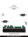
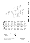
DUAL DISCRETE MICROPHONE PREAMPLIFIER AND EQUALISER ® AUDIO DEVELOPMENTS ® OWNERS HANDBOOK ® AUDIO DEVELOPMENTS Designed in England and assembled in the UK and USA to Trident Audio’s strict specifications, Trident Audio is manufactured under the direction of and distributed exclusively by: PMI AUDIO GROUP USA: 1845 W. 169th Street Gardena, CA 90247 toll free: 877-563-6335 fax: 310-323-0900 UK: Unit 4 Minerva Court Woodland Industrial Estate Torquay, TQ2 7BD tel: +44 (0)1803-612700 fax: +44 (0)1803-612009 email: [email protected] www.trident-audio.com Written by Professor Malcolm Toft TRIDENT AUDIO DEVELOPMENTS ®, TRIDENT AUDIO ®, TRIDENT SERIES ® and ARANGE ® are all registered trademarks of PMI Audio Group Important Safety Information CAUTION CAUTION: TO REDUCE THE RISK OF ELECTRIC SHOCK, DO NOT REMOVE COVER. NO USER-SERVICEABLE PARTS INSIDE. REFER SERVICING TO QUALIFIED SERVICE PERSONNEL. The lightning flash with arrowhead symbol, within an equilateral triangle, is intended to alert the user to the presence of uninsulated “dangerous voltage” within the product’s enclosure that may be of sufficient magnitude to constitute a risk of electric shock to persons. The exclamation point within an equilateral triangle is intended to alert the user to the presence of important operating and maintenance (servicing) instructions in the literature accompanying the appliance. WARNING: TO AVOID FIRE OR ELECTRIC SHOCK HAZARD, DO NOT EXPOSE THIS APPARATUS TO WATER, RAIN OR MOISTURE. NOTE — This apparatus does not exceed the Class A/Class B (whichever is applicable) limits for radio noise emissions from digital apparatus as set out in the radio interference regulations of the Canadian Department of Communications. . ATTENTION — Le présent appareil numérique n’émet pas de bruits radioélectriques dépassant las limites applicables aux appareils numériques de class A/de class B (selon le cas) prescrites dans le réglement sur le brouillage radioélectrique édicté par les ministere des communications du Canada. These limits are designed to provide reasonable protection against harmful interference in a commercial/residential installation respectively. This equipment generates, uses, and can radiate radio frequency energy and, if not installed and used in accordance with the instruction manual, may cause harmful interference to radio communications. There is no guarantee that interference will not occur in a particular installation. If this equipment does cause interference to radio or television equipment reception, which can be determined by turning the equipment off and on, the user is encouraged to try to correct the interference by any combination of the following measures: (1) Relocate or reorient the receiving antenna (2) Increase the separation between the equipment and the receiver (3) Plug the equipment into an outlet on a circuit different from that to which the receiver is connected (4) Consult your dealer or experienced radio/television technician for additional assistance. CAUTION — Changes or modifications to this equipment not expressly approved by the party responsible for compliance could void the user's authority to operate this equipment. Important Safety Instructions 1. Read these instructions. 2. Keep these instructions. 3. Heed all warnings. 4. Follow all instructions. 5. Do not use this apparatus near water. Do not expose to drips or splashes. Do not place any objects filled with liquids, such as vases, on the apparatus. 6. Clean only with dry cloth. 7. Do not block any ventilation openings. Do not install this apparatus in a confined space such as a book case or similar unit. Install only in racks designed for the purpose and in accordance with manufacturers’ instructions. 8. Do not install near any heat sources such as radiators, heat registers, stoves, or other apparatus (including amplifiers) that produce heat. 9. Do not defeat the safety purpose of the polarized or grounding-type plug. A polarized plug has two blades with one wider than the other. A grounding-type plug has two blades and a third grounding prong. The wide blade or the third prong are provided for your safety. If the provided plug does not fit into your outlet, consult an electrician for replacement of the obsolete outlet. 10. Protect the power cord from being walked on or pinched particularly at plugs, convenience receptacles, and the point where they exit from the apparatus. 11. Only use attachments and accessories specified by the manufacturer. 12. Use only with a cart, stand, tripod, bracket, or table specified by the manufacturer, or sold with the apparatus. When a cart is used, use caution when moving the cart/apparatus combination to avoid injury from tip-over. 13. Unplug this apparatus during lightning storms or when unused for long periods of time. 14. Refer all servicing to qualified service personnel. Servicing is required when the apparatus has been damaged in any way, such as power-supply cord or plug is damaged, liquid has been spilled or objects have fallen into the apparatus, the apparatus has been exposed to rain or moisture, does not operate normally, or has been dropped. 15. Apparatus designed with Class-I construction must be connected to a mains socket outlet with a protective earthing connection (the third grounding prong). 16. This apparatus may be equipped with a single-pole, rocker-style AC mains power switch. If so this switch is located on the front panel and should remain readily accessible to the user. 17. The manufacturer reserves the right to change the technical specification of the product without prior notice. 3 Statement of RoHS Compliance Statement of WEEE Policy PMI Audio Group manufactures complete electronic products which are covered by the European Union’s “Removal of Hazardous Substances” directive 2002/95/EC (RoHS). This directive seeks to eliminate toxic substances from the manufacturing process, such that when equipment is disposed of at the end of its life cycle, the materials it contains do not contaminate the environment and pose health risks. Banned substances are lead, mercury, cadmium, hexavalent chromium, polybrominated biphenyls (PBB) and poly-brominated diphenyl ethers (PBDE). Lead is used together with tin in solder connections to reduce the melting point of solder. Lead-free solder requires higher soldering temperatures which in turn places greater thermal stress on components. PMI Audio Group manufactures many complete electronic products which are covered by the European Union’s “Waste Electric and Electronic Equipment” directive 2002/96/EC (WEEE). This directive seeks to ensure that waste electric and electronic equipment is disposed of in an environmentally responsible manner, at the end of its life cycle. PMI Audio Group takes seriously its obligations under this directive to take back WEEEaffected products and, from 13th August 2005, will mark all such products with the crossed-out wheeled bin symbol. RoHS COMPLIANT Pb PMI Audio Group takes seriously its obligations under the RoHS directive and insists that its factories use only components that are certified RoHS compliant, as well as lead-free solder. In a very few cases the necessary components may not yet be available to the world market but we work continuously to eliminate any such exceptions at the earliest opportunity. Our printed Circuit Boards (PCB’s) and all soldered joints have been leadfree since 2005. 4 Business to Business products: PMI Audio Group will cost-neutrally take back WEEE-affected electric and electronic equipment in this category, from 1st January 2006. PMI Audio Group will work with disposal and recycling partners working within the EU. The waste electric and electronic equipment can then be turned over to a disposal and recycling companies in the countries concerned. Business to Customer products: emerging electric and electronic equipment will be disposed of by local authorities' collection systems. Dual Use products: this equipment will be disposed of by local authorities' collection systems. CONTENTS About the “A” Range 6 Product Description 7 Connecting the Unit 7 Input Section 8 Equaliser 9 Insert Bypass and Insert Pre / Post 10 Trouble Shooting 11 Technical S 12 5 ABOUT THE “A” Range Trident Recording Studio’s started operations back in the 1960's as a recording studio. Many things came out of the Recording Studio that led to what Trident Audio Developments is today. Trident Recording Studios recorded legendary bands like David Bowie, The Beatles, James Taylor, Queen, Supertramp, Mott The Hoople, Bad Company, Free, Rush, Elton John, Manfed Mann, T-Rex and so many more, we simply do not have the space to list them all here. These recordings were done by incredible recording engineers like Roy Thomas Baker, Ken Scott, Tony Platt, Tony Visconti, Adam Moseley, Dave Hentschel, and many others. Trident Studios was the place known by the very famous bands as the place to record in London. Trident studios was the first studio to acquire the first ever 8 Track from Ampex. No one in London had an 8 Track…not even EMI. When Trident got its first 16 track recorder, they decided to buy a new recording console but simply could not find any commercially available console to do 16 track recording with the feature set they needed. It was decided by the powers to be at Trident that between the recording engineers, and the technical staff under the direction of Barry Porter, Trident would attempt to build their own custom console. The first console was designed purely for Trident Studios and was designated the 'A' Series. It was hand built to the need of the facilities and designed to be ergonomic. In those days, the integrated circuit (i.c.) had not been invented, so all of the circuits used individual transistors (known as discrete design). This and the use of inductors in the lower and upper mid equaliser sections are said to account for much of the unique sound of the 'A' Series. From this first successful design was borne Trident Audio Developments Ltd, which went on to become a leading manufacturer of music recording consoles. One of the company's earliest advertising slogans was 'designed by recording engineers for recording engineers'. This became a key component of what made the 'Trident Sound' unique. As a recording engineer rather than an electronics engineer, Trident Audio Developments was designed by the engineers ears, rather than a text book of electronic design, and it is this, coupled with over thirty years experience that has enabled Trident Audio Developments to develop its own 'philosophy of sound' that is Trident's trademark. The “A” Series eventually led to the development of the “A“ Range Console, which became the console everyone wanted to work and record on. The “A“ Range was quickly labeled as the best sounding console ever. Today, PMI Audio has created a two channel version of the A Range Mic Preamplifer and the “A“ Range 4 band EQ of the console and housed it in a 2U 19” Rack unit. This new dual channel unit is an exact replica of the original all discrete transistor circuitry, and it faithfully follows the original electronic circuit design to the absolute degree. So much so that it has taken three years of circuit analysis and testing by PMI Audio’s designers and many of its former engineers who undertook the mammoth task of recreating the original’s designs. Needless to say, Trident Audio Developments and PMI Audio are extremely pleased and proud to offer this unique piece of recording history. There were only thirteen A Range consoles ever built back in the 1970’s, and almost all of them have been rebuilt and are still in use today, despite being nearly forty years old. This says a lot about the heritage of these iconic items of recording equipment and the artists that have used them. We hope you will enjoy the A Range as much as we have enjoyed designing it. 6 PRODUCT DESCRIPTION O A RANGE The A-Range ® is a 2-channel rack-mountable version of the legendary Trident 'A' Range console. Comprising two independent channels, each with a microphone/line amplifier and four band equaliser, it is designed to process incoming signals from a microphone or line level instrument and output to a recording device, such as a digital audio workstation or analog multi-track tape recorder. Mains powered, with 48 volt phantom power independently switchable for the two channels, the A-Range ® operates as a complete stand-alone unit. In keeping with its mixing console heritage, each 'channel strip' of this rack unit features insert points (switchable pre/post EQ and with bypass), phase reverse (which operates on both microphone and line inputs) and an output level control with peak signal indication. All inputs and outputs are balanced so that maximum signal integrity and high output levels are assured with minimum distortion. A useful additional facility when using it as a stand-alone unit is the inclusion of LED peak level indicators at key points in the signal chain. These are located: directly after the input amplifiers (microphone and line), after the equaliser section and after the main output amplifier. This ensures that the signal is accurately monitored and matched at all stages in the signal chain. The A-Range ® rack will add its own signature to any programme material, whether using just the discrete transistor microphone and line input preamplifiers or the unique and versatile equaliser sections. CONNECTING THE UNIT TRIDENT AUDIO DEVELOPMENTS ® CAUTION RISQUE DE CHOC ELECTRIQUE NE PAS OUVRIR TRIDENT ® ENSURE MAINS VOLTAGE AND FUSE RATINGS ARE CORRECT BEFORE CONNECTING MAINS POWER. THIS APPARATUS MUST BE EARTHED BY THE POWER CORD. NO USER SERVICEABLE PARTS REFER SERVICING TO QUALIFIED PERSONNEL. DUAL CHANNEL DISCRETE MIC AMPLIFIER AND EQUALISER EN55103 EN60065 A RANGE Distributed Exclusively by PMI Audio Group Gardena, California 90247 USA www.trident-audio.com Designed in England Assembled in the USA to Trident Audio’s strict specifications TRIDENT SERIES ® The rear panel of the unit provides both XLR and ¼" jack inputs for the line input and output of each channel while a separate XLR is provided for the microphone input. The insert sends and returns are ¼" jacks. The XLR connectors use the standard industry convention of pin 1 ground, pin 2 positive and pin 3 negative. The jacks are tip-positive, ring-negative and sleeve ground. For unbalanced use, connect the ring to the sleeve. 7 When connecting a microphone, set the 'Input Level' control for each channel to minimum, with the phantom power +48V switch off (LED extinguished). The microphone input is designed to accept the signal from low impedance, balanced microphones of either dynamic, ribbon or condenser types. The line input is designed to accept balanced or unbalanced, line level audio signals. Mic or Line input is selected via the front panel 'Line' switch (LED lights for 'Line'). The outputs from each channel are low impedance and designed to operate with long cable runs without signal degradation. A standard IEC mains inlet is provided for AC mains power. Operating voltage of either 120 or 240 volts is selectable by rotating the fuse holder incorporated into the mains inlet socket. INPUT SECTION The input section of the A-Range ® rack consists of a very high quality transformer-coupled discrete microphone amplifier and transformer-coupled discrete line amplifier designed specifically for professional audio applications. The microphone and line transformers are custom designed to the exact original Trident A-Range ® specifications. The microphone amplifier is designed to handle signal levels from -60dBu to as high as +10dBu without needing a separate pad switch. The 15-position combined mic/line gain switch is calibrated in accurate 5dB steps to provide precise matching of either microphone or line level signals. In conjunction with the 'Output' level control, very fine adjustment of signal level is achievable. The preamplifier exhibits very low noise while maintaining extremely fast transient response and a frequency response that extends beyond 40kHz. Naturally, best results are achieved when using a high quality condenser microphone. The microphone amplifier will also bring out the best in dynamic and ribbon microphones. When connecting a microphone to the input of the unit, set the 'Input Level' rotary switch to its minimum ('0') position and the 'Output' level control to its '0' position. The 'Line' switch should not be depressed. If required, engage the '+48V' phantom power switch while the 'Input Level' control is at minimum. The associated LED will show that phantom power is present. Allow up to 30 seconds for the microphone to reach normal operating level and advance the 'Input Level' control until a suitable level is achieved at the output of the unit. The 'O/P peak' LED signal indicator at the output stage of the circuit is designed to light when a signal level of +15dBu occurs at the output stage. This provides plenty of overload margin as the A-Range ® is capable of very high output levels (up to +26dBu) into a balanced load. However, by setting the level as described above, adequate headroom is maintained and there should be no danger of overloading following equipment. The phase (polarity) reverse switch is employed when phase interference occurs between multiple microphones. Such interference results when microphones, at various placements, pick up the same sound source at slightly different times. When the output of the microphones combine, cancellation occurs at certain frequencies. This effect is known as comb filtering. Switching the polarity on one microphone may serve to minimise this effect. When using a line level signal, the 'Line' switch should be depressed (LED illuminates) and the 'Input Level' control switched to '0'. +48V phantom power should never be selected in the 'Line' mode as this can cause a loud noise when the phase reverse switch is operated. In this position with the 8 'Output' level control also set to '0', the unit is designed to give unity or 0dB gain. The line input gain can be adjusted in accurate 5dB steps in the same way as the microphone amplifier. However, the line input adjustment only operates between the +10 and -10 positions of the switch. In all other positions, the line input reverts to zero or 'unity' gain. EQUALISER The legendary A-Range ® equaliser is a unique and amazingly musical sounding equaliser - owing much to its all-discrete transistor circuitry and the use of inductors in the lower and upper mid range. The mid EQ sections are 'peaking', while the high and low range sections are 'shelving'. Each of the four bands is rotary-switch-selectable to any one of four frequencies, while individual push buttons engage the three high pass and three low pass filters. A novel feature of the original A-Range ® console and incorporated in this unit, is the use of longthrow faders for level adjustment, rather than rotary potentiometers. These faders feature a useful centre dedent at mid travel to denote zero boost or cut of the selected frequency. The use of faders makes it very easy to see not only when equalisation is being applied, but also the amount. A notable difference in the operation of the sliders on the rack unit, versus the original A-Range ® console, is one of physical orientation: the old console sliders move vertically, while the rack unit sliders move horizontally. Accordingly, on the consoles, the slider moved up to 'boost' and down to 'cut', whereas the rack version moves right to boost and left to cut. For most users, the layout adopted here will seem logical. However for some engineers, accustomed to working with old A-Range ® modules mounted sideways, this will seem backwards. This particular aspect of the design was the subject of much consideration but in the end, it was decided that the rack unit should have a more conventional 'right to boost, left to cut'. For those not familiar with the difference between a shelving and peaking equaliser, the differences are as follows. A shelving equaliser boosts (or attenuates) all frequencies equally, above or below a certain point. The frequency specified for a shelving equaliser circuit is usually at the point where it effectively reaches its 'shelf' state. A 'high shelf' EQ boosts/cuts high frequencies and a 'low shelf' type boosts/cuts low frequencies. This type of circuit is very popular in hi-fi systems but is also actually highly musical, when applied in a recording environment. In contrast, a peaking equaliser is one that, as its name implies, has a centre frequency that is boosted or attenuated more than others. The frequency range over which it reaches its peak and then falls down is known as the bandwidth (or 'Q'). Because this type of design reaches a peak and then falls away, it is possible with this type of circuit to 'home in' on a particular area of frequencies and make adjustments without affecting those around them. This can be particularly useful when working with instruments such as bass guitars and snare drums. By incorporating both shelving and peaking equalisers into the design of the A-Range ®, it is possible to get the best of both types of design. Operating the Equaliser Set the 'Input Level' in accordance with the procedures detailed in the 'Input Section' section of this manual. Begin with all boost/cut faders set to their mid way ('0') positions. Adjust the low and high mid frequency controls to their minimum positions (fully clockwise). The high and low pass filter switches should be in their out positions. Set the frequency select switches controlling the high and low shelving sections, to 150Hz and 12kHz respectively. Lastly, set the 'EQ' switch to the 'IN' position (the associated LED will illuminate). 9 Moving any one or more of the four faders next to their associated frequency select switches to the right of centre, will result in the chosen frequency being increased in level. Moving the faders to the left of centre will result in the chosen frequency being attenuated. Operating the frequency select switch in the high section (8kHz to 15kHz shelving) will introduce a subtle change of emphasis of the high frequencies being affected. Operating the frequency select switch in the upper mid section (3kHz to 9kHz peaking) will introduce a distinct difference according to the frequency selected, since it is now peaking rather than shelving and also due to the characteristics of the inductor-based topology. Operating the frequency select switch in the 'lower mid' section, 250Hz - 2kHz peaking, will also introduce a distinct difference according to the frequency selected, again because of its peaking nature and the use of inductors in this part of the circuit. Operating the frequency select switch in the low section, 80Hz - 150Hz shelving, will introduce an effective change of emphasis to the low frequencies, according to the switch setting. Finally, the three shelving 'low-pass' and 'high-pass' filter sections are employed to introduce a rolloff of either high frequencies or low frequencies respectively, according to which of the three push buttons are selected in each section. The high-pass filters are useful for the minimization of extraneous low frequency 'rumble' caused, for example, by someone's feet moving about near a microphone stand, nearby traffic noise, AC systems, etc. Additionally, a high-pass filter can be used effectively during recording to reduce the accumulation of low frequency sounds that can adversely affect a mix. The three high-pass corner frequencies are 25Hz, 50Hz and 100Hz. The low-pass filters are used to minimize high frequency noise that may cause 'harshness' in a vocal, or to tame the output of a violin or guitar amplifier, etc. Low-pass filtering is often employed on kick and snare drums and bass guitars, as well as a means of reducing 'hiss'. The three low-pass filter frequencies on the A-Range ® are 9k, 12k and 15k. Filters can also be used in combination for greater effect. The amount of boost (accentuation) or cut (attenuation) that is applied to the audio signal is entirely dependent on the programme content and it is not our intention to advise on this. Application of equalisation is a very subjective matter and is best learned by trial and error. The equaliser bypass switch 'EQ IN' is a useful facility for comparing the signal before and after equalisation. INSERT IN AND INSERT PRE These two switches are very useful when the unit is used as two independent 'channel strips'. The 'pre/post' facility allows the user to choose at which point an external signal processing device (such as a compressor/limiter) is inserted into the signal chain and the 'bypass' facility makes it possible to compare the unprocessed signal with the processed signal by the touch of a single button. The 'Insert In' button enables the unbalanced Insert Send and Return points, which are accessible via ¼" jacks on the rear of the unit. When 'Pre EQ' is selected, the 'Insert' point is located between the output of the Mic/Line amplifier and the input of the equaliser. In 'post' mode, the 'Insert' point is instead placed after the equaliser section and before the final output amplifier. The ability to bypass the Insert makes it easy to compare the signal with and without the external processing device, with no need to unplug it from the Send and Return jacks on the rear of the unit. Without this function it would either be necessary to disconnect the external processor, or operate its controls separately. Because it is still connected (even when bypassed), it is possible adjust the external device (eg: to set the correct level) before it is switched into the A-Range ® signal path. 10 TROUBLE SHOOTING 1) No Power. Ensure the unit is selected for the correct mains voltage via the selector incorporated in the mains inlet socket on the back of the unit. Check the fuse (also in the mains inlet socket) if the unit has been powered with the wrong voltage. Check there is a mains supply reaching the unit. 2) The microphone doesn't work. Is it connected to the correct input on the back of the unit? Is the '+48V' phantom power switched on (for condenser microphones)? Is the input selected to Mic ('LINE' switch not depressed)? Make sure the 'Input Level' rotary switch is turned up. 3) The line input doesn't work. Is it connected to the correct input on the back of the unit? Is the input selected to 'LINE' (LED illuminated)? Make sure the 'Input Level' rotary switch is set to '0'. 4) The equaliser doesn't work. Is the 'EQ' switch selected to 'IN' (LED illuminated)? 11 TECHNICAL SPECIFICATIONS Input Impedance: Microphone: Line: 600 ohm transformer balanced 10k ohm transformer balanced Output Impedance: <100 ohm transformer balanced Gain: Microphone: Line: 0dB to +60dB -10dB to +10dB Noise: Microphone: Line: <-126dBu ref 150 ohm (20Hz-20kHz) <-85dBu (EQ In, 20Hz-20kHz) Maximum Levels: Mic Input: Line Input: +24dBu at all frequencies +24dBu at all frequencies Distortion: Mic Input: Line Input: <0.05% T.H.D. (-50dBu input, +4dBu output) <0.05% T.H.D. (+4dBu input, +4dBu output) Frequency Response: Mic Input: Line Input ±1dB 20Hz to 20kHz ±1dB 20Hz to 20kHz Nominal Operating Level: +4dBu Peak LED Threshold: +15dBu In accordance with our policy of continuing product improvement, we reserve the right to alter specifications without prior notice. 12 Notes 13 Limited Warranty THIS PRODUCT IS FOR PROFESSIONAL USE ONLY PMI Audio Group warrants that all products will be free from defects in material or workmanship: A: For a period of one (1) year from the date of purchase (hereinafter the labor warranty period). PMI Audio Group will repair or replace this Product if determined to be defective. After the expiration of the labor warranty period, the Purchaser must pay labor charges. B: In addition, PMI Audio Group will supply, at no charge, replacements for defective parts for a period of one (1) year from the date of purchase. During the labor warranty period, to repair the Product, the Purchaser must return the defective Product, freight prepaid, or deliver it to a PMI Audio Group Service Center. The Product to be repaired is to be returned in either its original carton or a similar package affording an equal degree of protection. PMI Audio Group will return the repaired Product freight prepaid to the Purchaser. PMI Audio Group is not obligated to provide the Purchaser with a substitute unit during the warranty period or at any time. Conditions of Warranty 1. Notification of claims: Warranty Service: If Purchaser discovers that the Product has proven defective in material or workmanship, then written notice with a full explanation of the claim shall be given promptly by the Purchaser to PMI but all claims for warranty service must be made within the warranty period. If after investigation PMI determines that the reported problem was not covered by the warranty, Purchaser shall pay PMI for the cost of investigating the problem at it's the prevailing time-and-materials rate. No repair or replacement by Purchaser of any Product or part thereof shall extend the warranty period as to the entire Product. The specific warranty on the repaired part only shall be in effect for a period of ninety (90) days following repair or replacement of that part or the remaining period of the Product warranty, whichever is greater. 2. Exclusive Remedy: Acceptance: Purchaser’s exclusive remedy and PMI’s sole obligation is to supply (and pay for) all labor necessary to repair any product found to be defective within the warranty period and to supply, at no extra charge, new or rebuilt replacements for defective parts. If repair or replacement fails to remedy the defect, then and only in such an event, shall PMI exchange to Purchaser a new or reconditioned unit. Purchaser’s failure to make a claim as provided in paragraph 1 above or continued use of the product shall constitute an unqualified acceptance of such Product and a waiver by Purchaser of all claims thereto. 3. Exceptions to Limited Warranty: PMI shall have no liability or obligation to Purchaser with respect to any Product subjected to abuse, negligence, accident, modification, failure of the end-user to follow the operating and maintenance procedures outlined in the users manual, attempted repair by non-qualified personnel, operation of the unit outside of the published environmental and electrical parameters, or if such Product’s original identification (trademark, serial number) markings have been defaced, altered, or removed. PMI excludes from warranty coverage, Products sold AS IS and/or WITH ALL FAULTS and excludes used products which have not been sold by PMI to the purchaser. PMI also excludes from warranty coverage consumables such as fuses and batteries, tubes, etc . 4. Proof of Purchase: The dealer’s dated bill of sale must be retained as evidence of the date of purchase and to establish warranty eligibility. 5. Grey Market: All warranties apply only to PMI Audio Group Products purchased and used in the USA, and to PMI Audio UK Products purchased and used in the UK, EU and all other countries outside of the USA. All warranties apply only to PMI Audio Group/PMI Audio UK Products originally purchased from an authorized PMI Audio Group/PMI Audio UK dealer. PMI Audio Group/PMI Audio UK Product that was not purchased through an authorized and legitimate sales channel is considered "Grey Market". Warranties for PMI Audio Group/PMI Audio UK Products purchased outside their respective territories will be covered by the PMI Audio Group/PMI Audio UK Importer for that specific country or region. Products originally sold to the USA market and consequently resold overseas forfeit their warranty as do PMI Audio UK Products sold outside of the UK and Europe. American PMI Audio Group Dealers are expressly forbidden to export PMI Audio Group Products and PMI Audio UK Distributors and Dealers are expressly forbidden to export to North, South, Central and Latin America. "Grey Market" purchases are not covered by any warranty. In the case that a PMI Audio Group/PMI Audio UK Product must be returned to the factory from outside its respective territory, customer shall adhere to specific shipping, customs, and commercial invoicing instructions given with the Return Authorization as PMI Audio Group/PMI Audio UK will not be responsible for transportation costs or customs fees related to any importation or re-exportation charges whatsoever. Disclaimer of Warranty EXCEPT FOR THE FOREGOING WARRANTIES, PMI HEREBY DISCLAIMS AND EXCLUDES OTHER WARRANTIES, EXPRESS OR LIMITED, INCLUDING BUT NOT LIMITED TO ANY/OR ALL IMPLIED WARRANTIES OF MERCHANTABILITY, FITNESS FOR A PARTICULAR PURPOSE AND/OR ANY WARRANTY WITH REGARD TO ANY CLAIM OF INFRINGEMENT THAT MAY BE PROVED IN SECTION 2-312(12) OF THE UNIFORM COMMERCIAL CODE AND/OR IN ANY COMPARABLE STATE STATUTE. PMI HEREBY DISCLAIMS ANY REPRESENTATIONS OR WARRANTY THAT THE PRODUCT IS COMPATIBLE WITH ANY COMBINATION OF NON-PMI AUDIO PRODUCTS PURCHASER MAY CHOOSE TO CONNECT TO THE PRODUCT. Limitation of Liability THE LIABILITY OF PMI, IF ANY, AND PURCHASER’S SOLE AND EXCLUSIVE REMEDY FOR DAMAGES FOR ANY CLAIM OF ANY KIND WHATSOEVER, REGARDLESS OF THE LEGAL THEORY AND WHETHER ARISING IN TORT OR CONTRACT, SHALL NOT BE GREATER THAN THE ACTUAL PURCHASE PRICE OF THE PRODUCT WITH RESPECT TO WHICH SUCH CLAIM IS MADE. IN NO EVENT SHALL PMI BE LIABLE TO PURCHASER FOR ANY SPECIAL, INDIRECT, INCIDENTAL, OR CONSEQUENTIAL DAMAGES OF ANY KIND INCLUDING, BUT NOT LIMITED TO, COMPENSATION, REIMBURSEMENT OR DAMAGES ON ACCOUNT OF THE LOSS OF PRESENT OR PROSPECTIVE PROFITS OR ANY OTHER REASON WHATSOEVER. Information in this User Guide is subject to change without notice. No part of this User Guide may be reproduced or transmitted in any form or by any means, electronic, mechanical or by any other means, for any purpose, without the express written permission of PMI Audio Group. PMI Audio Group may have trademarks, copyrights or other intellectual property rights covering the subject matter of this User Guide. Except as expressly provided in any written agreement from PMI Audio Group, the furnishing of this User Guide is provided for the sole use of the authorized User (or Service Agent where applicable) and does not give the User any license to use any trademarks, copyrights or other intellectual property of PMI Audio Group. PMI, PMI AUDIO, TED FLETCHER, MEEQUALIZER, STUDIO PROJECTS, JOEMEEK, TOFT AUDIO DESIGNS, CURRENTSENSE, MEEKROPHONE, TRAKPAK and "If it Sounds Right... It is Right" are either registered trademarks or trademarks of PMI Audio Group in the USA and/or other countries. Copyright © 2010 PMI Audio Group. All rights reserved. 14 Owners Registration TO BE COMPLETED AT TIME OF PURCHASE Name _____________________________________________________________________________________ Date of Purchase ______________________________________________________________________________ Model Number _______________________________________________________________________________ Serial Number _______________________________________________________________________________ Dealer’s Name _______________________________________________________________________________ RETAIN FOR YOUR RECORDS PLEASE DISPATCH AND RETURN THE REGISTRATION CARD BELOW TO PMI AUDIO WITHIN 14 DAYS OF PURCHASE Specifications and model numbers are subject to change without notice Product Registration Information Please fill in the sections below and return Name: Address: City: State: Zip Code: Telephone Number: email Address: Model Purchased: Date Purchased: Serial Number: Dealer: Comments: What magazines do you read to inform your buying decision: (check all that apply) 1 1 MIX Electronic Musician 1 1 EQ Sound on Sound 1 Pro Audio Review 1 Recording 1 Pro Sound News 1 Audio MIDI Place Stamp Here Trident Audio Developments® A PMI Audio Group Company 1845 W. 169th Street Gardena, CA 90247 USA Trident Audio Developments® is a Registered Trademarks of PMI Audio Group®