1
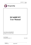
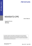
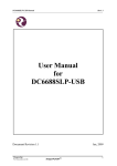
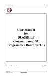
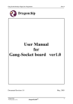
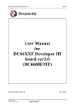
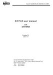
DC6388EMT User Manual
Rev1.1
Dragonchip
DC6388EMT
User Manual
User Manual of DC6388EMT
Emulator for DC6388F Family
User Manual
Document Revision 1.1
Oct, 2014
_____________________________________________________________________________________
1
Dragonchip
TM
DragonFLASH
We bring silicon to life
DC6388EMT User Manual
Rev1.1
Contents
1
INTRODUCTION ............................................................................................................................ 3
1.1 SUPPORTED PRODUCTS ....................................................................................................................... 3
1.2 PACKAGE ............................................................................................................................................ 3
1.3 USEFUL LINKS .................................................................................................................................... 3
2
HARDWARE ..................................................................................................................................... 3
2.1 CONTROL INTERFACE.......................................................................................................................... 3
2.2 IDE CONNECTOR ................................................................................................................................ 4
3
SOFTWARE INSTALLATION ....................................................................................................... 6
3.1 SOURCE CODE TEMPLATE ................................................................................................................... 7
3.2 KEIL PROJECT SETTINGS ..................................................................................................................... 7
4
VIEW MEMORY CONTENT ....................................................................................................... 11
5
LIMITATIONS ............................................................................................................................... 11
6
REVISION HISTORY.................................................................................................................... 12
_____________________________________________________________________________________
2
Dragonchip
TM
DragonFLASH
We bring silicon to life
DC6388EMT User Manual
Rev1.1
1 Introduction
This document briefly describes the details of the development tool ‘Emulator for
DC6388F Family (DC6388EMT)’.
1.1 Supported Products
Part Number
DC6388EMT-FD
Supported Products
DC6388FD
1.2 Package
1)
2)
3)
4)
5)
Emulator
Power Adaptor (5VDC Output)
Mini USB Cable
User Manual
Installation CD
1.3 Useful Links
1) DC6388EMT Emulator
http://www.dragonchip.com/TechDoc/DC6388F/DevTools/EMT.htm
2) DC6388F Technical Website
http://www.dragonchip.com/TechDoc/DC6388.htm
2 Hardware
2.1 Control Interface
USB Port:
- Connect to PC
- Connect to 5V power
adaptor (optional)
ON/OFF Button:
Power ON/OFF
device
Status LED:
Power ON
Debug
Sub Clock LED:
XIN2 Oscillator
status
Main Clock LED:
XIN Oscillator
status
_____________________________________________________________________________________
3
Dragonchip
TM
DragonFLASH
We bring silicon to life
DC6388EMT User Manual
Rev1.1
2.2 IDE Connector
Connect the emulator to target board through the ribbon cable and IDE
Connector. Put a 2.54mm pitch (52P / 64P) box header or pin header on the
target board. The connector pin assignments are listed below:
IDE Connector
(Top View)
1
2
Ribbon Cable
63 64
48-pin package
Connector
Pin No.
1
3
5
7
9
11
13
15
17
19
21
23
25
27
29
31
33
35
37
39
41
43
45
47
49
51
53
55
MCU Pin
No.
12
13
14
15
17
18
21
23
24
25
26
27
28
29
30
31
32
33
34
35
36
-
Pin Name
PE2
PE3
PE4
PE5
PE6
PE7
VSS
VDD
PC1
COM0
COM1
COM2
COM3
SEG0/V3
SEG1/V2
SEG2/V1
SEG3
SEG4
SEG5
SEG6
SEG7
-
Connector
Pin No.
2
4
6
8
10
12
14
16
18
20
22
24
26
28
30
32
34
36
38
40
42
44
46
48
50
52
54
56
MCU Pin
No.
11
10
9
8
7
6
5
4
3
2
1
48
47
46
45
44
43
42
41
40
39
38
37
-
Pin Name
PE1
PE0
PD4/SEG28
PD3/SEG27
PD2/SEG26
PD1/SEG25
PD0/SEG24
PB7/SEG23
PB6/SEG22
PB5/SEG21
PB4/SEG20
PB3/SEG19
PB2/SEG18
PB1/SEG17
PB0/SEG16
PA7/SEG15
PA6/SEG14
PA5/SEG13
PA4/SEG12
PA3/SEG11
PA2/SEG10
PA1/SEG9
PA0/SEG8
-
_____________________________________________________________________________________
4
Dragonchip
TM
DragonFLASH
We bring silicon to life
DC6388EMT User Manual
Rev1.1
57
59
61
63
-
-
58
60
62
64
-
Connector
Pin No.
2
4
6
8
10
12
14
16
18
20
22
24
26
28
30
32
34
36
38
40
42
44
46
48
50
52
54
56
58
60
62
64
MCU Pin
No.
52
51
50
49
48
47
46
45
44
43
42
41
40
39
38
37
36
35
34
33
32
31
30
29
28
27
-
Connector
Pin No.
2
4
6
8
10
12
14
16
18
20
22
24
26
28
MCU Pin
No.
16
15
11
10
9
8
7
6
5
4
3
2
1
64
-
52-pin package
Connector
Pin No.
1
3
5
7
9
11
13
15
17
19
21
23
25
27
29
31
33
35
37
39
41
43
45
47
49
51
53
55
57
59
61
63
MCU Pin
No.
1
2
3
4
6
7
10
12
13
15
16
17
18
19
20
21
22
23
24
25
26
-
Pin Name
PE2
PE3
PE4
PE5
PE6
PE7
VSS
VDD
PC1
COM0
COM1
COM2
COM3
SEG0/V3
SEG1/V2
SEG2/V1
SEG3
SEG4
SEG5
SEG6
SEG7
-
Pin Name
PE1
PE0
PD7/SEG31
PD6/SEG30
PD5/SEG29
PD4/SEG28
PD3/SEG27
PD2/SEG26
PD1/SEG25
PD0/SEG24
PB7/SEG23
PB6/SEG22
PB5/SEG21
PB4/SEG20
PB3/SEG19
PB2/SEG18
PB1/SEG17
PB0/SEG16
PA7/SEG15
PA6/SEG14
PA5/SEG13
PA4/SEG12
PA3/SEG11
PA2/SEG10
PA1/SEG9
PA0/SEG8
-
64-pin package
Connector
Pin No.
1
3
5
7
9
11
13
15
17
19
21
23
25
27
MCU Pin
No.
17
18
19
20
22
23
26
28
29
-
Pin Name
PE2
PE3
PE4
PE5
PE6
PE7
VSS
VDD
PC1
-
Pin Name
PE1
PE0
PD7/SEG39
PD6/SEG38
PD5/SEG37
PD4/SEG36
PD3/SEG35
PD2/SEG34
PD1/SEG33
PD0/SEG32
PB7/SEG31
PB6/SEG30
PB5/SEG29
PB4/SEG28
_____________________________________________________________________________________
5
Dragonchip
TM
DragonFLASH
We bring silicon to life
DC6388EMT User Manual
Rev1.1
29
31
33
35
37
39
41
43
45
47
49
51
53
55
57
59
61
63
35
36
37
38
40
41
42
43
44
45
46
47
48
49
50
51
12
13
SEG0/COM4
SEG1/COM5
SEG2/COM6
SEG3/COM7
SEG4/V3
SEG5/V2
SEG6/V1
SEG7
SEG8
SEG9
SEG10
SEG11
SEG12
SEG13
SEG14
SEG15
PC0
PC2
30
32
34
36
38
40
42
44
46
48
50
52
54
56
58
60
62
64
63
62
61
60
59
58
57
56
55
54
53
52
34
33
32
31
39
14
PB3/SEG27
PB2/SEG26
PB1/SEG25
PB0/SEG24
PA7/SEG23
PA6/SEG22
PA5/SEG21
PA4/SEG20
PA3/SEG19
PA2/SEG18
PA1/SEG17
PA0/SEG16
COM3
COM2
COM1
COM0
V4
PC3
Note:
1) The voltage supply to emulator chip is 3.3V (VDD pin voltage). User should
do emulation at this voltage level only.
2) Backup mode (LVR triggered) would not be supported.
3) Low voltage indicator (LVI) would not be supported.
4) LVD enable pin VDCE would not be supported
5) Programming pin ISPSEL would not be supported
6) Reset pin RSTN would not be supported.
7) XIN, XOUT, XIN2 and XOUT2 would not be supported. Instead, there are
on-board oscillators to supply clocks and the settings can be configured in
DragonICE.
3 Software Installation
Install the following components
1) Keil PK51 Professional Developers Kit (v9.05 or later)
2) Dragonchip development tools package ‘DC_TOOL_Rev2.4.0.exe’ or later:
a. Source Code Template
b. DragonICE Driver
c. Software SLP
Note: After installing the DragonICE driver, connect the emulator to PC USB port,
the driver will be installed automatically. In case the PC fails to locate the driver,
select the driver path “C:\WINDOWS\system32” manually.
_____________________________________________________________________________________
6
Dragonchip
TM
DragonFLASH
We bring silicon to life
DC6388EMT User Manual
Rev1.1
3.1 Source Code Template
This software can help to generate Keil project templates for various products
with all necessary project settings for using emulators. User can either start the
development with the generated source code template or compare the project
settings with their existing Keil project.
3.2 Keil Project Settings
1) Enter ‘Options for Target’
_____________________________________________________________________________________
7
Dragonchip
TM
DragonFLASH
We bring silicon to life
DC6388EMT User Manual
Rev1.1
2) ‘Device’ Tab - Select DC6388 part number from the list.
3) ‘Target’ Tab – Always check the 2 boxes for ROM and XRAM setting.
Note: The Clock frequency in this page is invalid setting. The setting should be
selected in ‘Programming Setting’ instead.
_____________________________________________________________________________________
8
Dragonchip
TM
DragonFLASH
We bring silicon to life
DC6388EMT User Manual
Rev1.1
4) ‘Debug’ Tab - Follow the settings shown below:
5) ‘Utilities’ Tab - Follow the settings shown below:
_____________________________________________________________________________________
9
Dragonchip
TM
DragonFLASH
We bring silicon to life
DC6388EMT User Manual
Rev1.1
6) Click ‘Settings’ in ‘Utilities’ tab to enter Programming Setting. Input relevant
settings for programming the emulator chip and then press ‘OK’.
Select Device
and Clock
Frequency
Select paths of
Firmware files
(All these files
should be put
in the Keil
project folder)
Model (2 bytes) – configure by Custom Info file
Version (2 bytes) – configure by Custom Info file
Checksum (2 bytes) – generate automatically from Program file
7) Choose either ‘Enable XIN2, XOUT2’ for 32.768kHz oscillator or ‘Enable PE6,
PE7’ for I/O usage.
_____________________________________________________________________________________
10
Dragonchip
TM
DragonFLASH
We bring silicon to life
DC6388EMT User Manual
Rev1.1
4 View Memory Content
The memory content can be checked in the Keil Memory Windows during debug.
Memory
Program/ Data Flash
Internal SRAM
Expanded SRAM
SFR
XFR
Size
Up to 31KB
256 bytes
512B
128 bytes
256 bytes
Memory
Type
code
idata
xdata
data
xdata
Start
Address
0x00000
0x00
0x0200
0x80
0x00
End
Address
0x7BFF
0xFF
0x03FF
0xFF
0xFF
Example
C:0x00000
I:0x00
X:0x0200
D:0x80
X:0x0000
5 Limitations
1) Keil IDE: DragonICE does not support these peripheral features.
2) Keil uVision: uv2 or uv3 cannot be supported by DragonICE. After installing
uv4, open and close the project and you will see the option to upgrade the
project to uv4 format (*.uvproj).
3) Voltage Supply: The voltage supply to emulator chip is 3.3V (VDD pin
voltage). User should do emulation at this voltage level only.
4) MCU Peripherals: When the emulator running is stopped in debugging
environment, all the running MCU peripherals (e.g. LCD driver, timer) would
still keep running. Thus, the MCU peripherals would be out of
synchronization with the code instruction.
5) Compile Keil Project: Only compile the code before entering the Keil
debugging environment. Otherwise the emulated flash content may not be
updated and the debug action may not match with the displayed code. For
example,
a) Cursor jumped to a wrong code location in debugger.
b) ‘Step’ instruction wrong executed as ‘Free Run’ instruction.
_____________________________________________________________________________________
11
Dragonchip
TM
DragonFLASH
We bring silicon to life
DC6388EMT User Manual
Rev1.1
6 Revision History
The following table shows the revision history for this document.
Document
Rev No.
1.0
1.1
Issued Date
Sep, 2014
Oct, 2014
Section
1.1
1.3
2.2
Page
Description
First release
Add supported products section
Add useful links section
Add note to IDE Connection
section
Edited by
Reviewed by
Celia Ki
Danny Ho
Celia Ki
Danny Ho
_____________________________________________________________________________________
12
Dragonchip
TM
DragonFLASH
We bring silicon to life
DC6388EMT User Manual
Rev1.1
Copyright Notice
This specification is copyrighted by Dragonchip Ltd. No part of this specification may be
reproduced in any form or means, without the expressed written consent Dragonchip Ltd.
Disclaimer
Dragonchip Ltd. assumes no responsibility for any errors contained herein.
Copyright by Dragonchip Ltd. All Rights Reserved.
Dragonchip Ltd.
TEL: (852) 2776-0111
FAX: (852) 2776-0996
http://www.dragonchip.com
_____________________________________________________________________________________
13
Dragonchip
TM
DragonFLASH
We bring silicon to life