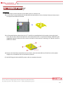
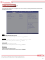
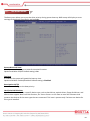
1
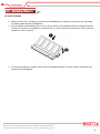
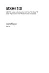
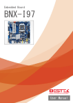
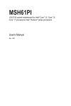
Panel PC PPC-x86P Always at the forefront of innovation User Manual 1 Copyright This publication contains information that is protected by copyright. No part of it may be reproduced in any form or by any means or used to make any transformation adaptation without the prior written permission from the copyright holders. This publication is provided for informational purposes only. The manufacturer makes no representations or warranties with respect to the contents or use of this manual and specifically disclaims any express or implied warranties of merchantability or fitness for any particular purpose. The user will assume the entire risk of the use or the results of the use of this document. Further, the manufacturer reserves the right to revise this publication and make changes to its contents at any time, without obligation to notify any person or entity of such revisions or changes. © 2011. All Rights Reserved. Trademarks All trademarks and registered trademarks of products appearing in this manual are the properties of their respective holders. FCC and DOC Statement on Class A This equipment has been tested and found to comply with the limits for a Class A digital device, pursuant to Part 15 of the FCC rules. These limits are designed to provide reasonable protection against harmful interference when the equipment is operated in a residential installation. This equipment generates, uses, and can radiate radio frequency energy and, if not installed and used in accordance with the instruction manual, may cause harmful interference to radio communications. However, there is no guarantee that interference will not occur in a particular installation. If this equipment does cause harmful interference to radio or television reception, which can be determined by turning the equipment off and on, the user is encouraged to try to correct the interference by one or more of the following measures: Reorient or relocate the receiving antenna. Increase the separation between the equipment and the receiver. Connect the equipment into an outlet on a circuit different from that to which the receiver is connected. Consult the dealer or an experienced radio TV technician for help. Notice: 1. The changes or modifications not expressly approved by the party responsible for compliance could void the user’s authority to operate the equipment. 2. Shielded interface cables must be used in order to comply with the emission limits. 2 Warranty 1. Warranty does not cover damages or failures that are raised from misuse of the product, inability to use the product, unauthorized replacement or alteration of components and product specifications. 2. The warranty is void if the product has been subject to physical abuse, improper installation, modification, accidents or unauthorized repair of the product. 3. Unless otherwise instructed in this user’s manual, the user may not, under any circumstances, attempt to perform service, adjustments or repairs on the product, whether in or out of warranty. It must be returned to the purchase point, factory or authorized service agency for all such work. 4. We will not be liable for any indirect, special, incidental or consequential damages to the product that has been modified or altered. Static Electricity Precautions It is quite easy to inadvertently damage your PC, system board, components or devices even before installing them in your system unit. Static electrical discharge can damage computer components without causing any signs of physical damage. You must take extra care in handling them to ensure against electrostatic build-up. 1. To prevent electrostatic build-up, leave the system board in its anti-static bag until you are ready to install it. 2. Wear an antistatic wrist strap. 3. Do all preparation work on a static-free surface. 4. Hold the device only by its edges. Be careful not to touch any of the components, contacts or connections. 5. Avoid touching the pins or contacts on all modules and connectors. Hold modules or connectors by their ends. Important: Electrostatic discharge (ESD) can damage your processor, disk drive and other components. Perform the upgrade instruction procedures described at an ESD workstation only. If such a station is not available, you can provide some ESD protection by wearing an antistatic wrist strap and attaching it to a metal part of the system chassis. If a wrist strap is unavailable, establish and maintain contact with the system chassis throughout any procedures requiring ESD protection. 3 Safety Measures To avoid damage to the system: • Use the correct AC input voltage range. To reduce the risk of electric shock: • Unplug the power cord before removing the system chassis cover for installation or servicing. After installation or servicing, cover the system chassis before plugging the power cord. Battery: • Danger of explosion if battery incorrectly replaced. • Replace only with the same or equivalent type recommend by the manufacturer. • Dispose of used batteries according to local ordinance. Before Using the System Before using the system, prepare basic system components. If the system comes as a barebone; that is, none of the key components, including processor, memory, and hard drive has been pre-installed as part of your purchase, you will need to at least ensure a compatible counterpart is located and installed. You will also need a few external system peripherals intended for the use of the system, a common pool with at least a keyboard, a mouse, and a monitor is thus suggested. 4 Table of Content Copyright ................................................................................................................................................................ 2 Trademarks ................................................................................................................................................................. 2 FCC and DOC Statement On Class A .......................................................................................................................... 2 Warranty..................................................................................................................................................................... 3 Static Electricity Precautions...................................................................................................................................... 3 Safety Measures ......................................................................................................................................................... 4 Before Using the System Board ................................................................................................................................. 4 Table of Content ......................................................................................................................................................... 5 Chapter 1 General Information 1.1 Main Feature ........................................................................................................................................................... 7 1.2 Specifications ........................................................................................................................................................ 8 1.3 Board Layout ..................................................................................................................................................... 9 1.4 Indications & Features .................................................................................................................................... 10 1.5 Back Panel Connectors ................................................................................................................................... 12 Chapter 2 Jumper Setting 2.1 Before You Begin ...................................................................................................................................... 14 2.2 Precautions ..................................................................................................................................................... 14 2.3 Open Up Memory and Drive Back Cover ......................................................................................................... 15 2.4 Accessing Memory ............................................................................................................................................. 16 2.5 Accessing 2.5” Drive ........................................................................................................................................... 17 2.6 Open Up Expansion Slot Back Cover.................................................................................................................. 18 2.7 Accessing PCIe X4 Slot........................................................................................................................................ 19 2.8 Accessing CPU and Cooler ................................................................................................................................. 20 Chapter 3 Android Software Access 3.1 Turning On The System .................................................................................................................................. 22 3.2 Installing Operating System & Drivers ........................................................................................................... 24 3.3 Understanding LAN Indicators........................................................................................................................... 25 Chapter 4 Android Software Access 4.1 Entering Setup ................................................................................................................................................ 28 4.2 Getting Help .................................................................................................................................................... 28 4.3 Control Keys .................................................................................................................................................... 28 4.4 The Main Menu .............................................................................................................................................. 29 4.5 The Advanced Menu ....................................................................................................................................... 30 4.6 The Chipset Menu........................................................................................................................................... 32 4.7 The Boot Menu ............................................................................................................................................... 34 4.8 The Security Menu.......................................................................................................................................... 36 4.9 The Save & Exit Menu ..................................................................................................................................... 38 Chapter 5 Q & A ................................................................................................................... 38 5 Chapter 1 General Information 6 1.1 Main Feature Performance Panel PC PPC-x86P is a general purpose Panel PC featuring Intel® H77 PCH chipset that supports Intel® Gen-2/3 Core™ desktop processor and two Dual Channel DDR3 SO-DIMM slots up to maximum 16GB DDR3 1066/1333/1600MHz SDRAM with Non-ECC support and integrated HD graphic controller. Every Size Matters From as small as 10.4” easy admission control to some large management console crammed with panes of information, PPC of various sizes are delivered to facilitate all different field sites, in terms of physical touch with machine to be controlled or monitored and display resolutions that are demanded for proper presentation and user experience. Luxurious Input & Output Perfectly designed for industrial applications, PPC-x86P offers a wide variety of input and output, such as HDMI + DisplayPort, Dual Gigabit Ethernet, Audio, 3x RS-232, and user’s choice of optional port as RS-485 or DB15 VGA. For places with only space to hold a display, while no extra space is reserved for a computer controller, PPC-x86P represents a perfect solution with low actuation touch, an optional PCIe slot to expand functions as well as slim DVD for easy maintenance and data reload. List of Key Features Intel® Core™ Gen-2/3 i3/i5/i7 CPU 10.4" ~ 19" Full Range Panel Size 5-Wire Resistive Low Actuation Touch Optional 1x PCIe X4 Slot Optional 802.11 b/g/n Wi-Fi module Optional Slim DVD 7 1.2 Specifications System Display Motherboard BNX-I77 Process Support Intel® Gen-2/3 Core i3, i5, i7, Pentium® , Celeron® Processor Single LGA1155 Socket Chipset Intel® H77 PCH Memory 2x DDR3 1066/1333 DIMM Slots, up to 16GB, Non-ECC/Non-Buffered Memory Module Operation System Android / Linux / Windows Size/Type 10.4” 12.1” 15” 17” 19” Resolution 1024x768 1024x768 1024x768 1280x1024 1280x1024 350 350 300 350 350 311 x 238 x 55 311 x 238 x 55 388 x 335 x 73 388 x 335 x 73 408 x 355 x 73 Brightness(cd/m2) Dimension(mm) Touch interface 5-Wire Resistive Low Actuation Touch Touch stress Drive Bay Saving 50%, 20~25g SATA HDD Slim DVD Connectivity 1* 2.5” HDD Bay None None Option Option Option Option 1: Dual 10/100/1000 Mbps Communication Option 2: Single 10/100/1000 Mbps + Wireless Module (see Options) I/O Expansion Slot Power Environment 1x Power Switch, 1x DC-in Jack, 2x Audio Jacks, 1x HDMI, 1x Display Port, 1x Power LED 1x HDD LED, 2x RJ45 LAN (or 1x with WiFi), 4x USB 3.0, 3x RS232, 1x RS485 (or VGA) None None 1* PCIex4 Input 19Vdc Power-In / 100-240Vac, 50-60Hz Operating Temp. 0oC to 60oC Storage Temp. -20oC to 70oC Humidity 10% to 90% (Operating, non-condensing) VESA Mount 75x75 & 100x100 mm 1* PCIex4 1* PCIex4 8 1.3 System Layout Figure 1.1: System Layout of PPC-x86P 9 1.4 Indicators & Features ►Front View 1. 2. 3. Power Switch with LED 2* optional antenna for wireless module HDD LED ►Rear View 1. 2. 3. 4. CPU cooler fan Access cover for RAM & HDD Access cover for PCIe Card Standard VESA Mount (75x75mm & 100x100mm) 10 ►Side View 1. Single USB 2.0 Port 11 1.5 Back Panel Connectors 1. 2. 3. 4. 5. 6. 7. 8. 9. 10. 11. 12. 13. PCIe Card Retention Bracket PCIe X4 Slot Optional 10/100/1000 LAN Port 2* Audio Jacks 4* USB 3.0 Ports HDMI DisplayPort 10/100/1000 LAN Port 19Vdc Power Input Phoenix Connector RS-232 RS-232 RS-232 RS-485 or VGA as user’s option 12 Chapter 2 Preparation 13 2.1 Before You Begin A stable and clean working environment are essential. Dust and dirt can get into components and cause a malfunction. Use containers to keep small components separated. Adequate lighting and proper tools can prevent you from accidentally damaging the internal components. Most of the procedures that follow require only a few simple tools, including the following: A Philips screwdriver A flat-tipped screwdriver A set of jewelers Screwdrivers A grounding strap An anti-static pad Using your fingers can disconnect most of the connections. It is recommended that you do not use needle-nosed pliers to disconnect connections as these can damage the soft metal or plastic parts of the connectors. Before working on internal components, make sure that the power is off. Ground yourself before touching any internal components, by touching a metal object. Static electricity can damage many of the electronic components. Humid environment tend to have less static electricity than dry environments. A grounding strap is warranted whenever danger of static electricity exists. Computer components and electronic circuit boards can be damaged by discharges of static electricity. Working on the computers that are still connected to a power supply can be extremely dangerous. Follow the guidelines below to avoid damage to your computer or yourself: Always disconnect the unit from the power outlet whenever you are working inside the case. If possible, wear a grounded wrist strap when you are working inside the computer case. Alternatively, discharge any static electricity by touching the bare metal chassis of the unit case, or the bare metal body of any other grounded appliance. Hold electronic circuit boards by the edges only. Never touch the components on the board unless it is necessary to do so. Do not flex or stress the circuit board. Leave all components inside the static-proof packaging that they shipped with until they are ready for installation. Use correct screws and do not over tighten screws. 14 Turn your PPC-x86P upside down, that is, placing the panel side on the table, and find the back cover marked with green color. Remove three screws on the back, one screw on the side, and lift up this back cover to see the memory slot and 2.5” drive bay. Securing all the screws is essential for they would be re-used for the restoration of the back cover, after all preparation procedures are completed. 15 To install SO-DIMM 1. Make sure the “Key” on Memory module and SO-DIMM slot are perfectly matched, and add slowly the RAM module into the SO-DIMM slot. 2. Push the RAM module downwards to seat it firmly. Make sure the RAM module is snapped perfectly by the slot, and the two handles are restored back to “close” position automatically. If not, press the handles to “close” position. 3. To remove the Memory module, please push the handles outwards, and the memory module will be automatically disengaged. 16 Procedures: (1) Turn off the system and open up the back cover as in Section 2.3. (2) Find the four screws fastened on the Hard Drive bracket (blue circles as below). Remove these screws to acquire the Hard Drive bracket. (3) As illustrated below, please have the 2.5” Hard Drive assembled with this bracket, leaving the Hard Drive I/O at either end of the bracket for that the bracket itself is a symmetrical design, and add in the suggested sequence below the four screws enclosed in the accessory screw bag, for a perfect and firm Hard Drive subset. (4) Restore this Hard Drive subset back to the chassis, assure the Hard Drive I/O side face to the power supply unit, and add the four screws back to position. (5) Add SATA signal cable and SATA power cable to complete the work. 17 Turn your PPC-x86P upside down, that is, placing the panel side on the table, and find the back cover marked with green color. Remove three screws on the back, one screw on the side, and lift up this back cover to see the expansion slot. Securing all the screws is essential for they would be re-used for the restoration of the back cover, after all preparation procedures are completed. 18 Procedures: (1) Turn off the system and open up the back cover as in Section 2.6. (2) Find the retention bracket on the slot opening as below (marked with green color). Remove the screw on the bracket (blue circle), and detach this bracket. In case no expansion card is in position, the long PCI bracket will fall out of position now. (3) To add a PCIe expansion card, move the card into the place and make sure the PCIe card bracket tongue is tucked in the cut-out where the retention bracket was placed until it does not move any longer. Watch to align the golden finger of the card and the riser card slot, gently and slowly move the golden finger into the slot firmly. (4) Add the retention bracket and one screw to secure this assembly. (5) Restore the back cover and four screws. 19 Procedures: (1) Turn off the system and find the eight screws that hold the entire large back cover as below. Remove these screws and lift up the large back cover to see all the integrated parts. Please be advised that the large back cover might be snapped by the slim DVD drive if there is any. Watch this corner before the back cover is lifted, especially when an unknown lock-on is occurring. For this particular reason, it is not recommended to open up this large back cover when user’s intention is only around the access of memory, hard drive, or PCIe card, and the other two smaller back covers are better options for such a purpose. (2) In case a processor is already installed, find the four screws that secure the CPU cooler, gently rotate these screws counterclockwisely and diagonally so the heatsink can be disengaged off the processor surface. Change the processor as usual, restore the cooler and cover in the reverse ways. (3) If no processor is installed, add you processor first. Apply proper amount of cooler paste on the processor surface, find the cooler in the product packing, and deploy the cooler. 20 Chapter 3 Operation 21 3.1 Turning On The System Add 19Vdc power to the green phoenix power input connector, making sure polarity has been thoughtfully minded as indicated as Positive and Negative. If a power adaptor is enclosed in the product packing, the AC input range is 100-240Vac. In the case that your AC input is not within this range, though rarely possible in fact, it is not compliant with the power adaptor and you should not plug in the AC power cord. There is chance that users are using their own power adaptor, and it is recommended to make sure the power adaptor matches what is available on your AC power. Should the power adaptor not deliver sufficient amount of power, PPC-x86P may not turn on, or may shut down at any time in use. A power adaptor of at least 90W is considered a good device to use in considerable safety and stably. Turn On the Power In some cases, depending on whether a BIOS setting has been configured to allow immediate power-on upon the delivery of AC power, system might come right up unexpectedly for no particular reason. Please refer to BIOS section for details as to “PWRON After PWR-Fail”. Have you intended to bring it down, simply press once the power switch (located at the front side with yellow circle as above), or press and hold for 4 seconds, to reach that goal. However, in most occasions, without such abrupt event as stated above, simply press once on the Power Switch to turn on the system. 22 Power LED The power switch comes with a built-in LED (to be used as power LED) which shall come lit constant ON at system start. HDD LED The HDD LED can be found next to the power switch, and shall blink in the wake of storage activity, such as SATA drive or CompactFlash. First screen & Optimal BIOS Setting Once the system successfully boots up, it shall activate the panel, disclosing some system information as checkpoints for debugging, thereafter users are encouraged to bring up BIOS setup menu to at least load the optimal BIOS setting, as the first thing to do at power on. Please refer to the BIOS section for substantial details. A USB keyboard is needed for BIOS access. 23 3.2 Installing Operating System & Drivers Confirm the Hard Drive List The system is designed to allow booting from a variety of internal devices, including USB pen drive and SATA drive. Given the tiny footprint and slow performance of USB pen drive, SATA drive is a more popular device to carry operating system and can to be found in the detected drive list, in the section of SATA Configuration. In the event that a particular SATA device is not detected and prompted in the device list, hardly would the system boot from it. Please turn off the system, check or re-apply the SATA cable and SATA power cable to ensure an appropriate connection. Always Mind the SATA Mode SATA controller is embedded in the Intel® H77 PCH, and shall run only in one single SATA mode at a time. Three different modes are available: IDE, AHCI, and RAID. As only one SATA drive is designed for PPC-x86P, RAID mode should never be used. Please ensure that a SATA mode (IDE or ACHI) has been selected for the installation, and always use this particular mode to boot the operating system being installed. Failed to boot the operating system with the correct mode would definitely run into system collapse. While thus disaster occurs, please re-select a SATA mode to try again the advisability of such change, so as to determine the mode being used at installation phase. Procedures to load operating system: (1) (2) (3) (4) (5) (6) (7) (8) (9) Please attach USB DVD drive, or use the built-in Slim-DVD drive if available. Start or restart the system. Press “del” to go to BIOS setup menu. Choose to confirm SATA Controller status. If it is enabled, select a SATA mode and go to (6). If SATA Controller is disabled, bring it up and reboot to allow a re-detection of Hard Drives. Confirm if the Hard Drive has been detected by the prompt of it on the drive list. Scroll and choose to boot from optical device (CD-ROM or DVD-ROM). Save and reboot the system to activate the change and start the installation. Upon reception of messages or instruction from Operating System CD or DVD, please proceed with the rest of the work as installer instructs. Loading Extra Driver Files Some challenges might occur during the installation, as if the issue of no Hard Drive detected, where extra driver files are needed. This is mostly found, when AHCI mode is selected, in operating systems such as Windows-XP, where a USB floppy drive loaded with SATA driver should be prepared and attached on USB port and, at the prompt of such a message, please press “F6” key while being asked to do so, to allow the installer integrate the driver file from floppy drive. Windows-7 (better with SP1) or above apparently do not seem to come with such an issue against the onboard H77 SATA Controller, and hence no extra driver should be needed. On completion of the installation of operating system such as Microsoft Windows, please find the driver CD in the enclosed accessory bag and proceed with driver files installation in the sequence as: INF (Chipset), VGA, LAN, Audio, USB 3.0, ME, and Touch Screen. If some driver updates are available by Windows Update, please accept the updates when prompted. 24 3.3 Understanding LAN Indicators Activity LED The left LED is LAN Port Activity LED, with three different indication status: (1) Constant Yellow: Network is connected. (2) Blinking Yellow: Network activity is on-going. (3) Off: Network is not connected. LAN Speed LED The right LED is LAN Port Speed LED, with three different speeds: (1) Amber: 1000 Speed (2) Green: 100 Speed (3) Off: 10 Speed. Summary Table LED RJ45 NIC Linkage (Left Side) RJ45 NIC Mode (Right Side) Color Yellow Yellow Off Amber Green Off State On Blinking Off On On Off Description LAN linked LAN accessing No LAN linked Gigabit mode 100M mode 10M mode 25 Chapter 4 BIOS Setup 26 About the BIOS The BIOS (Basic Input and Output System) Setup program is a menu driven utility that enables you to make changes to the system configuration and tailor your system to suit your individual work needs. It is a ROM-based configuration utility that displays the system’s configuration status and provides you with a tool to set system parameters. These parameters are stored in non-volatile battery-backed-up CMOS RAM that saves this information even when the power is turned off. When the system is turned back on, the system is configured with the values stored in CMOS. With easy-to-use pull down menus, you can configure such items as: Hard drives, diskette drives, and peripherals Video display type and display options Password protection from unauthorized use Power management features When to Run BIOS This program should be executed under the following conditions: When changing the system configurations. When a configuration error is detected by the system and you are prompted to make changes to the Setup program. When resetting the system clock. When setting the CPU clock speed so that it automatically runs either fast or slow. When redefining the communication ports to prevent any conflicts. When making changes to the Power Management configuration. When changing the password or making other changes to the security setup. Normally, CMOS setup is needed when the system hardware is not consistent with the information contained in the CMOS RAM, whenever the CMOS RAM loses power, or when the system features need to be changed. When to Update BIOS In the event that new features are released and a BIOS update is required, you will need to update your BIOS on your own, with the help of an appropriate guide, a reference tool, and some command files for the job. Please seek for help from your local dealer, or send your request to our technical support department. 27 4.1 Entering Setup When the system is powered on, the BIOS will initiate the Power-On-Self-Test (POST) routines. These routines perform various diagnostic checks. If an error is encountered, the error will be reported in one of two different ways: If the error occurs before the display device is initialized, a series of beeps will be transmitted. If the error occurs after the display device is initialized, the screen will display the error message. Powering on the computer and immediately pressing <Del> allows you to enter Setup. Another way to enter Setup is to power on the computer and wait for the following message during the POST: TO ENTER SETUP BEFORE BOOT PRESS <CTRL-ALT-ESC> OR <DEL> KEY Press the <Del> key or press the <Ctrl>, <Alt>, and <Esc> keys to enter Setup. 4.2 Getting Help The online description of the highlighted setup item is displayed at the right pane of the menu at all time. Press F1 to pop up a small help window that lists all the function keys and its use. To exit the Help Window, press <F1> or <Esc>. 4.3 Control Keys The table below lists all the function keys for the navigation in the BIOS setup menu. Function Key Description Up Arrow Key Move Up Down Arrow Key Move Down Left Arrow Key Move Left Right Arrow Key Move Right Enter Key Select + Key Change value - Key Change Value ESC Exit F1 General Help F2 Previous Values F3 Optimized Defaults F4 Save & Exit Setup To exit the Help Window, press <F1> or <Esc>. 28 4.4 The Main Menu The Main Menu is the first screen that pops up when BIOS Setup Menu is initiated. The main menu allows you to retrieve system information, such as BIOS version, System Memory, and System Date and Time, etc. Figure 4-1: BIOS Setup Utility Main Menu 29 4.5 The Advanced Menu The Advanced Menu allows users to configure most system functions, ACPI Setting, CPU Storage, Network and Hardware Monitoring, etc. DDR over voltage Option available: Enable/Disable. Default setting is Disabled. ACPI Settings Select the highest ACPI sleep state the system will enter, when the suspend button is pressed. Suspend Disable/S1 only (CPU Stop Clock)/S3 only (Suspend to RAM). Default setting is S3 only (Suspend to RAM). CPU Configuration 1. Disclose details of the installed processor 2. Enable/disable CPU hyper-threading, and Intel® Virtualization Technology. SATA Configuration 1. Configure SATA mode (Disable, IDE, AHCI, and RAID). 2. Configure SATA Controller (Disable, Enhanced, Compatible). 3. Disclose the status of all detected SATA devices 30 Intel(R) Raid Start Technology Enable/Disable the Intel Rapid Star Technology (IRSTe) function. The IRSTe enables your system to get up and running faster from even deepest sleep, saving time and power consumption. Option available: Enable/Disabled. Default setting is Disabled. H/W Monitor Configure FAN Setting: 1. CPU/System FAN Fail Detect: Default is Enabled. 2. CPU/System SMART FAN Control: Default is Enabled. 3. SYS FSN Type: 3 Pin Intel(R) Smart Connect Technology Enables or Disables Intel Smart Connect Technology. (default: Disabled) Network Stack Disables or enables booting from the network to install a GPT format OS, such us installing the OS from the Windows Deployment Services server. (Default: Disable Link) CPU PPM Configuration 1. EIST (Enhanced Intel SpeedStep Technology) Conventional Intel SpeedStep Technology switches both voltage and frequency in tandem between high And low levels in response to processor load. Options available: Enable/Disabled. Default setting is Enabled. 2. Turbo Mode When this feature is enabled, the processor can dynamically overclock one or two of its four processing Cores to improve performance with applications that are not multi-threaded or optimizes for quad-core Process. 3. CPU C3/C6 Report Allow you to determine whether to let the CPU enter C3/C6 mode in system halt state. When enabled, the CPU core frequency and voltage will be reduced during system halt state to decrease power consumption. The C3/C6 state is a more enhanced power-saving state than C1. Options available: Enabled/Disabled. Default setting is Enabled. Default setting C3 is Enabled. Default setting C6 is Enabled. 31 4.6 The Chipset Menu The Chipset Menu allows users to configure Intel® H77 PCH feature, including Audio Controller, LAN controller, and LVDS control function. Azalia Enable/Disable onboard audio controller. Options available: Auto/Enabled/Disabled. Default setting is Enabled. Verb Table Define the Verb Table. Mode A does not support DMIC. Mode B supports DMIC. Options available: Mode A/Mode B. Default setting is Mode A. Onboard LAN Enable/Disable onboard LAN controller. Options available: Enabled/Disabled. Default setting is Enabled. ERP Support Enable/Disable Erp support function. Options available: Enabled/Disabled. Default setting is Disabled. 32 Restore AC Power Loss This option provides user to set the mode of operation if an AC / power loss occurs. Power On: System power state when AC cord is re-plugged. Power Off: Do not power on system when AC power is back. Last State: Set system to the last sate when AC power is removed. Options available: Power On/Power Off/Last State. Default setting is Power Off. LVDS Control function Enable/Disable LVDS control function. Options available: Enabled/Disabled. Default setting is Enabled. 33 4.7 The Boot Menu The Boot menu allows you to set the drive priority during system boot-up. BIOS setup will display an error message if the drive(s) specified is not bootable. Bootup NumLock State Allows you to select power-on state for NumLock function. Options available: On/Off. Default setting is On. Fast Boot If enabled, the system will speed the boot up time. Options available: Enabled/Disabled. Default setting is Disabled. Boot Option #1/2/3 Press Enter to configure the boot priority. Hard Drive BBS Priorities Specifies the boot order for a specific device type, such as hard drives, optical drives, floppy disk drives, and devices that support Boot from LAN function, etc. Press <Enter> on this item to enter the submenu that presents the devices of the same type that are connected. This item is present only if at least one device for this type is installed. 34 CSM parameters Launch CSM Enables or disables UEFI CSM (Compatibility Support Module) to support a legacy PC boot process. 1. Enabled: Enables UEFI CSM. (Default) 2. Disabled: Disables UEFI CSM and supports UEFI BIOS boot process only. Boot option filter Allows you to select which type of operating system to boot. 1. UEFI and Legacy: Allows booting from operating systems that support legacy option ROM or UEFI option ROM. (Default) 2. Legacy only: Allows booting from operating systems that only support legacy Option ROM. 3. UEFI only: Allows booting from operating systems that only support UEFI Option ROM. This item is configurable only when Launch CSM is set to Enabled. Launch PXE OpROM policy Allows you to select whether to enable the UEFI or legacy option ROM for the LAN controller. 1. Do not launch: Disables option ROM. (Default) 2. Legacy only: Enables legacy Option ROM only. 3. UEFI only: Enables UEFI Option ROM only. This item is configurable only when Launch CSM is set to Enabled. Launch Storage OpROM policy Allows you to select whether to enable the UEFI or legacy option ROM for the storage device controller. 1. Do not launch: Disables option ROM. 2. Legacy Only: Enables legacy option ROM only. (Default) 3. UEFI Only: Enables UEFI option ROM only. This item is configurable only when Launch CSM is set to Enabled. Launch Video OpROM policy Allows you to select whether to enable the UEFI or legacy option ROM for the video controller. 1. Do not launch: Disables option ROM. 2. Legacy only: Enables legacy option ROM only. (Default) 3. UEFI only: Enables UEFI option ROM only. 4. Legacy first: Enables legacy option ROM first. 5. UEFI first: Enables UEFI option ROM first. This item is configurable only when Launch CSM is set to Enabled. Other PCI device ROM priority Allows you to select whether to enable the UEFI or Legacy option ROM for the PCI device controller other than the LAN, storage device, and graphics controllers. 1. Legacy OpROM: Enables legacy option ROM only. 2. UEFI OpROM: Enables UEFI option ROM only. (Default) This item is configurable only when Launch CSM is set to Enabled. 35 4.8 The Security Menu The Security menu allows you to safeguard and protect the system from unauthorized use by setting up access passwords. There are two types of passwords that you can set: ‧ Adminstrator Password Entering this password will allow the user to access and change all settings in the Setup Utility. ‧ User Password Entering this password will restrict a user’s access to the Setup menus. To enable or disable this field, an Administrator Password must first be set. A user can only access and modify the System Time, System Date, and Set User Password fields. AdministratorPassword Press <Enter> to configure the Administrator password. User Password Press Enter to configure the user password. System Mode state Display the System Mode state. Secure Boot state Display the System Mode State. 36 Secure Boot Secure Boot requires all the applications that are running during the booting process to be pre-signed with valid digital certificates. This way, the system knows all the files being loaded before Windows 8 loads and gets to the login screen have not been tampered with. Options available: Enabled/Disabled. Default setting is Enabled. Secure Boot Mode Define the Secure Boot Mode. Option available: Standard/Custom. Default setting is Standard. 37 4.9 The Save & Exit Menu The Save & Exit menu allows users to exit BIOS setup menu by saving the changes, discard the changes, or simply restore CMOS default, etc. Save Changes and Exit Saves changes made and close the BIOS setup and exit system setup. Options available: Yes/No. Discard Changes and Exit Discards changes made and close the BIOS setup and exit system setup. Options available: Yes/No. Save Changes and Reset Active this option to reset system after saving the changes. Options available: Yes/No. Discard Changes and Reset Active this option to reset system after without saving any changes. Options available: Yes/No. Save Changes Active this option to save all the changes. Discard Changes Discards changes made and close the BIOS setup. Restore Defaults Press <Enter> on this item and then press the <Y> key to load the default BIOS settings. Options available: Yes/No. 38 Chapter 5 Q & A 39 Q: The power switch is pressed, but nothing happens. A: Please check the following before you call out for help: (1) Loose AC Power Cord => Push again. (2) Loose power cable (both 24-pin and 4-pin) => Push again. (3) A bad or loose power switch => Reseat the power switch on the header again. Q: I can turn on the power, but the motherboard does not boot. A: Please check the following before you call out for help: (1) (2) (3) (4) (5) (6) Unevenly populated memory modules on the slots => Re-populate the memory module again. Unevenly seated CPU on the socket => Reseat the CPU again. CMOS checksum error => Clear CMOS or reseat the CMOS battery again. Bad Hard Drive => Remove SATA signal cable or CompactFlash card and boot again. Bad PCI card or riser card => Remove PCI card and/or PCI riser card and boot again. Bad external devices => Detach RS-232 cable, LAN cable, and USB cable, and boot again. Q: BIOS POST prompts but gets stuck. A: Please check the following before you call out for help: (1) CMOS checksum error due to Clear CMOS approach => Press F1 to bring up BIOS setup menu and load optimal setting. (2) Bad Hard Drive => Remove SATA signal cable or CompactFlash card and boot again. (3) Bad external devices => Detach RS-232 cable, LAN cable, and USB cable, and boot again. Q: Power LED on power switch is not lit on A: Please reseat the power switch and try again. Q: HDD LED does not blink A: Please reseat the HDD LED and try again. Q: USB Keyboard does not work at DOS mode. A: Please check the following before you call out for help: (1) Check if USB keyboard is well plugged on USB port. (2) Go to BIOS setup menu, Advanced/USB Configuration, and make sure Legacy USB Support is enabled. 40 Q: System does not boot from USB CD-ROM/DVD-ROM A: Please check the following before you call out for help: (1) (2) (3) (4) USB CD-ROM/DVD-ROM is not plugged on USB port. Check in the BIOS that CD-ROM/DVD-ROM has not been detected. Check in the BIOS that CD-ROM/DVD-ROM has not been selected as the first boot device. Unadvised misuse: Some OS installation CD/DVDs, such as Microsoft Windows, have a few seconds waiting time for a keyboard press which triggers the system to boot from the CD-ROM/DVD-ROM. Otherwise, system would boot from internal Hard Drive. Q: System does not boot from USB Pen Drive A: Please check the following before you call out for help: (1) (2) (3) (4) USB Pen Drive is not well plugged on USB port. Check in the BIOS that USB Pen Drive has not been detected. Check in the BIOS that USB Pen Drive has not been selected as the first boot device. Make sure your USB Pen Drive comes with a firmware designed for booting. Q: Windows-XP installer does not find any Hard Drive A: Please check the following before you call out for help: (1) Check in the BIOS that SATA Hard Drive or CompactFlash has been detected. (2) Check in the BIOS for correct SATA mode. If AHCI mode or RAID mode is selected, please refer to Chapter 3 to load extra driver files. Q: Windows does not boot straight forward, and keep rebooting itself or ends at a blue screen A: Please check the following before you call out for help: (1) Incorrect SATA mode => Change mode and boot again. In the case that you need to use a particular SATA mode which was not used for the installation, you need to reinstall your Windows. (2) A wrong image file has been used for cloning. Q: Windows boots, but shuts down prior to showing graphic mode A: Please check the following before you call out for help: (1) Power switch stays at a pressed-down position => bring it up or move it off the header. (2) CPU cooler is not evenly placed on the top of CPU. Overheat issue => Reseat the cooler. (3) No sufficient thermal grease is applied. Overheat issue => Add some more thermal paste. 41 Q: My Windows does not shuts down. It reboots in a few seconds after power off. A: Please check the following before you call out for help: (1) Press and hold the power switch for 4 seconds to see if your system shuts down permanently. (2) Clear CMOS and try again. Q: The display resolution is not right A: Please change the resolution as follows (for Windows) (1) Window-XP: Right-Click on the desktop and select Property for the configuration panel. (2) Windows-7: Right-Click on the desktop and select Resolution for the configuration panel. Q: I cannot connect my network with internet A: Please consult your system administrator to confirm if a static network environment with security port designation has been deployed. Otherwise, mostly, reassuring to have Windows acquiring IP address automatically would be suggested and should resolve the situation. Please be referred to your system administrator for any further network configuration setting. Q: My Windows does not see more than 4GB RAM A: A 32-bit operating system captures only 4GB memory. Q: 4GB RAM is installed, but Windows only sees around 3.0GB capacity. A: Some portion of the system memory will be allocated for system devices, especially the onboard video device. Q: Some onboard devices are not detected in Windows A: Please check the following before you call out for help: (1) Please go to Device Manager to rescan these devices if necessary. (2) If any of the LAN port is not detected (4 of them should be all detected), please go to BIOS setup menu, Advanced/PCIE Ports Configuration, to see if any of them has been disabled. Q: RS-232 Ports do not work A: Please check the following before you call out for help: (1) Please go to Device Manager to see if COM1/COM2 are correctly prompted. (2) Please go to BIOS setup menu, Advanced/Super IO Configuration, to make sure RS-232 port(s) has(have) been enabled. (3) Please double check your RS-232 cable for correct pin definition. 42 Q: No display at all on panel at boot up A: Please check the following before you call out for help: (1) Connect monitor on VGA or HDMI port and reboot again. (2) If display is available on external monitor, use that monitor to check BIOS setting. Make sure LVDS is enabled. (3) If no display is available on external monitor, turn off the system, open up the back cover, locate the motherboard CMOS Clear jumper and move that jumper around. (4) While the back cover is open, properly press on the LVDS cable, backlight cable to ensure the connection is firm and tight. Q: No touch screen function A: Please check the following before you call out for help: (1) Touch screen function works only at Windows mode. Please boot into Windows and try again. (2) Please make sure touch screen driver is loaded and calibration is completed. (3) Open up the back cover and make sure touch screen cable is firmly connected on internal USB pin header. 43